Table of Contents
Advertisement
Quick Links
These instructions apply only for the destination countries listed on the appliance's data plate.
This is a class 3 built in hob.
We advise you to read this manual carefully, which contains all the instructions for
maintaining the appliance's aesthetic and functional qualities.
For further information on the product: www.smeg.com
Questo manuale d'istruzione è fornito da trovaprezzi.it. Scopri tutte le offerte per
cerca il tuo prodotto tra le
migliori offerte di Cucine e Piani cottura
Contents
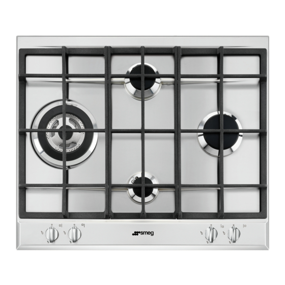
Smeg P64XGHUE
o
32
32
35
35
36
36
36
37
38
38
39
40
40
40
41
43
43
43
45
45
45
46
47
48
50
56
57
31
Advertisement
Table of Contents

Related Manuals for Smeg P64XGHUE


Summary of Contents for Smeg P64XGHUE
-
Page 1: Table Of Contents
These instructions apply only for the destination countries listed on the appliance's data plate. This is a class 3 built in hob. We advise you to read this manual carefully, which contains all the instructions for maintaining the appliance's aesthetic and functional qualities. For further information on the product: www.smeg.com... -
Page 2: Instructions
Instructions 1 Instructions • Cleaning and maintenance must not be carried out by unsupervised 1.1 General safety instructions children. • Make sure that the flame- Risk of personal injury spreader crowns are correctly • During use the appliance and its positioned in their housings with accessible parts become very hot. - Page 3 Instructions • Switch off the appliance • Cooking vessels or griddle plates immediately after use. should be placed inside the perimeter of the hob. • Do not modify this appliance. • All pans must have smooth, flat • Do not try to repair the appliance bottoms.
- Page 4 Instructions Installation • The hoses should not come into contact with moving parts and • This appliance must not be should not be crushed in any way. installed in a boat or caravan. • If required, use a pressure • The appliance must not be regulator that complies with installed on a pedestal.
-
Page 5: Manufacturer Liability
Instructions • The adjustment conditions for this 1.2 Manufacturer liability appliance are shown on the gas The manufacturer declines all liability setting label. for damage to persons or property • This appliance is not connected to caused by: an exhaust system for combustion •... -
Page 6: Identification Plate
Instructions 1.4 Identification plate • Consign the appliance to the appropriate selective collection The identification plate bears the centres for electrical and technical data, serial number and electronic equipment waste, or brand name of the appliance. Do not remove the identification plate for deliver it back to the retailer when any reason. -
Page 7: How To Read The User Manual
Instructions 1.7 How to read the user manual This user manual uses the following reading conventions: Instructions General information on this user manual, on safety and final disposal. Description Description of the appliance and its accessories. Information on the use of the appliance and its accessories, cooking advice. -
Page 8: Description
Description 2 Description 2.1 General Description 60 cm 72 cm... -
Page 9: Symbols
Description AUX = Auxiliary Burner knobs SR = Semi-rapid RR = Reduced rapid RR* = Reduced rapid R = Rapid UR = Ultra rapid UR2 int = internal crown ultra rapid UR2 est = external crown ultra rapid 2.2 Symbols Cooking zones Useful for lighting and adjusting the hob burners. -
Page 10: Use
3 Use Improper use 3.1 Instructions Risk of damage to surfaces Improper use • Do not use aluminium foil to cover the Danger of burns burners or hob body. • The cooking vessels or griddle plates • Make sure that the flame-spreader should be placed inside the perimeter of crowns are correctly positioned in their the hob. -
Page 11: Using The Hob
3.3 Using the hob Correct positioning of the grids Under the grids there are silicone rests with All the appliance's control and monitoring a hole that must be centred onto the devices are located together on the front matching fixing pins on the surface. panel. - Page 12 Practical tips for using the hob Limitations on griddle use For better burner efficiency and to minimise gas consumption, use pans with lids and of suitable size for the burner, so that flames do not reach up the sides of the pan. Once the contents come to the boil, turn down the flame far enough to ensure that the liquid does not boil over.
-
Page 13: Cleaning And Maintenance
Cleaning and maintenance 4 Cleaning and maintenance 4.2 Cleaning the appliance To keep the surfaces in good condition, 4.1 Instructions they should be cleaned regularly after use. Let them cool first. Improper use Risk of damage to surfaces Ordinary daily cleaning Always use only specific products that do •... - Page 14 Cleaning and maintenance Cooking hob grids Igniters and thermocouples Remove the grids and clean them with For correct operation the igniters and lukewarm water and non-abrasive thermocouples must always be perfectly detergent. Make sure to remove any clean. Check them frequently and clean encrustations.
-
Page 15: Installation
Installation 5 Installation 5.2 Section cut from the work surface The following operation requires 5.1 Safety instructions building and/or carpentry work Heat production during appliance and must therefore be carried out operation by a competent tradesman. Risk of fire Installation can be carried out on various materials such as masonry, •... -
Page 16: Mounting
Installation 5.3 Mounting Over empty kitchen unit or drawers If there are other pieces of furniture (lateral Over built-in oven walls, drawers, etc.), dishwashers or fridges The distance between the hob and the under the hob, a double-layer wooden kitchen furniture or other installed base must be installed at least 10 mm from appliances must be enough to ensure the bottom of the hob to avoid any... -
Page 17: Fixing Brackets
Installation Hob seal 5.4 Fixing brackets Screw the fixing brackets (A) into the holes To prevent leakage of liquid between the on the sides of the bottom casing to frame of the hob and the work surface, put properly fasten the hob to the structure. the insulating seal provided in position before assembly. -
Page 18: Gas Connection
Installation 5.5 Gas connection Carefully screw the connector 3 to the gas connector 1 of the appliance, placing the Gas leak seal 2 between them. Danger of explosion • After carrying out any operation, check that the tightening torque of gas connections is between 10 Nm and 15 Nm. - Page 19 Installation Connection to LPG Extraction of the combustion products Use a pressure regulator and make the This appliance is not connected to connection on the gas cylinder following an exhaust system for combustion the guidelines set out in the standards in products.
-
Page 20: Adaptation To Different Types Of Gas
Installation 5.6 Adaptation to different types of 1 Extraction using a hood 2 Extraction without a hood If other types of gas are to be used, the nozzles must be replaced and the primary A Single natural draught chimney air must be adjusted. In order to replace the B Single chimney with extractor fan nozzles and adjust the burners, the hob top C Directly outdoors with wall- or window-... - Page 21 Installation 5. The two rear screws need to be removed 3. Pull the knobs upwards to remove them. only on 70 cm models. 4. Remove the screws fastening the top and 6. Remove the top. the plates corresponding to each burner zone.
- Page 22 Installation Replacing nozzles Adjusting the minimum setting for natural or city gas Light the burner and turn it to the minimum position. Extract the gas tap knob and turn the adjustment screw next to the tap rod (depending on the model) until the correct minimum flame is achieved.
- Page 23 Installation Lubricating the gas taps Over time the gas taps may become difficult It is possible to identify the to turn and get blocked. Clean them available gas types based on the internally and replace the lubrication country the appliance is to be grease.
- Page 24 Installation Burner and nozzle characteristics tables Natural Gas G20 – 20 mbar UR2 int. UR2 ext. Rated heating capacity (kW) 1.10 1.70 2.60 2.60 3.10 3.50 1.00 3.20 Nozzle diameter (1/100 mm) Reduced flow rate (W) 1600 1400 Primary air (mm) Natural Gas G20 –...
- Page 25 Installation LPG G30/31 - 37 mbar UR2 int. UR2 ext. Rated heating capacity (kW) 1.10 1.70 2.60 2.60 3.10 3.50 1.00 3.20 Nozzle diameter (1/100 mm) Reduced flow rate (W) 1100 1600 1400 Primary air (mm) Rated flow rate G30 (g/h) Rated flow rate G31 (g/h) LPG G30/31 - 50 mbar UR2 int.
-
Page 26: Electrical Connection
Installation 5.7 Electrical connection The appliance can work in the following modes: Power voltage • 220-240 V 1N~ Danger of electrocution 220-240V~ 1 mm • Have the electrical connection performed by authorised technical personnel. 20 mm • Use personal protective equipment. Use a 3 x 1 mm²... -
Page 27: Instructions For The Installer
Installation 5.8 Instructions for the installer • The plug must be accessible after installation. Do not bend or trap the power cable. • The appliance must be installed according to the installation diagrams. • Do not try to unscrew or force the threaded elbow of the fitting.
Need help?
Do you have a question about the P64XGHUE and is the answer not in the manual?
Questions and answers