National Instruments PXI Express Series User Manual
Hide thumbs
Also See for PXI Express Series:
- User manual (83 pages) ,
- User manual (56 pages) ,
- Installation manual (11 pages)
Table of Contents
Advertisement
Quick Links
Download this manual
See also:
User Manual
Advertisement
Table of Contents

Related Manuals for National Instruments PXI Express Series


Summary of Contents for National Instruments PXI Express Series
- Page 1 Artisan Technology Group is your source for quality new and certified-used/pre-owned equipment SERVICE CENTER REPAIRS WE BUY USED EQUIPMENT • FAST SHIPPING AND DELIVERY Experienced engineers and technicians on staff Sell your excess, underutilized, and idle used equipment at our full-service, in-house repair center We also offer credit for buy-backs and trade-ins •...
- Page 2 PXI Express NI PXIe-1062Q User Manual NI PXIe-1062Q User Manual April 2012 371843D-01 Artisan Technology Group - Quality Instrumentation ... Guaranteed | (888) 88-SOURCE | www.artisantg.com...
- Page 3 11500 North Mopac Expressway Austin, Texas 78759-3504 USA Tel: 512 683 0100 For further support information, refer to the Technical Support and Professional Services appendix. To comment on National Instruments documentation, refer to the National Instruments Web site at and enter ni.com/info the Info Code feedback ©...
- Page 4 Instruments Corporation. National Instruments respects the intellectual property of others, and we ask our users to do the same. NI software is protected by copyright and other intellectual property laws. Where NI software may be used to reproduce software or other materials belonging to others, you may use NI software only to reproduce materials that you may reproduce in accordance with the terms of any applicable license or other legal restriction.
- Page 5 CUSTOMIZED AND DIFFERS FROM NATIONAL INSTRUMENTS' TESTING PLATFORMS AND BECAUSE A USER OR APPLICATION DESIGNER MAY USE NATIONAL INSTRUMENTS PRODUCTS IN COMBINATION WITH OTHER PRODUCTS IN A MANNER NOT EVALUATED OR CONTEMPLATED BY NATIONAL INSTRUMENTS, THE USER OR APPLICATION DESIGNER IS ULTIMATELY...
-
Page 6: Table Of Contents
Installing Slot Blockers ...................2-5 Rack Mounting ......................2-5 Connecting Safety Ground.....................2-6 Connecting to Power Source..................2-6 Installing a PXI Express System Controller ..............2-7 © National Instruments NI PXIe-1062Q User Manual Artisan Technology Group - Quality Instrumentation ... Guaranteed | (888) 88-SOURCE | www.artisantg.com... - Page 7 Contents Installing Peripheral Modules..................2-9 Power Inhibit Switch LED Indicator................2-10 Remote Voltage Monitoring and Control..............2-11 Inhibit Mode Switch ...................... 2-13 PXI_CLK10 Rear Connectors..................2-13 PXI Express System Configuration with MAX ............2-14 PXI-1 System Configuration................2-15 Using System Configuration and Initialization Files ............ 2-16 Chapter 3 Maintenance Service Interval......................
-
Page 8: About This Manual
This font is also used for the proper names of disk drives, paths, directories, programs, subprograms, subroutines, device names, functions, operations, variables, filenames, and extensions. © National Instruments NI PXIe-1062Q User Manual Artisan Technology Group - Quality Instrumentation ... Guaranteed | (888) 88-SOURCE | www.artisantg.com... -
Page 9: Related Documentation
About This Manual Related Documentation The following documents contain information that you might find helpful as you read this manual: • IEEE 1101.1-1991, IEEE Standard for Mechanical Core Specifications for Microcomputers Using IEC 603-2 Connectors • IEEE 1101.10, IEEE Standard for Additional Mechanical Specifications for Microcomputers Using IEEE 1101.1 Equipment Practice •... -
Page 10: Getting Started
Software media with PXI Platform Services 2.0 or higher ❑ Read Me First: Safety and Electromagnetic Compatibility ❑ Chassis number labels © National Instruments NI PXIe-1062Q User Manual Artisan Technology Group - Quality Instrumentation ... Guaranteed | (888) 88-SOURCE | www.artisantg.com... -
Page 11: Key Features
United Kingdom 230 V BS 1363/IEC83 If you are missing any of the items listed in Table 1-1, or if you have the incorrect AC power cable, contact National Instruments. Key Features The NI PXIe-1062Q chassis combines a high-performance 8-slot... - Page 12 • Replacement power supply shuttle • EMC filler panels • Slot blockers for improved cooling performance • Factory installation services © National Instruments NI PXIe-1062Q User Manual Artisan Technology Group - Quality Instrumentation ... Guaranteed | (888) 88-SOURCE | www.artisantg.com...
-
Page 13: Chassis Description
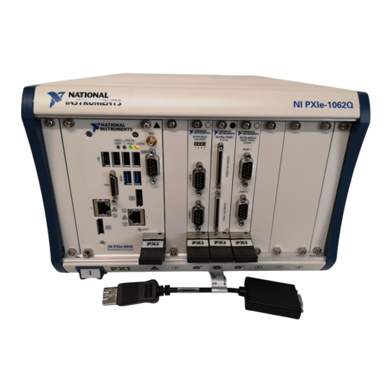
Chapter 1 Getting Started Chassis Description Figures 1-1 and 1-2 show the key features of the NI PXIe-1062Q chassis front and back panels. Figure 1-1 shows the front view of the NI PXIe-1062Q. Figure 1-2 shows the rear view of the NI PXIe-1062Q. NI PXIe-1062Q 1 Power Inhibit Switch 7 System Controller Expansion Slots... - Page 14 7 Remote Inhibit and Voltage Monitoring Connector 14 Power Supply Shuttle Mounting Screws (8x) Figure 1-2. Rear View of the NI PXIe-1062Q Chassis © National Instruments NI PXIe-1062Q User Manual Artisan Technology Group - Quality Instrumentation ... Guaranteed | (888) 88-SOURCE | www.artisantg.com...
-
Page 15: Optional Equipment
Chapter 1 Getting Started Optional Equipment Contact National Instruments to order the following options for the NI PXIe-1062Q chassis. EMC Filler Panels Optional EMC filler panel kits are available from National Instruments. Rack Mount Kit There are two optional kits for mounting the NI PXIe-1062Q chassis into a rack. -
Page 16: System Controller Slot
32-bit PXI functionality except for PXI Local Bus. The hybrid peripheral slot only connects to PXI Local Bus 6 left and right. © National Instruments NI PXIe-1062Q User Manual Artisan Technology Group - Quality Instrumentation ... Guaranteed | (888) 88-SOURCE | www.artisantg.com... -
Page 17: Pxi Peripheral Slots
Chapter 1 Getting Started PXI Peripheral Slots There are four PXI peripheral slots which will accept PXI or CompactPCI peripherals: slot 2, slot 6, slot 7, and slot 8. These slots are on the backplane’s 32-bit PCI bus. These slots offer full PXI functionality, but have no PXI Express features. -
Page 18: Pxi Local Bus
8 are not routed anywhere. Local bus signals may range from high-speed TTL signals to analog signals as high as 42 V. © National Instruments NI PXIe-1062Q User Manual Artisan Technology Group - Quality Instrumentation ... Guaranteed | (888) 88-SOURCE | www.artisantg.com... -
Page 19: Pxi Trigger Bus
Chapter 1 Getting Started Initialization software uses the configuration information specific to each adjacent peripheral module to evaluate local bus compatibility. Trigger Trigger Trigger Trigger Trigger Trigger Trigger PXI_LB6 PXI_LB6 PXI_LB6 PXI_LB6 PXI_LB6 PXI_LB PXI_LB (12:0) (12:0) Figure 1-4. PXI Trigger Bus and Local Bus Connectivity Diagram PXI Trigger Bus All slots share eight trigger lines.You can use these trigger lines in a variety of ways. - Page 20 10 MHz 10 MHz REF IN REF OUT PXI_CLK10 PXIe_CLK100 PXIe_SYNC100 PXI_CLK10_IN Figure 1-5. Distribution of PXI_CLK10, PXIe_CLK100, and PXIe_SYNC100 © National Instruments 1-11 NI PXIe-1062Q User Manual Artisan Technology Group - Quality Instrumentation ... Guaranteed | (888) 88-SOURCE | www.artisantg.com...
- Page 21 Chapter 1 Getting Started PXI_CLK10, PXIe_CLK100 and PXIe_SYNC100 have the default timing relationship described in Figure 1-6. 0 1 2 3 4 5 6 7 8 9 0 1 2 3 4 5 6 7 8 9 0 1 2 3 4 5 6 7 8 9 PXIe_CLK100 PXI_CLK10 PXIe_SYNC100...
-
Page 22: Pxie_Sync_Ctrl
Connector Pinout for the System Timing Slot, for system timing slot pinout. Refer to Appendix A, Specifications, for the PXIe_SYNC_CTRL input specifications. © National Instruments 1-13 NI PXIe-1062Q User Manual Artisan Technology Group - Quality Instrumentation ... Guaranteed | (888) 88-SOURCE | www.artisantg.com... - Page 23 Chapter 1 Getting Started By default, a high-level detected by the backplane on the PXIe_SYNC_CTRL pin causes a synchronous restart for the PXIe_SYNC100 signal. On the next PXI_CLK10 edge the PXIe_SYNC100 signal will restart. This will allow several chassis to have their PXIe_SYNC100 in phase with each other.
-
Page 24: Installation And Configuration
Under such conditions, this equipment is unsafe and may ignite the gases or gas fumes. © National Instruments NI PXIe-1062Q User Manual Artisan Technology Group - Quality Instrumentation ... Guaranteed | (888) 88-SOURCE | www.artisantg.com... -
Page 25: Chassis Cooling Considerations
Part Replacement—Only service this equipment with parts that are exact replacements, both electrically and mechanically. Contact National Instruments for replacement part information. Installation of parts with those that are not direct replacements may cause harm to personnel operating the chassis. Furthermore, damage or fire may occur if replacement parts are unsuitable. - Page 26 Chapter 2 Installation and Configuration 1.75 [44.45] 1.75 [44.45] NI PXIe-1062Q 3.00 [76.20] Figure 2-1. NI PXIe-1062Q Cooling Clearances © National Instruments NI PXIe-1062Q User Manual Artisan Technology Group - Quality Instrumentation ... Guaranteed | (888) 88-SOURCE | www.artisantg.com...
- Page 27 Chapter 2 Installation and Configuration 1 Primary Air Exhaust Vent 3 Primary Air Intake Vent 2 Air Filter 4 Secondary Air Intake/Exhaust Vents Figure 2-2. NI PXIe-1062Q Vents NI PXIe-1062Q User Manual ni.com Artisan Technology Group - Quality Instrumentation ... Guaranteed | (888) 88-SOURCE | www.artisantg.com...
-
Page 28: Chassis Ambient Temperature Definition
Rack Mounting Rack mount applications require the optional rack mount kits available from National Instruments. Refer to the instructions supplied with the rack mount kits to install your NI PXIe-1062Q chassis in an instrument rack. Refer to Figure A-3, NI Chassis Rack Mount Kit Components. -
Page 29: Connecting Safety Ground
Chapter 2 Installation and Configuration Connecting Safety Ground The NI PXIe-1062Q chassis are designed with a three-position NEMA 5-15 style Caution plug for the U.S. that connects the ground line to the chassis ground. To minimize shock hazard, make sure the electrical power outlet you use to power the chassis has an appropriate earth safety ground. -
Page 30: Installing A Pxi Express System Controller
2 NI PXIe-1062Q Chassis 4 System Controller Front Panel Mounting Screws (4x) Figure 2-3. Installing a PXI Express System Controller © National Instruments NI PXIe-1062Q User Manual Artisan Technology Group - Quality Instrumentation ... Guaranteed | (888) 88-SOURCE | www.artisantg.com... - Page 31 Chapter 2 Installation and Configuration When you begin to feel resistance, push up on the injector/ejector handle to seat the system controller fully into the chassis frame. Secure the system controller front panel to the chassis using the system controller front-panel mounting screws. Connect the keyboard, mouse, and monitor to the appropriate connectors.
-
Page 32: Installing Peripheral Modules
Secure the module front panel to the chassis using the module front-panel mounting screws. © National Instruments NI PXIe-1062Q User Manual Artisan Technology Group - Quality Instrumentation ... Guaranteed | (888) 88-SOURCE | www.artisantg.com... -
Page 33: Power Inhibit Switch Led Indicator
Chapter 2 Installation and Configuration 1 Peripheral Module Front Panel Mounting Screws (2x) 4 Injector/Ejector Rail 2 NI PXI Express System Controller 5 Injector/Ejector Handle 3 NI PXIe-1062Q Chassis 6 PXI Peripheral Module Figure 2-5. Installing PXI, PXI Express, or CompactPCI Peripheral Modules Power Inhibit Switch LED Indicator The chassis power inhibit switch has an integrated LED. -
Page 34: Remote Voltage Monitoring And Control
DB-9 Pin Signal Logic Ground +5 VDC Reserved +3.3 VDC Inhibit (Active Low) +12 VDC Reserved –12 VDC Logic Ground © National Instruments 2-11 NI PXIe-1062Q User Manual Artisan Technology Group - Quality Instrumentation ... Guaranteed | (888) 88-SOURCE | www.artisantg.com... - Page 35 Chapter 2 Installation and Configuration Caution When connecting digital voltmeter probes to the rear 9-pin D-SUB (DB-9) connector, be careful not to short the probe leads together. Doing so could damage the power supply. You can use a digital voltmeter to ensure all voltage levels in the NI PXIe-1062Q chassis are within the allowable limits.
-
Page 36: Inhibit Mode Switch
PXI_CLK10 to another chassis. Refer to the System Reference Clock section of Chapter 1, Getting Started, for details about these signals. © National Instruments 2-13 NI PXIe-1062Q User Manual Artisan Technology Group - Quality Instrumentation ... Guaranteed | (888) 88-SOURCE | www.artisantg.com... -
Page 37: Pxi Express System Configuration With Max
Chapter 2 Installation and Configuration PXI Express System Configuration with MAX The PXI Platform Services software included with your chassis automatically identifies your PXI Express system components to generate file. You can configure your entire PXI system and pxiesys.ini identify PXI-1 chassis through Measurement & Automation Explorer (MAX), included with your system controller. - Page 38 For detailed information pxisys.ini about initialization files, refer to the PXI specification at www.pxisa.org © National Instruments 2-15 NI PXIe-1062Q User Manual Artisan Technology Group - Quality Instrumentation ... Guaranteed | (888) 88-SOURCE | www.artisantg.com...
-
Page 39: Using System Configuration And Initialization Files
Chapter 2 Installation and Configuration Using System Configuration and Initialization Files The PXI Express specification allows many combinations of PXI Express chassis and system modules. To assist system integrators, the manufacturers of PXI Express chassis and system modules must document the capabilities of their products. -
Page 40: Maintenance
CompactPCI or PXI Express modules. Caution Always disconnect the AC power cable before cleaning or servicing the chassis. © National Instruments NI PXIe-1062Q User Manual Artisan Technology Group - Quality Instrumentation ... Guaranteed | (888) 88-SOURCE | www.artisantg.com... -
Page 41: Interior Cleaning
Chapter 3 Maintenance Interior Cleaning Use a dry, low-velocity stream of air to clean the interior of the chassis. Use a soft-bristle brush for cleaning around components. Exterior Cleaning Clean the exterior surfaces of the chassis with a dry lint-free cloth or a soft-bristle brush. -
Page 42: Replacing The Modular Power Supply
Chapter 2, Installation and Configuration. If the power switch LED is not a steady green, contact National Instruments. Verify that the NI PXIe-1062Q chassis can meet the power requirements of your CompactPCI or PXI Express modules. Overloading the chassis can cause the breaker to trip. Refer to Appendix A, Specifications. -
Page 43: Installation
Chapter 3 Maintenance attach the power supply shuttle to the chassis. Refer to Figure 1-2, Rear View of the NI PXIe-1062Q Chassis, for the screw locations. Using a Phillips screwdriver, remove the screws. Pull on the two rear handles of the power supply shuttle to remove it from the back of the chassis. -
Page 44: Appendix A Specifications
3.3 V..........<±0.2% 5 V........... <±0.1% ±12 V ..........<±0.1% Efficiency ..........70% typical The operating range is guaranteed by design. © National Instruments NI PXIe-1062Q User Manual Artisan Technology Group - Quality Instrumentation ... Guaranteed | (888) 88-SOURCE | www.artisantg.com... - Page 45 Appendix A Specifications Power disconnect ........The AC power cable provides main power disconnect. The front-panel power switch causes the internal chassis power supply to provide DC power to the CompactPCI/PXI Express backplane. You also can use the rear-panel D-SUB 9-pin connector and power mode switch to control the internal chassis power supply.
- Page 46 3.3 V and 5 V ........Clamped at 20 to 30% above nominal output voltage Power supply shuttle MTTR ....Replacement in under 5 minutes © National Instruments NI PXIe-1062Q User Manual Artisan Technology Group - Quality Instrumentation ... Guaranteed | (888) 88-SOURCE | www.artisantg.com...
- Page 47 Appendix A Specifications Chassis Cooling Module cooling system NI PXIe-1062Q .......Forced air circulation (positive pressurization) through two 110 cfm fans with High/Auto speed selector Slot airflow direction ......Bottom of module to top of module Module cooling intake ......Bottom rear of chassis Module cooling exhaust......Along both sides and top of chassis Power supply cooling system ....Forced air circulation through...
- Page 48 High fan..........62 dBA Sound Power Auto fan (up to ~30 °C ambient) ... 52.8 dBA High fan..........72 dBA © National Instruments NI PXIe-1062Q User Manual Artisan Technology Group - Quality Instrumentation ... Guaranteed | (888) 88-SOURCE | www.artisantg.com...
- Page 49 Appendix A Specifications Safety This product is designed to meet the requirements of the following standards of safety for information technology equipment: • IEC 61010-1, EN 61010-1 • UL 61010-1, CSA 61010-1 Note For UL and other safety certifications, refer to the product label or the Online Product Certification section.
- Page 50 Backplane bare-board material ....UL 94 V-0 Recognized Backplane connectors ......Conforms to IEC 917 and IEC 1076-4-101, and are UL 94 V-0 rated © National Instruments NI PXIe-1062Q User Manual Artisan Technology Group - Quality Instrumentation ... Guaranteed | (888) 88-SOURCE | www.artisantg.com...
- Page 51 Appendix A Specifications System Synchronization Clocks (PXI_CLK10, PXIe_CLK100, PXIe_SYNC100) 10 MHz System Reference Clock: PXI_CLK10 Maximum slot-to-slot skew ....250 ps Accuracy ..........±25 ppm max. (guaranteed over the operating temperature range) Maximum jitter ........5 ps RMS phase-jitter (10 Hz–1 MHz range) Duty-factor..........45%–55% Unloaded signal swing......3.3 V ±0.3 V For other specifications refer to the PXI-1 Hardware Specification.
- Page 52 ............3.0–5.5 V ............0–0.8 V PXI Star Trigger Maximum slot-to-slot skew ....250 ps Backplane characteristic impedance ..65 Ω ±10% © National Instruments NI PXIe-1062Q User Manual Artisan Technology Group - Quality Instrumentation ... Guaranteed | (888) 88-SOURCE | www.artisantg.com...
- Page 53 Appendix A Specifications Notes For PXI slot to PXI Star mapping refer to the System Timing Slot section of Chapter 1, Getting Started. For other specifications refer to the PXI-1 Hardware Specification. PXI Differential Star Triggers (PXIe-DSTARA, PXIe-DSTARB, PXIe-DSTARC) Maximum slot-to-slot skew ....150 ps Maximum differential skew....25 ps Backplane differential impedance ..100 Ω...
- Page 54 Notice that the front and rear chassis mounting holes (size M4) are symmetrical. © National Instruments A-11 NI PXIe-1062Q User Manual Artisan Technology Group - Quality Instrumentation ... Guaranteed | (888) 88-SOURCE | www.artisantg.com...
- Page 55 Appendix A Specifications Dimensions are in inches [millimeters] 10.68 [271.4] NI PXIe-1062Q 6.97 [177.1] 0.57 [14.5] 1.68 12.334 [313.28] [42.6] 1.40 [35.6] 1.823 [46.30] 3.542 Front of [89.97] PXI Card 1.844 [46.84] 2.13 0.30 [7.25] [54.2] 15.61 [396.5] Figure A-1. NI PXIe-1062Q Chassis Dimensions (Front and Side) NI PXIe-1062Q User Manual A-12 ni.com...
- Page 56 Appendix A Specifications 1.01 12.700 [322.58] [25.7] 1.02 [25.8] 8.650 [219.7] Figure A-2. NI PXIe-1062Q Chassis Dimensions (Bottom) © National Instruments A-13 NI PXIe-1062Q User Manual Artisan Technology Group - Quality Instrumentation ... Guaranteed | (888) 88-SOURCE | www.artisantg.com...
- Page 57 Appendix A Specifications Figure A-3 shows the chassis rack mount kit components. 1 Front Rack Mount Kit 2 NI Chassis 3 Optional Rear Rack Mount Kit Figure A-3. NI Chassis Rack Mount Kit Components Note The chassis shown in Figure A-3 is representative of the NI PXI-1042/NI PXIe-1062Q product line.
- Page 58 For more detailed information, refer to the PXI-5 PXI Express Hardware Specification, Revision 2.0. Contact the PXI Systems Alliance for a copy of the specification. © National Instruments NI PXIe-1062Q User Manual Artisan Technology Group - Quality Instrumentation ... Guaranteed | (888) 88-SOURCE | www.artisantg.com...
- Page 59 Appendix B Pinouts System Controller Slot Pinouts Table B-1. XP1 Connector Pinout for the System Controller Slot Pins Signals 3.3V Table B-2. XP2 Connector Pinout for the System Controller Slot 3PETp1 3PETn1 3PERp1 3PERn1 3PETp2 3PETn2 3PETp3 3PETn3 3PERp3 3PERn3 3PERp2 3PERn2 4PETp0...
- Page 60 Table B-4. XP4 Connector Pinout for the System Controller Slot 5Vaux SYSEN# WAKE# ALERT# PXI_TRIG3 PXI_TRIG4 PXI_TRIG5 PXI_TRIG6 PXI_TRIG2 PXI_STAR PXI_CLK10 PXI_TRIG1 PXI_TRIG0 PXI_TRIG7 PXI_LBR6 © National Instruments NI PXIe-1062Q User Manual Artisan Technology Group - Quality Instrumentation ... Guaranteed | (888) 88-SOURCE | www.artisantg.com...
- Page 61 Appendix B Pinouts System Timing Slot Pinouts Table B-5. TP2 Connector Pinout for the System Timing Slot PXIe_DSTARC0+ PXIe_DSTARC0– PXIe_DSTARC8+ PXIe_DSTARC8– GND PXIe_DSTARB8+ PXIe_DSTARB8– PXIe_DSTARA0+ PXIe_DSTARA0– PXIe_DSTARC9+ PXIe_DSTARC9– GND PXIe_DSTARA8+ PXIe_DSTARA8– PXIe_DSTARB0+ PXIe_DSTARB0– PXIe_DSTARA9+ PXIe_DSTARA9– PXI_STAR0 PXI_STAR1 PXIe_DSTARB9+ PXIe_DSTARB9– PXI_STAR2 PXI_STAR3 PXI_STAR4 PXI_STAR5...
- Page 62 WAKE# ALERT# 3.3V 3.3V 3.3V PXI_TRIG3 PXI_TRIG4 PXI_TRIG5 PXI_TRIG6 PXI_TRIG2 ATNLED PXI_CLK10_IN PXI_CLK10 PXI_TRIG1 PXI_TRIG0 ATNSW# PXI_TRIG7 PXIe_SYNC_CTRL PXI_LBL6 PXI_LBR6 © National Instruments NI PXIe-1062Q User Manual Artisan Technology Group - Quality Instrumentation ... Guaranteed | (888) 88-SOURCE | www.artisantg.com...
- Page 63 Appendix B Pinouts Peripheral Slot Pinouts Table B-8. P1 Connector Pinout for the Peripheral Slot REQ64# ENUM# 3.3V AD[1] V(I/O) AD[0] ACK64# 3.3V AD[4] AD[3] AD[2] AD[7] 3.3V AD[6] AD[5] 3.3V AD[9] AD[8] M66EN C/BE[0]# AD[12] V(I/O) AD[11] AD[10] 3.3V AD[15] AD[14] AD[13]...
- Page 64 PXI_LBR6 V(I/O) V(I/O) V(I/O) V(I/O) V(I/O) V(I/O) 64EN# PXI_LBR7 PXI_LBR8 PXI_LBR9 PXI_LBR10 PXI_LBR11 PXI_LBR12 PXI_LBL7 PXI_LBL8 PXI_LBL9 PXI_LBL10 PXI_LBL11 PXI_LBL12 © National Instruments NI PXIe-1062Q User Manual Artisan Technology Group - Quality Instrumentation ... Guaranteed | (888) 88-SOURCE | www.artisantg.com...
- Page 65 Appendix B Pinouts Hybrid Slot Pinouts Table B-10. P1 Connector Pinout for the Hybrid Slot REQ64# ENUM# 3.3V AD[1] V(I/O) AD[0] ACK64# 3.3V AD[4] AD[3] AD[2] AD[7] 3.3V AD[6] AD[5] 3.3V AD[9] AD[8] M66EN C/BE[0]# AD[12] V(I/O) AD[11] AD[10] 3.3V AD[15] AD[14] AD[13]...
- Page 66 SYSEN# WAKE# ALERT# 3.3V 3.3V 3.3V PXI_TRIG3 PXI_TRIG4 PXI_TRIG5 PXI_TRIG6 PXI_TRIG2 ATNLED PXI_STAR PXI_CLK10 PXI_TRIG1 PXI_TRIG0 ATNSW# PXI_TRIG7 PXI_LBL6 PXI_LBR6 © National Instruments NI PXIe-1062Q User Manual Artisan Technology Group - Quality Instrumentation ... Guaranteed | (888) 88-SOURCE | www.artisantg.com...
- Page 67 Technical Support and Professional Services Log in to your National Instruments User Profile to get ni.com personalized access to your services. Visit the following sections of for technical support and professional services: ni.com • Support—Technical support at includes the ni.com/support following resources: –...
- Page 68 Appendix C Technical Support and Professional Services • System Integration—If you have time constraints, limited in-house technical resources, or other project challenges, National Instruments Alliance Partner members can help. To learn more, call your local NI office or visit ni.com/alliance •...
- Page 69 Equal or less than. Percent. Amperes. Alternating current. ANSI American National Standards Institute. Auto Automatic fan speed control. American Wire Gauge. © National Instruments NI PXIe-1062Q User Manual Artisan Technology Group - Quality Instrumentation ... Guaranteed | (888) 88-SOURCE | www.artisantg.com...
- Page 70 Glossary backplane An assembly, typically a printed circuit board, with connectors and signal paths that bus the connector pins. Bayonet Neill Concelman connector; a commonly used coaxial connector. Celsius. Cubic feet per minute. Code of Federal Regulations. Centimeters. CompactPCI An adaptation of the Peripheral Component Interconnect (PCI) Specification 2.1 or later for industrial and/or embedded applications requiring a more robust mechanical form factor than desktop PCI.
- Page 71 International Electrotechnical Commission; an organization that sets international electrical and electronics standards. IEEE Institute of Electrical and Electronics Engineers. Mainframe peak current. © National Instruments NI PXIe-1062Q User Manual Artisan Technology Group - Quality Instrumentation ... Guaranteed | (888) 88-SOURCE | www.artisantg.com...
- Page 72 Glossary Inches. inhibit To turn off. jitter A measure of the small, rapid variations in clock transition times from their nominal regular intervals. Units: seconds RMS. Kilograms. Kilometers. Pounds. Light emitting diode. line regulation The maximum steady-state percentage that a DC voltage output will change as a result of a specified change in input AC voltage (step change from 90 to 132 VAC or 180 to 264 VAC).
- Page 73 Installing such a device into any other slot can damage the device, the PXI backplane, or both. © National Instruments NI PXIe-1062Q User Manual Artisan Technology Group - Quality Instrumentation ... Guaranteed | (888) 88-SOURCE | www.artisantg.com...
- Page 74 Glossary system reference A 10 MHz clock, also called PXI_CLK10, that is distributed to all clock peripheral slots in the chassis, as well as a BNC connector on the rear of chassis labeled 10 MHz REF OUT. The system reference clock can be used for synchronization of multiple modules in a measurement or control system.
- Page 75 3-1 external clock source specifications, A-9 clearances for chassis cooling, 2-2 figure, 2-3 CLK10 rear connectors, 2-13 © National Instruments NI PXIe-1062Q User Manual Artisan Technology Group - Quality Instrumentation ... Guaranteed | (888) 88-SOURCE | www.artisantg.com...
- Page 76 Index rack mounting, 2-5 remote voltage monitoring and inhibiting fan, setting speed, 2-5 interface, 2-11 filler panel installation, 2-5 setting fan speed, 2-5 site considerations, 2-2 slot blocker installation, 2-5 testing power up, 2-6 ground, connecting, 2-6 unpacking the NI PXIe-1062Q, 1-1 installing a PXI Express system controller (figure), 2-7 instrument drivers (NI resources), C-1...
- Page 77 Index National Instruments support and peripheral module installation, 2-9 services, C-1 figure, 2-10 NI PXIe-1062Q peripheral slot pinouts fan speed, setting, 2-5 P1 connector (table), B-6 front view (figure), 1-4 P2 connector (table), B-7 installation. See installation, pinouts, B-1 configuration, and operation...
- Page 78 Index external clock source, A-9 mechanical, A-10 rack mount kit dimensions (figure), A-14 PXI differential star triggers rack mounting, 2-5 (PXIe-DSTARA, PXIe-DSTARB, kit, 1-6 PXIe-DSTARC), A-10 related documentation, viii PXI star trigger, A-9 remote voltage monitoring and inhibiting PXIe_SYNC_CTRL, A-9 interface, 2-11 rack mount kit dimensions (figure), A-14 replacing the power supply, 3-3...
- Page 79 NI PXIe-1062Q chassis, 1-1 Web resources, C-1 voltage monitoring connector. See DB-9 connector voltages at voltage monitoring connector (DB-9) (table), 2-12 © National Instruments NI PXIe-1062Q User Manual Artisan Technology Group - Quality Instrumentation ... Guaranteed | (888) 88-SOURCE | www.artisantg.com...
- Page 80 Artisan Technology Group is your source for quality new and certified-used/pre-owned equipment SERVICE CENTER REPAIRS WE BUY USED EQUIPMENT • FAST SHIPPING AND DELIVERY Experienced engineers and technicians on staff Sell your excess, underutilized, and idle used equipment at our full-service, in-house repair center We also offer credit for buy-backs and trade-ins •...
Need help?
Do you have a question about the PXI Express Series and is the answer not in the manual?
Questions and answers