Table of Contents
Advertisement
Quick Links
Advertisement
Table of Contents

Related Manuals for National Instruments PXIe-1078


Summary of Contents for National Instruments PXIe-1078
- Page 1 PXI Express PXIe-1078 User Manual PXIe-1078 User Manual December 2019 373204D-01...
- Page 2 11500 North Mopac Expressway Austin, Texas 78759-3504 USA Tel: 512 683 0100 For further support information, refer to the NI Services appendix. To comment on NI documentation, refer to the NI website at and enter the Info Code ni.com/info feedback © 2012–2019 National Instruments. All rights reserved.
- Page 3 National Instruments Corporation. National Instruments respects the intellectual property of others, and we ask our users to do the same. NI software is protected by copyright and other intellectual property laws. Where NI software may be used to reproduce software or other materials belonging to others, you may use NI software only to reproduce materials that you may reproduce in accordance with the terms of any applicable license or other legal restriction.
- Page 4 ™ The ExpressCard word mark and logos are owned by PCMCIA and any use of such marks by National Instruments is under license. The mark LabWindows is used under a license from Microsoft Corporation. Windows is a registered trademark of Microsoft Corporation in the United States and other countries.
- Page 5 Operation of this hardware in a residential area is likely to cause harmful interference. Users are required to correct the interference at their own expense or cease operation of the hardware. Changes or modifications not expressly approved by National Instruments could void the user’s right to operate the hardware under the local regulatory rules.
-
Page 6: Table Of Contents
Optional Equipment......................1-5 EMC Filler Panels ....................1-5 Rack Mount Kit ......................1-5 Slot Blockers......................1-5 Handle/Feet Kit......................1-5 PXIe-1078 Chassis Backplane Overview................. 1-6 Interoperability with CompactPCI................1-6 System Controller Slot....................1-7 Hybrid Peripheral Slots .................... 1-7 PXI Express Peripheral Slots..................1-8 PXI Local Bus ...................... - Page 7 Contents Chapter 3 Maintenance Service Interval ......................... 3-1 Preparation ........................3-1 Cleaning ..........................3-2 Interior Cleaning ....................... 3-2 Exterior Cleaning ...................... 3-2 Appendix A Pinouts Appendix B NI Services Index viii | ni.com...
-
Page 8: About This Manual
About This Manual The PXIe-1078 User Manual describes the features of the PXIe-1078 chassis and contains information about configuring the chassis, installing the modules, and operating the chassis. For PXIe-1078 specifications, refer to the PXIe-1078 Specifications on Note ni.com Related Documentation... -
Page 9: Getting Started
Getting Started This chapter describes the key features of the PXIe-1078 chassis and lists the kit contents and optional equipment you can order from National Instruments. Unpacking Carefully inspect the shipping container and the chassis for damage. Check for visible damage to the metal work. -
Page 10: Key Features
If you are missing any of the items listed in Table 1-1, or if you have the incorrect AC power cable, contact National Instruments. Key Features The PXIe-1078 combines a 9-slot PXI Express backplane with a structural design optimized for maximum usability in a wide range of applications. The key features of the PXIe-1078 chassis include the following: •... -
Page 11: Chassis Description
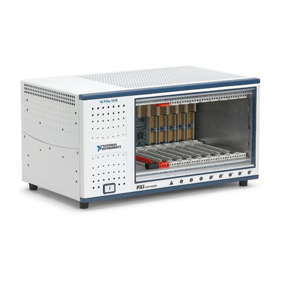
Chassis Description Figures 1-1 and 1-2 show the key features of the PXIe-1078 chassis front and back panels. Figure 1-1 shows the front view of the PXIe-1078. Figure 1-2 shows the rear view of the PXIe-1078. Figure 1-1. Front View of the PXIe-1078 Chassis... - Page 12 Chapter 1 Getting Started Figure 1-2. Rear View of the PXIe-1078 Chassis Rear Intake Vents Chassis Ground Screw AC Input AUTO/HIGH Fan Speed Selector Switch Power Supply Fan Exhaust Kensington Slot Removable Feet 1-4 | ni.com...
-
Page 13: Optional Equipment
Optional EMC filler panel kits are available from National Instruments through part number 778700-01. Rack Mount Kit A rack mount kit option is available for mounting the PXIe-1078 chassis into a 19 in. instrument cabinet. Refer to the PXIe-1078 Specifications on for more information. -
Page 14: Pxie-1078 Chassis Backplane Overview
PXIe-1078 Chassis Backplane Overview This section provides an overview of the backplane features for the PXIe-1078 chassis. Interoperability with CompactPCI The design of the PXIe-1078 provides you the flexibility to use the following devices in a single PXI Express chassis: •... -
Page 15: System Controller Slot
The hybrid peripheral slots provide PXI Express functionality (excluding DSTAR and PXI Star) and 32-bit PXI functionality except for PXI Local Bus. The hybrid peripheral slot only connects to PXI Local Bus 6 left and right. © National Instruments | 1-7... -
Page 16: Pxi Express Peripheral Slots
Chapter 1 Getting Started PXI Express Peripheral Slots There are three PXI Express peripheral slots: slots 2-4. PXI Express peripheral slots can accept the following modules: • A PXI Express peripheral with a x1 PCI Express link to the system slot •... -
Page 17: Pxi Trigger Bus
System Reference Clock The PXIe-1078 chassis supplies PXI_CLK10, PXIe_CLK100, and PXIe_SYNC100 to every peripheral slot with an independent driver for each signal. An independent buffer (having a source impedance matched to the backplane and a skew of less than 500 ps between slots) drives PXI_CLK10 to each peripheral slot. -
Page 18: Installation And Configuration
Installation and Configuration This chapter describes how to prepare and operate the PXIe-1078 chassis. Before connecting the chassis to a power source, read this chapter and the Read Me First: Safety and Electromagnetic Compatibility document included with your kit. Safety Information... -
Page 19: Chassis Cooling Considerations
Installation and Configuration Chassis Cooling Considerations The PXIe-1078 chassis is designed to operate on a bench or in an instrument rack. Regardless of the configuration, you must provide the cooling clearances as outlined in the following sections. Providing Adequate Clearance... - Page 20 PXIe-1078 User Manual Figure 2-2. PXIe-1078 Vents - P X I e - Power Supply Cooling Intake Vent Backplane Cooling Exhaust Vent Module Cooling Exhaust Vent Power Supply Cooling Exhaust Vent Module Cooling Intake Vent © National Instruments | 2-3...
- Page 21 Chapter 2 Installation and Configuration Figure 2-3. PXIe-1078 Cooling Clearances 1.75 in. (44.45 mm) NI-PXIe-1078 1.75 in. (44.45 mm) NATIONAL INSTRUMENTS 0.625 in. (15.89 mm) 1.75 in. On Desktop (44.45 mm) In Electronics Rack 1.75 in. (44.45 mm) 2-4 | ni.com...
-
Page 22: Chassis Ambient Temperature Definition
Setting Fan Speed The AUTO/HIGH fan-speed selector switch is on the rear panel of the PXIe-1078. Refer to Figure 1-2, Rear View of the PXIe-1078 Chassis, to locate the fan-speed selector switch. Select HIGH for maximum cooling performance (recommended) or AUTO for quieter operation. -
Page 23: Connecting Safety Ground
To completely remove power, you must disconnect the AC power cable. Attach input power through the rear AC inlet using the appropriate AC power cable supplied. Refer to Figure 1-2, Rear View of the PXIe-1078 Chassis, to locate the AC inlet. Installing a PXI Express System Controller This section contains general installation instructions for installing a PXI Express system controller in a PXIe-1078 chassis. - Page 24 Figure 2-4. Figure 2-4. Installing a PXI Express System Controller - P X I e - System Controller Front Panel Mounting Screws (4x) Injector/Ejector Handle NI PXI Express System Controller PXIe-1078 Chassis © National Instruments | 2-7...
- Page 25 Figure 2-5 shows a PXI Express system controller installed in the system controller slot of a PXIe-1078 chassis. You can place CompactPCI, CompactPCI Express, PXI, or PXI Express modules in other slots depending on the slot type.
-
Page 26: Installing Peripheral Modules
This section contains general installation instructions for installing a peripheral module in a PXIe-1078 chassis. Refer to your peripheral module user manual for specific instructions and warnings. To install a module, complete the following steps: Inspect the slot pins on the chassis backplane for any bending or damage prior to installation. - Page 27 Chapter 2 Installation and Configuration Figure 2-6. Installing PXI, PXI Express, or CompactPCI Peripheral Modules - P X I e - PXIe-1078 Chassis PXI Express Peripheral Module NI PXI Express System Controller Injector/Ejector Handle Peripheral Module Front Panel Mounting Screws (2x) Injector/Ejector Rail 2-10 | ni.com...
-
Page 28: Power Inhibit Switch Led Indicator
If the inhibit switch LED is red, the system fans have failed. Inhibit Mode Switch On the PXIe-1078 backplane is a four-position DIP switch (SW1). Switch 1 of SW1 controls the chassis inhibit mode. (Refer to Figure 2-7.) In its default position (OFF), the PXI Express controller controls the power supply on/off state based on the power switch on the chassis front panel. -
Page 29: Pxi Express System Configuration With Max
Chapter 2 Installation and Configuration PXI Express System Configuration with MAX The PXI Platform Services software included with your chassis automatically identifies your PXI Express system components to generate a file. You can configure your pxiesys.ini entire PXI system and identify PXI-1 chassis through Measurement & Automation Explorer (MAX), included with your system controller. -
Page 30: Using System Configuration And Initialization Files
.ini The capability documentation for the PXIe-1078 chassis is contained in the file chassis.ini on the software media that comes with the chassis. The information in this file is combined with information about the system controller to create a single system initialization file called (PXI System Initialization). -
Page 31: Service Interval
Maintenance This chapter describes basic maintenance procedures you can perform on the PXIe-1078 chassis. Disconnect the power cable prior to servicing a PXIe-1078 chassis. Caution Service Interval Clean dust from the chassis exterior (and interior) as needed, based on the operating environment. -
Page 32: Cleaning
Chapter 3 Maintenance Cleaning Cleaning procedures consist of exterior and interior cleaning of the chassis. Refer to your module user documentation for information about cleaning the individual CompactPCI or PXI Express modules. Always disconnect the AC power cable before cleaning or servicing the Caution chassis. -
Page 33: Appendix A Pinouts
Pinouts This appendix describes the connector pinouts for the NI PXIe-1078 chassis backplane. Table A-1 shows the XP1 connector pinout for the System Controller slot. Table A-2 shows the XP2 Connector Pinout for the System Controller slot. Table A-3 shows the XP3 Connector Pinout for the System Controller slot. - Page 34 Appendix A Pinouts System Controller Slot Pinouts Table A-1. XP1 Connector Pinout for the System Controller Slot Pins Signals 3.3 V 12 V 12 V Table A-2. XP2 Connector Pinout for the System Controller Slot 3PETp1 3PETn1 3PERp1 3PERn1 3PETp2 3PETn2 3PETp3 3PETn3...
- Page 35 2PERp2 2PERn2 2PETp3 2PETn3 3PETp0 3PETn0 3PERp0 3PERn0 2PERp3 2PERn3 Table A-4. XP4 Connector Pinout for the System Controller Slot 5Vaux SYSEN# WAKE# ALERT# PXI_TRIG3 PXI_TRIG4 PXI_TRIG5 PXI_TRIG6 PXI_TRIG2 PXI_STAR PXI_CLK10 PXI_TRIG1 PXI_TRIG0 PXI_TRIG7 PXI_LBR6 © National Instruments | A-3...
- Page 36 Appendix A Pinouts Hybrid Slot Pinouts Table A-5. P1 Connector Pinout for the Hybrid Slot REQ64# ENUM# 3.3 V AD[1] V(I/O) AD[0] ACK64# 3.3 V AD[4] AD[3] AD[2] AD[7] 3.3 V AD[6] AD[5] 3.3 V AD[9] AD[8] M66EN C/BE[0]# AD[12] V(I/O) AD[11] AD[10]...
- Page 37 Table A-7. XP4 Connector Pinout for the PXI Express/Hybrid Slot 5 Vaux SYSEN# WAKE# ALERT# 12 V 12 V 3.3 V 3.3 V 3.3 V PXI_TRIG3 PXI_TRIG4 PXI_TRIG5 PXI_TRIG6 PXI_TRIG2 ATNLED PXI_STAR PXI_CLK10 PXI_TRIG1 PXI_TRIG0 ATNSW# PXI_TRIG7 PXI_LBL6 PXI_LBR6 © National Instruments | A-5...
- Page 38 • System Integration—If you have time constraints, limited in-house technical resources, or other project challenges, National Instruments Alliance Partner members can help. To learn more, call your local NI office or visit ni.com/alliance © National Instruments | B-1...
- Page 39 Appendix B NI Services • Training and Certification—The NI training and certification program is the most effective way to increase application development proficiency and productivity. Visit for more information. ni.com/training – The Skills Guide assists you in identifying the proficiency requirements of your current application and gives you options for obtaining those skills consistent with your time and budget constraints and personal learning preferences.
- Page 40 See installation, configuration, PXI Express configuration in MAX, and operation 2-11 cooling PXI-1 configuration in MAX, 2-11 air cooling of PXIe-1078, 2-2 rack mounting, 2-5 filler panel installation, 2-5 setting fan speed, 2-5 setting fan speed, 2-5 site considerations, 2-1...
- Page 41 2-6 installation. See installation, trigger bus, 1-8 configuration, and operation key features, 1-2 maintenance. See maintenance of unpacking the PXIe-1078 chassis, 1-1 PXIe-1078 chassis optional equipment, 1-5 rack mounting, 2-5 safety ground, connecting, 2-5 unpacking, 1-1 PXIe-1078 backplane...
Need help?
Do you have a question about the PXIe-1078 and is the answer not in the manual?
Questions and answers