National Instruments PXIe-1065 User Manual
Hide thumbs
Also See for PXIe-1065:
- User manual (75 pages) ,
- User manual (8 pages) ,
- Installation manual (28 pages)

Related Manuals for National Instruments PXIe-1065


Summary of Contents for National Instruments PXIe-1065
- Page 1 PXI Express NI PXIe-1065 User Manual NI PXIe-1065 User Manual January 2017 371990D-01...
- Page 2 11500 North Mopac Expressway Austin, Texas 78759-3504 USA Tel: 512 683 0100 NI Services For further support information, refer to the appendix. To comment on NI documentation, refer to the NI website at and enter the Info Code ni.com/info feedback © 2007–2017 National Instruments. All rights reserved.
- Page 3 National Instruments Corporation. National Instruments respects the intellectual property of others, and we ask our users to do the same. NI software is protected by copyright and other intellectual property laws. Where NI software may be used to reproduce software or other materials belonging to others, you may use NI software only to reproduce materials that you may reproduce in accordance with the terms of any applicable license or other legal restriction.
- Page 4 ™ The ExpressCard word mark and logos are owned by PCMCIA and any use of such marks by National Instruments is under license. The mark LabWindows is used under a license from Microsoft Corporation. Windows is a registered trademark of Microsoft Corporation in the United States and other countries.
-
Page 5: Table Of Contents
Optional Equipment......................1-5 EMC Filler Panels ....................1-5 Rack Mount Kit ......................1-5 Slot Blockers......................1-5 NI PXIe-1065 Chassis Backplane Overview..............1-6 Interoperability with CompactPCI................1-6 System Controller Slot....................1-6 Hybrid Peripheral Slots .................... 1-7 PXI Peripheral Slots ....................1-7 PXI Express Peripheral Slots.................. - Page 6 Contents PXI_CLK10 Rear Connectors ..................2-11 PXI Express System Configuration with MAX..............2-11 PXI-1 System Configuration ..................2-12 Trigger Configuration in MAX................. 2-12 PXI Trigger Bus Routing..................2-13 Using System Configuration and Initialization Files............2-13 Chapter 3 Maintenance Service Interval ......................... 3-1 Preparation ........................3-1 Cleaning ..........................
-
Page 7: About This Manual
About This Manual The NI PXIe-1065 User Manual describes the features of the NI PXIe-1065 chassis and contains information about configuring the chassis, installing the modules, and operating the chassis. Related Documentation The following documents contain information that you might find helpful as you read this manual: IEEE 1101.1-1991, IEEE Standard for Mechanical Core Specifications for... -
Page 8: Getting Started
Getting Started This chapter describes the key features of the NI PXIe-1065 chassis and lists the kit contents and optional equipment you can order from National Instruments. Unpacking Carefully inspect the shipping container and the chassis for damage. Check for visible damage to the metal work. -
Page 9: Key Features
The chassis’ modular design ensures a high level of maintainability, resulting in a very low mean time to repair (MTTR). The NI PXIe-1065 chassis fully complies with the PXI-5 PXI Express Hardware Specification, offering advanced timing and synchronization features. - Page 10 NI PXIe-1065 User Manual High Reliability • 0 to 55 °C extended temperature range • Power supply, temperature, and fan monitoring • HALT tested for increased reliability • Field replaceable power supply shuttle Multi-Chassis Support • PXIe System Timing Slot for tight synchronization across chassis •...
-
Page 11: Chassis Description
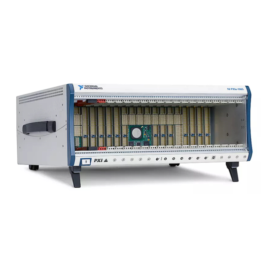
Chassis Description Figures 1-1 and 1-2 show the key features of the NI PXIe-1065 chassis front and back panels. Figure 1-1 shows the front view of the NI PXIe-1065. Figure 1-2 shows the rear view of the NI PXIe-1065. Figure 1-1. Front View of the NI PXIe-1065 Chassis... -
Page 12: Optional Equipment
Rack Mount Kit There are two optional kits for mounting the PXIe-1065 chassis into a rack. The first option is a pair of mounting brackets for use on the front of the chassis. The second option is a rear rack mount kit. -
Page 13: Ni Pxie-1065 Chassis Backplane Overview
NI PXIe-1065 Chassis Backplane Overview This section provides an overview of the backplane features for the NI PXIe-1065 chassis. Interoperability with CompactPCI The design of the NI PXIe-1065 provides you the flexibility to use the following devices in a single PXI Express chassis: •... -
Page 14: Hybrid Peripheral Slots
NI PXIe-1065 User Manual Hybrid Peripheral Slots The chassis provides four hybrid peripheral slots as defined by the PXI-5 PXI Express Hardware Specification: slot 7 and slots 11 to 13. A hybrid peripheral slot can accept the following peripheral modules: •... - Page 15 Chapter 1 Getting Started The system timing slot has 3 dedicated differential pairs (PXIe_DSTAR) connected from the TP1 and TP2 connectors to the XP3 connector for each PXI Express peripheral or hybrid peripheral slot, as well as routed back to the XP3 connector of the system timing slot as shown in Figure 1-3.
-
Page 16: Pxi Local Bus
NI PXIe-1065 User Manual PXI Local Bus The PXI backplane local bus is a daisy-chained bus that connects each peripheral slot with adjacent peripheral slots to the left and right, as shown in Figure 1-4. The backplane routes the full 13-line PXI Local Bus between adjacent PXI slots (slots 2 to 6 and 15 to 18) and PXI Local Bus 6 between all other slots. -
Page 17: Pxi Trigger Bus
System Reference Clock The PXIe-1065 chassis supplies the PXI 10 MHz system clock signal (PXI_CLK10) independently driven to each peripheral slot and PXIe_CLK100 and PXIe_SYNC100 to the PXI Express slots, hybrid slots, and system timing slot. - Page 18 NI PXIe-1065 User Manual Figure 1-5. Distribution of PXI_CLK10, PXIe_CLK100, and PXIe_SYNC100 10 MHz 10 MHz REF IN REF OUT PXI_CLK10_IN PXI_CLK10 PXI_CLK10, PXIe_CLK100 and PXIe_SYNC100 have the default timing relationship described in Figure 1-6. Figure 1-6. System Reference Clock Default Behavior...
- Page 19 Chapter 1 Getting Started You also can drive a 10MHz clock on the 10 MHz REF IN connector on the rear of the chassis. When a 10MHz clock is detected on this connector, the backplane automatically phase-locks the PXI_CLK10, PXIe_CLK100, and PXIe_SYNC100 signals to this external clock and distributes these signals to the slots (refer to Figure 1-5 for the distribution of PXI_CLK10, PXIe_CLK100 and PXIe_SYNC100).
- Page 20 NI PXIe-1065 User Manual PXIe_SYNC_CTRL PXIe_SYNC100 is by default a 10 ns pulse synchronous to PXI_CLK10. The frequency of PXIe_SYNC100 is 10/n MHz, where n is a positive integer. The default for n is 1, giving PXIe_SYNC100 a 100 ns period. However, the backplane allows n to be programmed to other integers.
-
Page 21: Installation And Configuration
Installation and Configuration This chapter describes how to prepare and operate the NI PXIe-1065 chassis. Before connecting the chassis to a power source, read this chapter and the Read Me First: Safety and Electromagnetic Compatibility document included with your kit. -
Page 22: Chassis Cooling Considerations
Providing Adequate Clearance The primary cooling exhaust vent for the NI PXIe-1065 is on the top of the chassis. The primary intake vent is on the rear of the chassis. The secondary intake and exhaust vents are located along the sides of the chassis. -
Page 23: Chassis Ambient Temperature Definition
NI PXIe-1065 User Manual Figure 2-2. NI PXIe-1065 Vents Primary Air Exhaust Vent Secondary Air Intake/Exhaust Vents (both sides) Primary Air Intake Vent Chassis Ambient Temperature Definition The chassis fan control system uses intake air temperature as the input for controlling fan speeds when in Auto Fan Speed mode. -
Page 24: Setting Fan Speed
Chapter 2 Installation and Configuration Setting Fan Speed The fan-speed selector switch is on the rear panel of the NI PXIe-1065 chassis. Refer to Rear View of the NI PXIe-1065 Chassis, to locate the fan-speed selector switch. Figure 1-2, Select High for maximum cooling performance or Auto for improved acoustic performance. -
Page 25: Connecting To Power Source
This section contains general installation instructions for installing a PXI Express system controller in a NI PXIe-1065 chassis. Refer to your PXI Express system controller user manual for specific instructions and warnings. To install a system controller, complete the following... - Page 26 Figure 2-3. Installing a PXIe System Controller NI PXI Express System Controller Injector/Ejector Handle NI PXIe-1065 Chassis System Controller Front Panel Mounting Screws (4x) When you begin to feel resistance, pull up on the injector/ejector handle to seat the system controller fully into the chassis frame.
-
Page 27: Installing Peripheral Modules
Chapter 1, This section contains general installation instructions for installing a peripheral module in a NI PXIe-1065 chassis. Refer to your peripheral module user manual for specific instructions and warnings. To install a module, complete the following steps: Connect the AC power source to the PXI Express chassis before installing the module. The AC power cord grounds the chassis and protects it from electrical damage while you install the module. -
Page 28: Power Inhibit Switch Led Indicator
Peripheral Module Front Panel Mounting Screws (2x) Injector/Ejector Rail NI PXI Express System Controller Injector/Ejector Handle NI PXIe-1065 Chassis PXI Peripheral Module Power Inhibit Switch LED Indicator The chassis power inhibit switch has an integrated LED. This LED indicates one of four different conditions: •... -
Page 29: Remote Voltage Monitoring And Control
Remote Voltage Monitoring and Control The NI PXIe-1065 chassis supports remote voltage monitoring and inhibiting through a female 9-pin D-SUB (DB-9) connector located on the rear panel. Table 2-1 shows the pinout of the 9-pin D-SUB (DB-9) connector. -
Page 30: Inhibit Mode Switch
Chapter 2 Installation and Configuration You can use a digital voltmeter to ensure all voltage levels in the NI PXIe-1065 chassis are within the allowable limits. Referring to Table 2-2, connect one lead of the voltmeter to a supply pin on the remote voltage monitoring connector (9-pin D-SUB) on the rear panel. Refer to Table 2-1 for a pinout diagram of the remote voltage monitoring connector. -
Page 31: Pxi_Clk10 Rear Connectors
NI PXIe-1065 User Manual PXI_CLK10 Rear Connectors There are two BNC connectors on the rear of the NI PXIe-1065 chassis for PXI_CLK10. The connectors are labeled IN and OUT. You can use them for supplying the backplane with System PXI_CLK10 or routing the backplane’s PXI_CLK10 to another chassis. Refer to the... -
Page 32: Pxi-1 System Configuration
Dynamic reservation/routing/deallocation is on the fly within a user program based upon National Instruments APIs such as NI-DAQmx. Static reservation of trigger lines can be implemented by the user in MAX through the Triggers tab. -
Page 33: Pxi Trigger Bus Routing
Click the Apply button. PXI Trigger Bus Routing Some National Instruments chassis, such as the PXI-1065 and the PXI-1044/1045, have the capability to route triggers from one bus to others within the same chassis using the Trigger Routing tab in MAX, as shown in Figure 2-6. - Page 34 Chapter 2 Installation and Configuration Device drivers and other utility software read the file to obtain system pxisys.ini information. The device drivers should have no need to directly read the file. For chassis.ini detailed information regarding initialization files, refer to the PXI Express specification at www.pxisa.org 2-14 | ni.com...
-
Page 35: Maintenance
Maintenance This chapter describes basic maintenance procedures you can perform on the NI PXIe-1065 chassis. Disconnect the power cable prior to servicing a NI PXIe-1065 chassis. Caution Service Interval Clean dust from the chassis exterior (and interior) as needed, based on the operating environment. -
Page 36: Exterior Cleaning
Resetting the AC Mains Circuit Breaker If the NI PXIe-1065 chassis is connected to an AC source and encounters an over-current condition, the circuit breaker on the rear panel will trip to prevent damage to the chassis. -
Page 37: Replacing The Modular Power Supply
First: Safety and Electromagnetic Compatibility document included with the kit. Removal The NI PXIe-1065 AC power supply is a replacement part for the NI PXIe-1065 AC chassis. Before attempting to replace the power supply shuttle, verify that there is adequate clearance behind the chassis. -
Page 38: Appendix A Specifications
Specifications This appendix contains specifications for the NI PXIe-1065 chassis. Specifications are subject to change without notice. Caution Electrical AC Input Input voltage range 100 to 240 VAC Operating voltage range 90 to 264 VAC Input frequency 50 Hz to 60 Hz... - Page 39 Appendix A Specifications DC Output DC current capacity (I Voltage Maximum Current +3.3 V 60 A +5 V 50 A +12 V 45 A -12 V 2.0 A Maximum combined +3.3 V, +5 V, and +12 V power is 699 W. Note Maximum total usable power is 701.5 W.
- Page 40 NI PXIe-1065 User Manual Total system slot current should not exceed 45 A. Note PCI V(I/O) pins in PXI-1 peripheral slots and hybrid peripheral slots are connected to +5 V. The maximum power dissipated in the system slot should not exceed 140 W.
- Page 41 Appendix A Specifications Chassis Cooling Module cooling system NI PXIe-1065 Forced air circulation (positive pressurization) through three 165 cfm fans with High/Auto speed selector Slot airflow direction Bottom of module to top of module Module cooling intake Bottom rear of chassis...
- Page 42 NI PXIe-1065 User Manual Storage Environment Ambient temperature range -40 to 71 °C (Tested in accordance with IEC 60068-2-1 and IEC 60068-2-2. Meets MIL-PRF-28800F Class 3 limits.) Relative humidity range 5 to 95%, noncondensing (Tested in accordance with IEC 60068-2-56.)
- Page 43 At the end of the product life cycle, all products must be sent to EU Customers a WEEE recycling center. For more information about WEEE recycling centers, National Instruments WEEE initiatives, and compliance with WEEE Directive 2002/96/EC on Waste and Electronic Equipment, visit ni.com/environment/ weee A-6 | ni.com...
- Page 44 NI PXIe-1065 User Manual National Instruments (RoHS) National Instruments RoHS ni.com/ (For information about China RoHS compliance, environment/rohs_china go to ni.com/environment/rohs_china Backplane Size 3U-sized; one system slot (with three system expansion slots) and 17 peripheral slots. Compliant with IEEE 1101.10 mechanical packaging.
- Page 45 Appendix A Specifications 100 MHz System Reference Clock: PXIe_CLK100 and PXIe_SYNC100 Maximum slot-to-slot skew 100 ps Accuracy ±25 ppm max. (guaranteed over the operating temperature range) Maximum jitter 3 ps RMS phase-jitter (10 Hz to 12 kHz range) 2 ps RMS phase-jitter (12 kHz to 20 MHz range) Duty-factor for PXIe_CLK100 45% to 55% Absolute single-ended voltage swing...
- Page 46 System Timing Slot For PXIe slot to PXI_DSTAR mapping refer to the Note Getting Started. section of Chapter 1, For other specifications, the NI PXIe-1065 complies with the PXI-5 PXI Express Hardware Specification. Mechanical Overall dimensions Standard chassis Height 6.97 in. (177.1 mm) Width 18.30 in.
- Page 47 Appendix A Specifications 0.57 in. (14.5 mm) is added to height when feet are installed. When tilted with Note front feet extended on table top, height is increased approximately 2.08 in. (52.8 mm) in front and 0.583 in. (14.8 mm) in rear. Weight 12.8 kg (28.2 lb) Chassis materials...
- Page 48 NI PXIe-1065 User Manual Figures A-1 and A-2 show the NI PXIe-1065 chassis dimensions. The holes shown are for the installation of the optional rack mount kits. You can install those kits on the front or rear of the chassis, depending on which end of the chassis you want to face toward the front of the instrument cabinet.
- Page 49 Appendix A Specifications Figure A-2. NI PXIe-1065 Chassis Dimensions (Bottom) Dimensions are in inches (millimeters) 12.700 (322.58) 2.524 (64.11) 15.504 (393.8) 1.017 (25.83) A-12 | ni.com...
- Page 50 Figure A-3. NI Chassis Rack Mount Kit Components Front Rack Mount Kit NI Chassis Optional Rear Rack Mount Kit The chassis shown in Figure A-3 is representative of the NI PXI-1044/1045 Note and NI PXIe-1065 product line. © National Instruments | A-13...
-
Page 51: Appendix B Pinouts
Pinouts This appendix describes the connector pinouts for the NI PXIe-1065 chassis backplane. Table B-1 shows the XP1 connector pinout for the System Controller slot. Table B-2 shows the XP2 Connector Pinout for the System Controller slot. Table B-3 shows the XP3 Connector Pinout for the System Controller slot. - Page 52 Appendix B Pinouts System Controller Slot Pinouts Table B-1. XP1 Connector Pinout for the System Controller Slot Pins Signals 3.3V B-2 | ni.com...
- Page 53 NI PXIe-1065 User Manual © National Instruments | B-3...
- Page 54 Appendix B Pinouts B-4 | ni.com...
- Page 55 NI PXIe-1065 User Manual © National Instruments | B-5...
- Page 56 Appendix B Pinouts B-6 | ni.com...
- Page 57 NI PXIe-1065 User Manual © National Instruments | B-7...
- Page 58 Appendix B Pinouts B-8 | ni.com...
- Page 59 NI PXIe-1065 User Manual © National Instruments | B-9...
- Page 60 Appendix B Pinouts B-10 | ni.com...
- Page 61 NI PXIe-1065 User Manual © National Instruments | B-11...
- Page 62 Appendix B Pinouts B-12 | ni.com...
- Page 63 NI PXIe-1065 User Manual © National Instruments | B-13...
- Page 64 Appendix B Pinouts B-14 | ni.com...
- Page 65 System Integration—If you have time constraints, limited in-house technical resources, or • other project challenges, National Instruments Alliance Partner members can help. To learn more, call your local NI office or visit ni.com/alliance © National Instruments | C-1...
- Page 66 Appendix C NI Services Training and Certification—The NI training and certification program is the most • effective way to increase application development proficiency and productivity. Visit for more information. ni.com/training – The Skills Guide assists you in identifying the proficiency requirements of your current application and gives you options for obtaining those skills consistent with your time and budget constraints and personal learning preferences.
- Page 67 Symbols ° Degrees. ≥ Equal or greater than. ≤ Equal or less than. Percent. Amperes. Alternating current. ANSI American National Standards Institute. Auto Automatic fan speed control. American Wire Gauge. © National Instruments | G-1...
- Page 68 Glossary backplane An assembly, typically a printed circuit board, with connectors and signal paths that bus the connector pins. Bayonet Neill Concelman connector; a commonly used coaxial connector. Celsius. Cubic feet per minute. Code of Federal Regulations. Centimeters. CompactPCI An adaptation of the Peripheral Component Interconnect (PCI) Specification 2.1 or later for industrial and/or embedded applications requiring a more robust mechanical form factor than desktop PCI.
- Page 69 NI PXIe-1065 User Manual efficiency Ratio of output power to input power, expressed as a percentage. Electronic Industries Association. Electromagnetic Compatibility. Electromagnetic Interference. Federal Communications Commission. filler panel A blank module front panel used to fill empty slots in the chassis.
- Page 70 Glossary Inches. inhibit To turn off. jitter A measure of the small, rapid variations in clock transition times from their nominal regular intervals. Units: seconds RMS. Kilograms. Kilometers. Pounds. Light emitting diode. line regulation The maximum steady-state percentage that a DC voltage output will change as a result of a specified change in input AC voltage (step change from 90 to 132 VAC or 180 to 264 VAC).
- Page 71 NI PXIe-1065 User Manual MTBF Mean time between failure. MTTR Mean time to repair. NEMA National Electrical Manufacturers Association. National Instruments. power supply shuttle A removable module that contains the chassis power supply. PCI eXtensions for Instrumentation. PXI_CLK10 10 MHz PXI system reference clock.
- Page 72 Glossary system reference A 10 MHz clock, also called PXI_CLK10, that is distributed to clock all peripheral slots in the chassis, as well as a BNC connector on the rear of chassis labeled 10 MHz REF OUT. The system reference clock can be used for synchronization of multiple modules in a measurement or control system.
- Page 73 Index cooling air cooling of PXIe-1065 chassis, 2-2 AC power cables (table), 1-2 filler panel installation, 2-4 setting fan speed, 2-4 slot blocker installation, 2-4 backplane hybrid peripheral slots, 1-6 interoperability with CompactPCI, 1-6 DB-9 connector overview, 1-5 pinout (table), 2-9...
- Page 74 MAX, 2-11 optional equipment, 1-5 PXI Express system controller installed rack mounting, 2-4 in a NI PXIe-1065 chassis rear view of NI PXIe-1065 chassis, 1-5 (figure), 2-7 safety ground, connecting, 2-4 PXI-1 configuration in MAX, 2-12 unpacking, 1-1 rack mounting, 2-4...
- Page 75 PXI Express peripheral slots, description, 1-7 100 MHz system reference clock PXI Express system controller, 2-5 (PXIe_CLK100 and figure, 2-6 PXIe_SYNC100), A-8 installing in a NI PXIe-1065 chassis CE compliance, A-6 (figure), 2-7 chassis cooling, A-4 PXI local bus, routing, 1-9 dimensions (figure), A-11, A-12...
- Page 76 TP2 connector (table), B-6 XP3 connector (table), B-7 XP4 connector (table), B-7 testing power up, 2-5 trigger bus, 1-9 unpacking the NI PXIe-1065 chassis, 1-1 voltage monitoring connector. See DB-9 connector voltages at voltage monitoring connector (DB-9) (table), 2-10 I-4 | ni.com...
Need help?
Do you have a question about the PXIe-1065 and is the answer not in the manual?
Questions and answers