Table of Contents
Advertisement
Quick Links
INSTALLATION GUIDE
8-Slot NI PXIe-1062Q Backplane
Contents
This guide describes installation requirements for the 8-slot
NI PXIe-1062Q backplane.
NI PXIe-1062Q Chassis Backplane Overview ....................................... 2
Interoperability with CompactPCI................................................... 2
System Controller Slot..................................................................... 3
Hybrid Peripheral Slots.................................................................... 3
PXI Peripheral Slots......................................................................... 3
System Timing Slot ......................................................................... 4
PXI Local Bus.................................................................................. 5
PXI Trigger Bus............................................................................... 6
System Reference Clock .................................................................. 6
PXIe_SYNC_CTRL ........................................................................ 9
Mechanical Requirements....................................................................... 9
Mounting.......................................................................................... 9
Cooling............................................................................................. 10
Handling.................................................................................................. 10
Dimensions ...................................................................................... 11
Electrical Requirements .......................................................................... 12
PXI Connectors................................................................................ 12
Power ............................................................................................... 12
Connector J29 ........................................................................... 12
Connector J27 ........................................................................... 15
Connector J26 ........................................................................... 15
Connector W1........................................................................... 16
Backplane Specifications ................................................................. 16
10 MHz System Reference Clock (PXI_CLK10) .................... 16
Pinouts..................................................................................................... 17
System Controller Slot Pinouts........................................................ 18
System Timing Slot Pinouts ............................................................ 19
Peripheral Slot Pinouts..................................................................... 21
Hybrid Slot Pinouts.......................................................................... 23
Advertisement
Table of Contents

Related Manuals for National Instruments PXIe-1062Q


Summary of Contents for National Instruments PXIe-1062Q
-
Page 1: Table Of Contents
INSTALLATION GUIDE 8-Slot NI PXIe-1062Q Backplane This guide describes installation requirements for the 8-slot NI PXIe-1062Q backplane. Contents NI PXIe-1062Q Chassis Backplane Overview ........2 Interoperability with CompactPCI........... 2 System Controller Slot..............3 Hybrid Peripheral Slots..............3 PXI Peripheral Slots................. 3 System Timing Slot ................. -
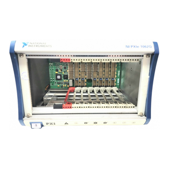
Page 2: Ni Pxie-1062Q Chassis Backplane Overview
This section provides an overview of the backplane features for the NI PXIe-1062Q chassis. Figure 1 shows the backplane. Figure 1. 8-Slot NI PXIe-1062Q Backplane Interoperability with CompactPCI With the NI PXIe-1062Q, you can use the following devices in a single PXI Express chassis: • PXI Express-compatible products •... -
Page 3: System Controller Slot
6, slot 7, and slot 8. These slots are on the backplane 32-bit PCI bus. These slots offer full PXI functionality, but have no PXI Express features. The 64-bit PCI signals on the P2 connectors are not connected. © National Instruments Corporation 8-Slot NI PXIe-1062Q Backplane Installation Guide... -
Page 4: System Timing Slot
The system timing slot has a pin (PXIe_SYNC_CTRL) through which a system timing module can control the PXIe_SYNC100 timing. Refer to the PXI Express Specification and the PXIe_SYNC_CTRL section for details. 8-Slot NI PXIe-1062Q Backplane Installation Guide ni.com... -
Page 5: Pxi Local Bus
Local bus signals may range from high-speed TTL signals to analog signals as high as 42 V. Initialization software uses the configuration information specific to each adjacent peripheral module to evaluate local bus compatibility. © National Instruments Corporation 8-Slot NI PXIe-1062Q Backplane Installation Guide... -
Page 6: Pxi Trigger Bus
System Reference Clock The NI PXIe-1062Q chassis supplies the PXI 10 MHz system clock signal (PXI_CLK10) independently driven to each peripheral slot, and PXIe_CLK100 and PXIe_SYNC100 to the hybrid slots and system timing slot. - Page 7 0 1 2 3 4 5 6 7 8 9 0 1 2 3 4 5 6 7 8 9 0 1 2 3 4 5 6 7 8 9 PXIe_CLK100 PXI_CLK10 PXIe_SYNC100 Figure 5. System Reference Clock Default Behavior © National Instruments Corporation 8-Slot NI PXIe-1062Q Backplane Installation Guide...
- Page 8 A copy of the backplane PXI_CLK10 is exported to the 10 MHz REF OUT pin of connector J27. An independent buffer drives this clock. Refer to Backplane Specifications for the specification information for the 10 MHz REF OUT signal on connector J27. 8-Slot NI PXIe-1062Q Backplane Installation Guide ni.com...
-
Page 9: Pxie_Sync_Ctrl
If you do not want to connect the backplane ground to the chassis, use insulated washers at these mounting holes. Refer to Figure 9 for the mounting hole positions. © National Instruments Corporation 8-Slot NI PXIe-1062Q Backplane Installation Guide... -
Page 10: Cooling
Cooling Note National Instruments is not responsible for damage to the backplane if inadequate cooling is used. You should mount a fan below the backplane. Airflow should be from the bottom to the top of the PXI modules. You must determine the airflow requirements for your system based on the PXI Hardware Specification. -
Page 11: Dimensions
0.100 in. (2.54 mm) 0.988 in. (25.1 mm) 5.933 in. (150.7 mm) 0.122 in. (3.1mm) 0.224 in. 0.800 in. (5.68 mm) (20.32 mm) 9.843 in. (250.0 mm) Figure 7. Dimensions © National Instruments Corporation 8-Slot NI PXIe-1062Q Backplane Installation Guide... -
Page 12: Electrical Requirements
Connector J29 Connector J29 is the NI PXIe-1062Q backplane power supply connector. Figure 9 shows the J29 location. Refer to Table 2 for the pin descriptions. Connector J29 consists of eight larger #12 pins (1–4 and 26–29) for power and 21 #20 pins (5–25) used mainly for signaling. - Page 13 CompactPCI Express specification defines. (The specification also defines uses and addressing. Improper use of the SMBus could result in system controller malfunctions. There are two SMBus slave devices on the NI PXIe-1062Q backplane. The Backplane Descriptor EEPROM is at slave address A4...
- Page 14 +12 V sense only, no power +3.3V_SENSE +3.3 V sense only, no power Ground plane +5V_SENSE +5 V sense only, no power +12V +12 V power plane Ground plane +5 V power plane Ground plane 8-Slot NI PXIe-1062Q Backplane Installation Guide ni.com...
-
Page 15: Connector J27
Figure 8 shows the J26 connector location. Refer to Table 3 for the pin descriptions. Table 3. Connector J26 Pin Descriptions Connector Signal Description PWRBTN# Input to system slot J12—pin F2 Ground plane LED1 J29—pin 14 LED2 J29—pin 15 © National Instruments Corporation 8-Slot NI PXIe-1062Q Backplane Installation Guide... -
Page 16: Connector W1
Maximum jitter........5 ps RMS in 10 Hz to 1 MHz range External clock sources Connectors........Connector J27 on rear of backplane or slot 2 J2 (pin D17) Input frequency........10 MHz ±100 ppm or better 8-Slot NI PXIe-1062Q Backplane Installation Guide ni.com... -
Page 17: Pinouts
Output impedance ......50 Ω ± 5 Ω Pinouts This section describes the connector pinouts for the NI PXIe-1062Q chassis backplane. Table 4 shows the XP1 connector pinout for the system controller slot. Table 5 shows the XP2 connector pinout for the system controller slot. -
Page 18: System Controller Slot Pinouts
Table 5. XP2 Connector Pinout for the System Controller Slot 3PETp1 3PETn1 3PERp1 3PERn1 3PETp2 3PETn2 3PETp3 3PETn3 3PERp3 3PERn3 3PERp2 3PERn2 4PETp0 4PETn0 4PERp0 4PERn0 4PETp1 4PETn1 4PETp2 4PETn2 4PERp2 4PERn2 4PERp1 4PERn1 4PETp3 4PETn3 4PERp3 4PERn3 8-Slot NI PXIe-1062Q Backplane Installation Guide ni.com... -
Page 19: System Timing Slot Pinouts
Table 8. TP2 Connector Pinout for the System Timing Slot PXIe_DSTARC0+ PXIe_DSTARC0– PXIe_DSTARC8+ PXIe_DSTARC8– PXIe_DSTARB8+ PXIe_DSTARB8– PXIe_DSTARA0+ PXIe_DSTARA0– PXIe_DSTARC9+ PXIe_DSTARC9– PXIe_DSTARA8+ PXIe_DSTARA8– PXIe_DSTARB0+ PXIe_DSTARB0– PXIe_DSTARA9+ PXIe_DSTARA9– PXI_STAR0 PXI_STAR1 PXIe_DSTARB9+ PXIe_DSTARB9– PXI_STAR2 PXI_STAR3 PXI_STAR4 PXI_STAR5 © National Instruments Corporation 8-Slot NI PXIe-1062Q Backplane Installation Guide... - Page 20 1PERn7 Table 10. XP4 Connector Pinout for the System Timing Slot 5Vaux SYSEN# WAKE# ALERT# 3.3V 3.3V 3.3V PXI_TRIG3 PXI_TRIG4 PXI_TRIG5 PXI_TRIG6 PXI_TRIG2 ATNLED PXI_CLK10_IN PXI_CLK10 PXI_TRIG1 PXI_TRIG0 ATNSW# PXI_TRIG7 PXIe_SYNC_CTRL PXI_LBL6 PXI_LBR6 8-Slot NI PXIe-1062Q Backplane Installation Guide ni.com...
-
Page 21: Peripheral Slot Pinouts
IDSEL AD[23] AD[22] AD[26] V(I/O) AD[25] AD[24] AD[30] AD[29] AD[28] AD[27] REQ# 3.3V AD[31] BRSVP1A5 BRSVP1B5 RST# GNT# IPMB_PWR HEALTHY V(I/O) INTP INTS INTA# INTB# INTC# INTD# –12V TRST# +12V © National Instruments Corporation 8-Slot NI PXIe-1062Q Backplane Installation Guide... - Page 22 PXI_LBL5 PXI_TRIG3 PXI_TRIG4 PXI_TRIG5 PXI_TRIG6 PXI_TRIG2 PXI_STAR PXI_CLK10 PXI_TRIG1 PXI_TRIG0 PXI_TRIG7 PXI_BRSVA15 PXI_LBL6 PXI_LBR6 V(I/O) V(I/O) V(I/O) V(I/O) V(I/O) V(I/O) 64EN# PXI_LBR7 PXI_LBR8 PXI_LBR9 PXI_LBR10 PXI_LBR11 PXI_LBR12 PXI_LBL7 PXI_LBL8 PXI_LBL9 PXI_LBL10 PXI_LBL11 PXI_LBL12 8-Slot NI PXIe-1062Q Backplane Installation Guide ni.com...
-
Page 23: Hybrid Slot Pinouts
IDSEL AD[23] AD[22] AD[26] V(I/O) AD[25] AD[24] AD[30] AD[29] AD[28] AD[27] REQ# 3.3V AD[31] BRSVP1A5 BRSVP1B5 RST# GNT# IPMB_PWR HEALTHY# V(I/O) INTP INTS INTA# INTB# INTC# INTD# –12V TRST# +12V © National Instruments Corporation 8-Slot NI PXIe-1062Q Backplane Installation Guide... - Page 24 PXI_LBL6 PXI_LBR6 National Instruments, NI, ni.com, and LabVIEW are trademarks of National Instruments Corporation. Refer to the Terms of Use section on ni.com/legal for more information about National Instruments trademarks. Other product and company names mentioned herein are trademarks or trade names of their respective companies.
Need help?
Do you have a question about the PXIe-1062Q and is the answer not in the manual?
Questions and answers