National Instruments PXI EXPRESS PXIe-1095 User Manual
Hide thumbs
Also See for PXI EXPRESS PXIe-1095:
- Calibration procedure (6 pages) ,
- User manual (30 pages)
Table of Contents
Advertisement
Advertisement
Table of Contents

Related Manuals for National Instruments PXI EXPRESS PXIe-1095


Summary of Contents for National Instruments PXI EXPRESS PXIe-1095
- Page 1 PXI Express PXIe-1095 User Manual PXIe-1095 User Manual March 2018 377169B-01...
- Page 2 11500 North Mopac Expressway Austin, Texas 78759-3504 USA Tel: 512 683 0100 For further support information, refer to the NI Services appendix. To comment on NI documentation, refer to the NI website at and enter the Info Code ni.com/info feedback © 2017–2018 National Instruments. All rights reserved.
- Page 3 National Instruments Corporation. National Instruments respects the intellectual property of others, and we ask our users to do the same. NI software is protected by copyright and other intellectual property laws. Where NI software may be used to reproduce software or other materials belonging to others, you may use NI software only to reproduce materials that you may reproduce in accordance with the terms of any applicable license or other legal restriction.
- Page 4 ™ The ExpressCard word mark and logos are owned by PCMCIA and any use of such marks by National Instruments is under license. The mark LabWindows is used under a license from Microsoft Corporation. Windows is a registered trademark of Microsoft Corporation in the United States and other countries.
-
Page 5: Table Of Contents
Installing Slot Blockers .................... 2-5 Rack Mounting ......................... 2-6 Connecting the Safety Ground ..................2-7 Connecting to a Power Source..................2-7 Installing a PXI Express System Controller ..............2-8 Installing Peripheral Modules................... 2-9 LED Indicators ......................... 2-10 © National Instruments | v... - Page 6 Contents DIP Switches........................2-11 Inhibit Mode ........................2-12 Inhibit Mode Selection....................2-12 Fan Mode .......................... 2-13 Cooling Profiles ......................2-13 Fan Mode Selection ....................2-13 PXI Express System Configuration with MAX..............2-13 Trigger Configuration in MAX................. 2-15 PXI Trigger Bus Routing..................2-16 Fan Configuration in MAX..................
-
Page 7: About This Manual
Microcomputers Using IEEE 1101.1 Equipment Practice • PICMG EXP.0 R1.0 CompactPCI Express Specification, PCI Industrial Computers Manufacturers Group • PCI Express Base Specification, Revision 1.1, PCI Special Interest Group • PXI-5 PXI Express Hardware Specification, Revision 2.0, PXI Systems Alliance © National Instruments | vii... -
Page 8: Getting Started
Getting Started This chapter describes the key features of the PXIe-1095 chassis and lists the kit contents and optional equipment you can order from National Instruments. Unpacking Carefully inspect the shipping container and the chassis for damage. Check for visible damage to the metal work. -
Page 9: Key Features
JIS 8303 If you are missing any of the items listed in Table 1-1, or if you have the incorrect AC power cable, contact National Instruments. Key Features The PXIe-1095 chassis combines a high-performance 18-slot PXI Express backplane with a high-output power supply and a structural design that has been optimized for maximum usability in a wide range of applications. -
Page 10: Chassis Description
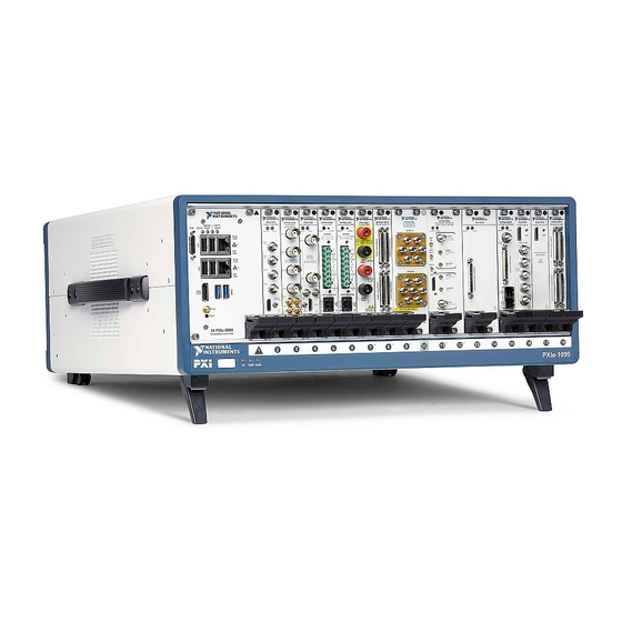
Figures 1-1 and 1-2 show the key features of the PXIe-1095 chassis front and back panels. Figure 1-1 shows the front view of the chassis. Figure 1-2 shows the rear view of the chassis. Refer to Figure 2-2, PXIe-1095 Chassis Vents, for chassis vent locations. © National Instruments | 1-3... - Page 11 Chapter 1 Getting Started Figure 1-1. Front View of the PXIe-1095 Chassis PXIe-1095 PS TEMP System Controller Expansion Slot PXI Express System Controller Slot Backplane Connectors Front Panel LEDs Removable Feet Power Inhibit Switch PXI Express Peripheral Slots (11x) 10 DIP Switch PXI Express Hybrid Peripheral Slots (5x) 11 Chassis Carry Handle PXI Express System Timing Slot...
-
Page 12: Optional Equipment
Replacement Fan Kit A fan kit is available from National Instruments, includes both side and PXI module fan assemblies. Rack Mount Kits Rack mounting kits are available from National Instruments that can accommodate a variety of rack depths. -
Page 13: System Controller Slot
Chapter 1 Getting Started System Controller Slot The system controller slot is Slot 1 of the chassis and is a 2-Link configuration system slot as defined by the CompactPCI Express and PXI Express specifications. It has three system controller expansion slots for system controller modules that are wider than one slot. These slots allow the system controller to expand to the left to prevent the system controller from using peripheral slots. -
Page 14: Hybrid Peripheral Slots
Figure 1-3. PXIe-1095 PCI Express Backplane Diagram 32-bit, 33 MHz PCI Port 8 Port 9 Port 12 Port 13 Station 2 Station 3 PCIe PCIe Switch #1 Switch #2 Station 3 Station 2 Port 13 Port 12 Port 8 PCIe-PCI Bridge © National Instruments | 1-7... -
Page 15: System Timing Slot
Chapter 1 Getting Started System Timing Slot The System Timing Slot is slot 10. The system timing slot will accept the following peripheral modules: • A PXI Express System Timing Module with x8, x4, or x1 PCI Express link to the system slot through a PCI Express switch. -
Page 16: Pxi Local Bus
Measurement & Automation Explorer (MAX). Dynamic routing of triggers (automatic line assignments) is supported through certain National Instruments drivers like NI-DAQmx. Although any trigger line may be routed in either direction, it cannot be Note routed in more than one direction at a time. -
Page 17: System Reference Clock
Chapter 1 Getting Started System Reference Clock The PXIe-1095 chassis supplies PXI_CLK10, PXIe_CLK100, and PXIe_SYNC100 independently driven to each peripheral slot. An independent buffer (having a source impedance matched to the backplane and a skew of less than 250 ps between slots) drives PXI_CLK10 to each slot. You can use this common reference clock signal to synchronize multiple modules in a measurement or control system. -
Page 18: Installation And Configuration
• Live Circuits—Operating personnel and service personnel must not remove protective covers when operating or servicing the chassis. Adjustments and service to internal components must be undertaken by qualified service technicians. During service of this © National Instruments | 2-1... -
Page 19: Chassis Cooling Considerations
• Part Replacement—Only service this equipment with parts that are exact replacements, both electrically and mechanically. Contact National Instruments for replacement part information. Installation of parts with those that are not direct replacements may cause harm to personnel operating the chassis. Furthermore, damage or fire may occur if replacement parts are unsuitable. - Page 20 PXIe-1095 User Manual Figure 2-1. PXIe-1095 Chassis Minimum Cooling Clearances 44.45 mm (1.75 in.) 44.45 mm (1.75 in.) PXIe-1095 TEMP FANS USE ONLY COMPATIBLE RACK MOUNT KITS. COOLING CLEARANCE REQUIRED. SEE MANUAL. 101.60 mm (4.00 in.) © National Instruments | 2-3...
- Page 21 Chapter 2 Installation and Configuration Figure 2-2. PXIe-1095 Chassis Vents PXI Module Air Intake (3x) Timing and Synchronization Upgrade Air Exhaust Vent Power Supply Intake (2x) Timing and Synchronization Upgrade Air Intake PXI Module Air Exhaust Vent Side Air Intake Vent (Right)/Side Air Exhaust Vent (Left) Power Supply Air Exhaust Vent (2x) The side exhaust vent (not shown) is located on the left side of the chassis.
-
Page 22: Chassis Ambient Temperature Definition
Ensure ambient intake temperatures do not exceed the ratings in the Operating Environment section of the PXIe-1095 Specifications. The module and side ambient intake temperatures can be monitored in National Instruments Measurement and Automation Explorer (MAX). -
Page 23: Rack Mounting
Chapter 2 Installation and Configuration Rack Mounting Rack mount applications require optional rack mount kits available from National Instruments. Refer to the instructions supplied with the rack mount kits to install your PXIe-1095 chassis in an instrument rack. You may want to remove the feet or carrying handle from the PXIe-1095 Note chassis when rack mounting. -
Page 24: Connecting The Safety Ground
Observe that all fans become operational and all three front panel LEDs are a steady green. Pressing and holding the Power Inhibit button again for four seconds will return the chassis to standby. © National Instruments | 2-7... -
Page 25: Installing A Pxi Express System Controller
Chapter 2 Installation and Configuration Installing a PXI Express System Controller This section contains general installation instructions for installing a PXI Express system controller in a PXIe-1095 chassis. Refer to your PXI Express system controller user manual for specific instructions and warnings. To install a system controller, complete the following steps: Connect the AC power source to the PXI Express chassis before installing the system controller. -
Page 26: Installing Peripheral Modules
Secure the module front panel to the chassis using the module front-panel mounting screws. Figure 2-5. Installing PXI, PXI Express, or CompactPCI Peripheral Modules Injector/Ejector Handle PXIe Chassis PXI Peripheral Module Injector/Ejector Rail Peripheral Module Front Panel Mounting Screws (2x) © National Instruments | 2-9... -
Page 27: Led Indicators
Chapter 2 Installation and Configuration LED Indicators Figure 2-6 shows the front panel LEDs. Table 2-1 describes the front panel LED states. Refer to Figure 1-1, Front View of the PXIe-1095 Chassis for LED locations. Figure 2-6. Front Panel LEDs PS TEMP FANS Power Supply LED Temperature LED... -
Page 28: Dip Switches
(right) position, Default mode is selected. When this switch is in the on (left) position, Manual mode is selected. Figure 2-7. Backplane DIP Switches Switch #1 (Fan) Switch #2 (PWR) Switch #3 (NC) Switch #4 (NC) © National Instruments | 2-11... -
Page 29: Inhibit Mode
Chapter 2 Installation and Configuration Table 2-3. DIP Switch States Location Switch State Description Off (Right) Set chassis fan mode to Auto. Refer to the Fan Mode section for information. On (Left) Set chassis fan mode to High. Off (Right) Set chassis inhibit mode to Default. -
Page 30: Fan Mode
The configuration steps for single or multiple-chassis systems are the same. Note MAX provides the following chassis information: • Asset information, such as serial number or part number • Chassis number • Voltages, temperatures, and fan speeds • Fan and cooling settings © National Instruments | 2-13... - Page 31 Chapter 2 Installation and Configuration • Number and type of power supplies • Slot details • Chassis self-test • Firmware Update Figure 2-8. Chassis Settings in MAX 2-14 | ni.com...
-
Page 32: Trigger Configuration In Max
Static reservation pre-allocates a trigger line to prevent its configuration by a user program. Dynamic reservation/routing/deallocation is on the fly within a user program based upon National Instruments APIs such as NI-DAQmx. NI recommends dynamic reservations and routing are used whenever possible. If static reservations are required, static reservation of trigger lines can be implemented by the user in MAX through the Triggers tab. -
Page 33: Pxi Trigger Bus Routing
Installation and Configuration PXI Trigger Bus Routing Some National Instruments chassis, including the PXIe-1095, have the capability to route triggers from one bus to others within the same chassis using the Trigger Routing tab in MAX, as shown in Figure 2-9. -
Page 34: Using System Configuration And Initialization Files
Device drivers and other utility software read the file to obtain system pxisys.ini information. The device drivers should have no need to directly read the file. For chassis.ini detailed information regarding initialization files, refer to the PXI Express specification at www.pxisa.org © National Instruments | 2-17... -
Page 35: Maintenance
Always disconnect the AC power cables before cleaning or servicing the Caution chassis. Interior Cleaning Use a dry, low-velocity stream of air to clean the interior of the chassis. Use a soft-bristle brush for cleaning around components. © National Instruments | 3-1... -
Page 36: Exterior Cleaning
Chapter 3 Maintenance Exterior Cleaning Clean the exterior surfaces of the chassis with a dry lint-free cloth or a soft-bristle brush. If any dirt remains, wipe with a cloth moistened in a mild soap solution. Remove any soap residue by wiping with a cloth moistened with clear water. -
Page 37: Removal
Install the new power supply into the chassis in the reverse order of removal. Replace and tighten two #6-32 screws with a Phillips screwdriver. Connect the AC inlet power cable. © National Instruments | 3-3... -
Page 38: Connecting Safety Ground
Chapter 3 Maintenance To meet the Shock and Vibration specifications listed in the PXIe-1095 Specifications, tighten screws to 11.5 in · lb (1.3 N · m) of torque. Connecting Safety Ground Refer to the Connecting the Safety Ground section of Chapter 2, Installation and Configuration. Connecting to Power Source Refer to the Connecting to a Power Source section of Chapter 2, Installation and Configuration. -
Page 39: Installing Replacement Fan Assemblies
Using a Phillips screwdriver, tighten the eight #6-32 mounting screws and #8-32 ground screw into the rear of the chassis. To meet Shock and Vibration specifications listed in the PXIe-1095 Specifications, tighten screws to 11.5 in · lb (1.3 N · m) of torque. © National Instruments | 3-5... - Page 40 Chapter 3 Maintenance Figure 3-2. Replacing Rear Fan Module Fan Harness Plug Rear Chassis Feet (2x) PXIe-1095 Chassis Mounting Screws (8x) PXI Module Fan Assembly Figure 3-3. Internal Fan Harness Fan Receptacle Fan Harness Plug 3-6 | ni.com...
-
Page 41: Replacing The Side Fan Assembly
Using a Phillips screwdriver, tighten the four side fan cover mounting screws to the chassis. To meet Shock and Vibration specifications listed in the PXIe-1095 Specifications, tighten screws to 6.7 in · lb (0.8 N · m) of torque. © National Instruments | 3-7... - Page 42 Figure 3-4. Replacing Side Fan Assembly Chassis Side Fan Cavity Side Fan Cover Side Fan Assembly Side Fan Cover Mounting Screws (4x)
-
Page 43: Appendix A Pinouts
Table A-11 shows the XP4 Connector Pinout for the Hybrid peripheral slots. For more detailed information, refer to the PXI-5 PXI Express Hardware Specification, Revision 2.0. Contact the PXI Systems Alliance for a copy of the specification. © National Instruments | A-1... - Page 44 Appendix A Pinouts System Controller Slot Pinouts Table A-1. XP1 Connector Pinout for the System Controller Slot Pins Signals 3.3V Table A-2. XP2 Connector Pinout for the System Controller Slot 2PETp1 2PETn1 2PERp1 2PERn1 2PETp2 2PETn2 2PETp3 2PETn3 2PERp3 2PERn3 2PERp2 2PERn2 2PETp4...
- Page 45 1PERp6 1PERn6 1PETp7 1PETn7 2PETp0 2PETn0 2PERp0 2PERn0 1PERp7 1PERn7 Table A-4. XP4 Connector Pinout for the System Controller Slot 5Vaux SYSEN# WAKE# ALERT# PXI_TRIG3 PXI_TRIG4 PXI_TRIG5 PXI_TRIG6 PXI_TRIG2 PXI_STAR PXI_CLK10 PXI_TRIG1 PXI_TRIG0 PXI_TRIG7 PXI_LBR6 © National Instruments | A-3...
- Page 46 System Timing Slot Pinouts Table A-5. TP1 Connector Pinout for the System Timing Slot PXIe_DSTARA3+ PXIe_DSTARA3- PXIe_DSTARC4+ PXIe_DSTARC4- PXI_STAR12 PXI_STAR13 PXIe_DSTARB4+ PXIe_DSTARB4- PXIe_DSTARA4+ PXIe_DSTARA4- PXIe_DSTARC5+ PXIe_DSTARC5- PXI_STAR14 PXI_STAR15 PXIe_DSTARB5+ PXIe_DSTARB5- PXIe_DSTARA5+ PXIe_DSTARA5- PXIe_DSTARC6+ PXIe_DSTARC6- PXI_STAR16 PXIe_DSTARB6+ PXIe_DSTARB6- PXIe_DSTARA6+ PXIe_DSTARA6-...
- Page 47 Table A-6. TP2 Connector Pinout for the System Timing Slot PXIe_DSTARC8+ PXIe_DSTARC8- PXIe_DSTARB8+ PXIe_DSTARB8- PXIe_DSTARA8+ PXIe_DSTARA8- PXIe_DSTARC1+ PXIe_DSTARC1- PXIe_DSTARB1+ PXIe_DSTARB1- PXI_STAR0 PXI_STAR1 PXIe_DSTARA1+ PXIe_DSTARA1- PXI_STAR2 PXI_STAR3 PXIe_DSTARC2+ PXIe_DSTARC2- PXI_STAR4 PXI_STAR5 PXIe_DSTARB2+ PXIe_DSTARB2- PXI_STAR6 PXI_STAR7 PXIe_DSTARA2+ PXIe_DSTARA2- PXI_STAR8 PXI_STAR9 PXIe_DSTARC11+ PXIe_DSTARC11- PXIe_DSTARC3+ PXIe_DSTARC3- PXI_STAR10...
- Page 48 Table A-7. XP3 Connector Pinout for the System Timing Slot PXIe_CLK100+ PXIe_CLK100- PXIe_SYNC100+ PXIe_SYNC100- PXIe_DSTARC+ PXIe_DSTARC- PRSNT# PWREN# PXIe_DSTARB+ PXIe_DSTARB- PXIe_DSTARA+ PXIe_DSTARA- SMBDAT SMBCLK MPWRGD* PERST# 1RefClk+ 1RefClk- 1PETp0 1PETn0 1PERp0 1PERn0 1PETp1 1PETn1 1PETp2 1PETn2 1PERp2 1PERn2 1PERp1 1PERn1 1PETp3 1PETn3 1PERp3...
- Page 49 STOP# LOCK# 3.3V FRAME# IRDY# BD_SEL# TRDY# 12 to 14 Key Area AD[18] AD[17] AD[16] C/BE[2]# AD[21] 3.3V AD[20] AD[19] C/BE[3]# IDSEL AD[23] AD[22] AD[26] V(I/O) AD[25] AD[24] AD[30] AD[29] AD[28] AD[27] REQ# 3.3V AD[31] © National Instruments | A-7...
- Page 50 Appendix A Pinouts Table A-9. P1 Connector Pinout for the Hybrid Slot (Continued) BRSVP1A5 BRSVP1B5 RST# GNT# IPMB_PWR HEALTHY# V(I/O) INTP INTS INTA# INTB# INTC# INTD# -12V TRST# +12V A-8 | ni.com...
- Page 51 Table A-10. XP3 Connector Pinout for the Hybrid Slot PXIe_CLK100+ PXIe_CLK100- PXIe_SYNC100+ PXIe_SYNC100- PXIe_DSTARC+ PXIe_DSTARC- PRSNT# PWREN# PXIe_DSTARB+ PXIe_DSTARB- PXIe_DSTARA+ PXIe_DSTARA- SMBDAT SMBCLK MPWRGD* PERST# 1RefClk+ 1RefClk- 1PETp0 1PETn0 1PERp0 1PERn0 1PETp1 1PETn1 1PETp2 1PETn2 1PERp2 1PERn2 1PERp1 1PERn1 1PETp3 1PETn3 1PERp3 1PERn3...
- Page 52 NI Services National Instruments provides global services and support as part of our commitment to your success. Take advantage of product services in addition to training and certification programs that meet your needs during each phase of the application life cycle; from planning and development through deployment and ongoing maintenance.
- Page 53 Appendix B NI Services • Training and Certification—The NI training and certification program is the most effective way to increase application development proficiency and productivity. Visit for more information. ni.com/training – The Skills Guide assists you in identifying the proficiency requirements of your current application and gives you options for obtaining those skills consistent with your time and budget constraints and personal learning preferences.
- Page 54 Symbols ° Degrees. ≥ Equal or greater than. ≤ Equal or less than. Percent. Amperes. Alternating current. ANSI American National Standards Institute. Auto Automatic fan speed control. American Wire Gauge. © National Instruments | G-1...
- Page 55 Glossary backplane An assembly, typically a printed circuit board, with connectors and signal paths that bus the connector pins. Celsius. Cubic feet per minute. Code of Federal Regulations. Centimeters. CompactPCI An adaptation of the Peripheral Component Interconnect (PCI) Specification 2.1 or later for industrial and/or embedded applications requiring a more robust mechanical form factor than desktop PCI.
- Page 56 Hours. Hertz; cycles per second. International Electrotechnical Commission; an organization that sets international electrical and electronics standards. IEEE Institute of Electrical and Electronics Engineers. Mainframe peak current. Inches. inhibit To turn off. © National Instruments | G-3...
- Page 57 Glossary jitter A measure of the small, rapid variations in clock transition times from their nominal regular intervals. Units: seconds RMS. Kilograms. Kilometers. Pounds. Light emitting diode. line regulation The maximum steady-state percentage that a DC voltage output will change as a result of a specified change in input AC voltage (step change from 90 to 132 VAC or 180 to 264 VAC).
- Page 58 PXI system in that it performs the system controller functions, including clock sourcing and arbitration for data transfers across the backplane. Installing such a device into any other slot can damage the device, the PXI backplane, or both. © National Instruments | G-5...
- Page 59 Glossary system reference A 10 MHz clock, also called PXI_CLK10, that is distributed to all clock peripheral slots in the chassis, as well as a BNC connector on the rear of chassis labeled 10 MHz REF OUT. The system reference clock can be used for synchronization of multiple modules in a measurement or control system.
- Page 60 2-5 slot blocker installation, 2-5 LED indicators, 2-10 front panel LED states (table), 2-10, EMC filler panel kit, 1-5 2-11, 2-12 fan module, replacing, 1-5 filler panel installation, 2-5 ground, connecting, 2-6 © National Instruments | I-1...
- Page 61 Index maintenance. See maintenance of PXIe-1095 chassis maintenance of PXIe-1095 chassis, 3-1 optional equipment, 1-5 cleaning rack mounting, 2-5 exterior cleaning, 3-2 safety ground, connecting, 2-6 interior cleaning, 3-1 unpacking, 1-1 preparation, 3-1 service interval, 3-1 static discharge damage (caution), 3-1 rack mounting, 2-5 kit, 1-5 replacement power supply, 1-5...
Need help?
Do you have a question about the PXI EXPRESS PXIe-1095 and is the answer not in the manual?
Questions and answers