
Related Manuals for National Instruments PXI Express PXIe-1071


Summary of Contents for National Instruments PXI Express PXIe-1071
- Page 1 (217) 352-9330 | Click HERE Find the National Instruments PXIe-1071 at our website:...
- Page 2 PXI Express NI PXIe-1071 User Manual NI PXIe-1071 User Manual February 2013 373011D-01 Artisan Technology Group - Quality Instrumentation ... Guaranteed | (888) 88-SOURCE | www.artisantg.com...
- Page 3 11500 North Mopac Expressway Austin, Texas 78759-3504 USA Tel: 512 683 0100 For further support information, refer to the Technical Support and Professional Services appendix. To comment on National Instruments documentation, refer to the National Instruments Web site at and enter ni.com/info the Info Code feedback ©...
- Page 4 Instruments Corporation. National Instruments respects the intellectual property of others, and we ask our users to do the same. NI software is protected by copyright and other intellectual property laws. Where NI software may be used to reproduce software or other materials belonging to others, you may use NI software only to reproduce materials that you may reproduce in accordance with the terms of any applicable license or other legal restriction.
- Page 5 Other product and company names mentioned herein are trademarks or trade names of their respective companies. Members of the National Instruments Alliance Partner Program are business entities independent from National Instruments and have no agency, partnership, or joint-venture relationship with National Instruments.
- Page 6 Operation of this hardware in a residential area is likely to cause harmful interference. Users are required to correct the interference at their own expense or cease operation of the hardware. Changes or modifications not expressly approved by National Instruments could void the user’s right to operate the hardware under the local regulatory rules.
-
Page 7: Table Of Contents
Installing a PXI Express System Controller ..............2-7 Installing Peripheral Modules ..................2-10 Power Inhibit Switch LED Indicator ................2-11 Inhibit Mode Switch ......................2-12 © National Instruments NI PXIe-1071 User Manual Artisan Technology Group - Quality Instrumentation ... Guaranteed | (888) 88-SOURCE | www.artisantg.com... - Page 8 Contents PXI Express System Configuration with MAX ............2-13 PXI-1 System Configuration................2-14 Using System Configuration and Initialization Files ............ 2-15 Chapter 3 Maintenance Service Interval......................3-1 Preparation........................3-1 Cleaning......................... 3-2 Interior Cleaning ..................... 3-2 Exterior Cleaning .................... 3-2 Appendix A Specifications Appendix B Pinouts...
-
Page 9: About This Manual
PCI Express Base Specification, Revision 2.0, PCI Special Interest Group • PXI-5 PXI Express Hardware Specification, Revision 1.0, PXI Systems Alliance © National Instruments NI PXIe-1071 User Manual Artisan Technology Group - Quality Instrumentation ... Guaranteed | (888) 88-SOURCE | www.artisantg.com... -
Page 10: Getting Started
Software media with PXI Platform Services 2.0 or higher ❑ Read Me First: Safety and Electromagnetic Compatibility ❑ Chassis number labels © National Instruments NI PXIe-1071 User Manual Artisan Technology Group - Quality Instrumentation ... Guaranteed | (888) 88-SOURCE | www.artisantg.com... -
Page 11: Key Features
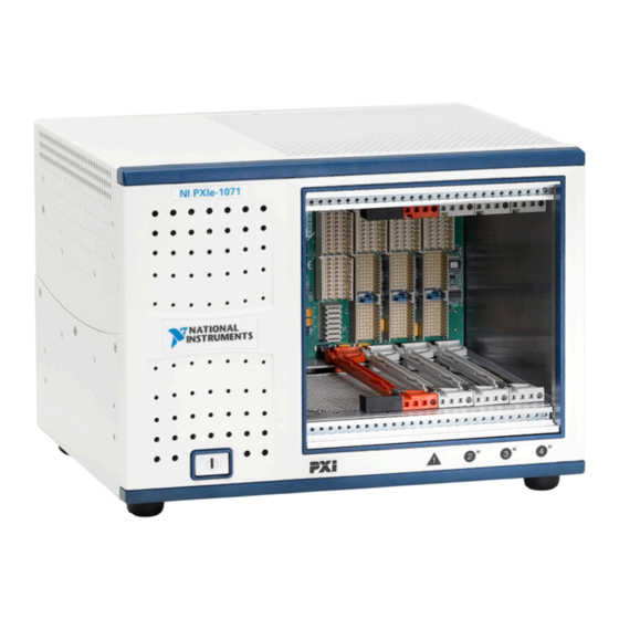
United Kingdom 230 V BS 1363/IEC83 If you are missing any of the items listed in Table 1-1, or if you have the incorrect AC power cable, contact National Instruments. Key Features The NI PXIe-1071 combines a 4-slot PXI Express backplane with a structural design optimized for maximum usability in a wide range of applications. -
Page 12: Chassis Description
4 PXI Express System Controller Slot 9 Chassis Model Name 5 System Controller Expansion Slots Figure 1-1. Front View of the NI PXIe-1071 Chassis © National Instruments NI PXIe-1071 User Manual Artisan Technology Group - Quality Instrumentation ... Guaranteed | (888) 88-SOURCE | www.artisantg.com... - Page 13 Chapter 1 Getting Started 1 Rear Intake Vents 5 Chassis Ground Screw 2 AC Input 6 AUTO/HIGH Fan Speed Selector Switch 3 Power Supply Fan Exhaust 7 Kensington Slot 4 Removable Feet Figure 1-2. Rear View of the NI PXIe-1071 Chassis NI PXIe-1071 User Manual ni.com Artisan Technology Group - Quality Instrumentation ...
-
Page 14: Optional Equipment
4 Removable Foot Figure 1-3. Bottom View of the NI PXIe-1071 Chassis Optional Equipment Contact National Instruments to order the following options for the NI PXIe-1071 chassis. EMC Filler Panels Optional EMC filler panel kits are available from National Instruments. -
Page 15: Slot Blockers
Chapter 1 Getting Started Slot Blockers Optional slot blocker kits are available from National Instruments for improved thermal performance when all slots are not used. Handle/Feet Kit An optional side handle and rubber feet kit is available from National Instruments to provide a handle for portability. -
Page 16: System Controller Slot
32-bit/33 MHz PCI bus to the hybrid slots. Refer to Figure 1-4 for PCI Express and PCI connectivity. © National Instruments NI PXIe-1071 User Manual Artisan Technology Group - Quality Instrumentation ... Guaranteed | (888) 88-SOURCE | www.artisantg.com... -
Page 17: Hybrid Peripheral Slots
Chapter 1 Getting Started By default, the system controller will control the power supply with the PS_ON# signals. A logic low on this line will turn the power supply on. The Inhibit Mode switch on the backplane must be in the Default position for the Note system controller to have control of the power supply. -
Page 18: Pxi Trigger Bus
You can use this common reference clock signal to synchronize multiple modules in a measurement or control system. © National Instruments NI PXIe-1071 User Manual Artisan Technology Group - Quality Instrumentation ... Guaranteed | (888) 88-SOURCE | www.artisantg.com... - Page 19 Chapter 1 Getting Started An independent buffer drives PXIe_CLK100 to each peripheral slot. These clocks are matched in skew to less than 100 ps. The differential pair must be terminated on the peripheral with LVPECL termination for the buffer to drive PXIe_CLK100 so that when there is no peripheral or a peripheral that does not connect to PXIe_CLK100, there is no clock being driven on the pair to that slot.
-
Page 20: Installation And Configuration
Under such conditions, this equipment is unsafe and may ignite the gases or gas fumes. © National Instruments NI PXIe-1071 User Manual Artisan Technology Group - Quality Instrumentation ... Guaranteed | (888) 88-SOURCE | www.artisantg.com... -
Page 21: Chassis Cooling Considerations
Part Replacement—Only service this equipment with parts that are exact replacements, both electrically and mechanically. Contact National Instruments for replacement part information. Installation of parts with those that are not direct replacements may cause harm to personnel operating the chassis. Furthermore, damage or fire may occur if replacement parts are unsuitable. - Page 22 Chapter 2 Installation and Configuration 1 Air Outlets 2 Air Intake Figure 2-1. NI PXIe-1071 Module Cooling Airflow Side View © National Instruments NI PXIe-1071 User Manual Artisan Technology Group - Quality Instrumentation ... Guaranteed | (888) 88-SOURCE | www.artisantg.com...
- Page 23 Chapter 2 Installation and Configuration I e - 1 Power Supply Cooling Intake Vent 4 Backplane Cooling Intake Vent 2 Module Cooling Exhaust Vent 5 Power Supply Cooling Exhaust Vent 3 Module Cooling Intake Vent Figure 2-2. NI PXIe-1071 Vents NI PXIe-1071 User Manual ni.com Artisan Technology Group - Quality Instrumentation ...
- Page 24 (12.70 mm) 1.75 in. On Desktop (44.45 mm) In Electronics Rack 1.75 in. (44.45 mm) Figure 2-3. NI PXIe-1071 Cooling Clearances © National Instruments NI PXIe-1071 User Manual Artisan Technology Group - Quality Instrumentation ... Guaranteed | (888) 88-SOURCE | www.artisantg.com...
-
Page 25: Chassis Ambient Temperature Definition
Rack Mounting Rack mount applications require the optional rack mount kits available from National Instruments. Refer to the instructions supplied with the rack mount kits to install your NI PXIe-1071 chassis in an instrument rack. Refer to Figure A-3, NI Chassis Rack Mount Kit Components. -
Page 26: Connecting Safety Ground
Figure 2-4. © National Instruments NI PXIe-1071 User Manual Artisan Technology Group - Quality Instrumentation ... Guaranteed | (888) 88-SOURCE | www.artisantg.com... - Page 27 Chapter 2 Installation and Configuration I e - 1 System Controller Front Panel Mounting Screws (4×) 3 Injector/Ejector Handle 2 NI PXI Express System Controller 4 NI PXIe-1071 Chassis Figure 2-4. Installing a PXI Express System Controller When you begin to feel resistance, push up on the injector/ejector handle to seat the system controller fully into the chassis frame.
- Page 28 2 NI PXI Express System Controller 3 Injector/Ejector Rail Figure 2-5. NI PXI Express System Controller Installed in an NI PXIe-1071 Chassis © National Instruments NI PXIe-1071 User Manual Artisan Technology Group - Quality Instrumentation ... Guaranteed | (888) 88-SOURCE | www.artisantg.com...
-
Page 29: Installing Peripheral Modules
Chapter 2 Installation and Configuration Installing Peripheral Modules The NI PXIe-1071 chassis accepts a variety of peripheral module types in Caution different slots. To prevent damage to the chassis, ensure that the peripheral module is being installed into a slot designed to accept it. Refer to Chapter 1, Getting Started, for a description of the various slot types. -
Page 30: Power Inhibit Switch Led Indicator
If the inhibit switch LED is red, the system fan has failed, and the chassis has shut down to protect modules from damage due to insufficient cooling. © National Instruments 2-11 NI PXIe-1071 User Manual Artisan Technology Group - Quality Instrumentation ... Guaranteed | (888) 88-SOURCE | www.artisantg.com... -
Page 31: Inhibit Mode Switch
Chapter 2 Installation and Configuration Inhibit Mode Switch On the NI PXIe-1071 backplane is a four-position DIP switch (SW1). Switch 1 of SW1 controls the chassis inhibit mode. (Refer to Figure 2-7.) In its default position (OFF), the PXI Express controller controls the power supply on/off state based on the power switch on the chassis front panel. -
Page 32: Pxi Express System Configuration With Max
KnowledgeBase 3TJDOND8 at ni.com/support The configuration steps for single or multiple-chassis systems are the same. Figure 2-8. Multichassis Configuration in MAX © National Instruments 2-13 NI PXIe-1071 User Manual Artisan Technology Group - Quality Instrumentation ... Guaranteed | (888) 88-SOURCE | www.artisantg.com... -
Page 33: Pxi-1 System Configuration
Chapter 2 Installation and Configuration PXI-1 System Configuration Launch MAX. In the Configuration tree, click the Devices and Interfaces branch to expand it. If the PXI system controller has not yet been configured, it is labeled PXI System (Unidentified). Right-click this entry to display the pop-up menu, then select the appropriate system controller model from the Identify As submenu. -
Page 34: Using System Configuration And Initialization Files
For detailed information regarding chassis.ini initialization files, refer to the PXI Express specification at www.pxisa.org © National Instruments 2-15 NI PXIe-1071 User Manual Artisan Technology Group - Quality Instrumentation ... Guaranteed | (888) 88-SOURCE | www.artisantg.com... -
Page 35: Service Interval
Always wear a grounded wrist strap or equivalent while servicing the chassis. © National Instruments NI PXIe-1071 User Manual Artisan Technology Group - Quality Instrumentation ... Guaranteed | (888) 88-SOURCE | www.artisantg.com... -
Page 36: Cleaning
Chapter 3 Maintenance Cleaning Cleaning procedures consist of exterior and interior cleaning of the chassis and cleaning the fan filter. Refer to your module user documentation for information about cleaning the individual CompactPCI or PXI Express modules. Caution Always disconnect the AC power cable before cleaning or servicing the chassis. Interior Cleaning Use a dry, low-velocity stream of air to clean the interior of the chassis. - Page 37 Efficiency ..........70% typical Power disconnect ........The AC power cable provides main power disconnect. The operating range is guaranteed by design. © National Instruments NI PXIe-1071 User Manual Artisan Technology Group - Quality Instrumentation ... Guaranteed | (888) 88-SOURCE | www.artisantg.com...
- Page 38 Appendix A Specifications DC Output DC current capacity (I Voltage Maximum Current +3.3 V 18 A +5 V 17 A +12 V 17 A -12 V 0.75 A Notes Maximum total usable power is 230 W. The maximum combined power available on +3.3 V and +5 V is 125 W. The maximum combined power available on +3.3 V and +5 V derates linearly to 100 W from 45 °C to 50 °C operating ambient temperature range.
- Page 39 MIL-PRF-28800F Class 2 high temperature limit.) Relative humidity range ......20 to 80%, noncondensing (Tested in accordance with IEC-60068-2-56.) © National Instruments NI PXIe-1071 User Manual Artisan Technology Group - Quality Instrumentation ... Guaranteed | (888) 88-SOURCE | www.artisantg.com...
- Page 40 Appendix A Specifications Storage Environment Ambient temperature range ....-40 to 71 °C (Tested in accordance with IEC-60068-2-1 and IEC-60068-2-2. Meets MIL-PRF-28800F Class 3 limits.) Relative humidity range......5 to 95%, noncondensing (Tested in accordance with IEC-60068-2-56.) Shock and Vibration Operational shock ........30 g peak, half-sine, 11 ms pulse (Tested in accordance with IEC-60068-2-27.
- Page 41 DoC for this product, visit , search by model ni.com/certification number or product line, and click the appropriate link in the Certification column. © National Instruments NI PXIe-1071 User Manual Artisan Technology Group - Quality Instrumentation ... Guaranteed | (888) 88-SOURCE | www.artisantg.com...
- Page 42 EU Customers recycling center. For more information about WEEE recycling centers, National Instruments WEEE initiatives, and compliance with WEEE Directive 2002/96/EC on Waste and Electronic Equipment, visit ni.com/environment/weee National Instruments (RoHS) National Instruments RoHS ni.com/environment/rohs_china (For information about China RoHS compliance, go to ni.com/environment/rohs_china...
- Page 43 For more information about this chassis’ support of hardware modules with 64-bit DMA and/or 32-bit DMA with PAE mode, please visit and enter the Info Code ni.com/info PXI64HANG © National Instruments NI PXIe-1071 User Manual Artisan Technology Group - Quality Instrumentation ... Guaranteed | (888) 88-SOURCE | www.artisantg.com...
- Page 44 Appendix A Specifications Mechanical Overall dimensions Standard chassis Height ........6.97 in. (177 mm) Width........10.12 in. (257 mm) Depth ........8.43 in. (214.2 mm) 0.5 in. (12.7 mm) is added to height when feet are installed. Note Weight ............13.1 lb (5.94 kg) Chassis materials ........Stainless Steel, Extruded Aluminum, Cold Rolled Steel, and PC-ABS...
- Page 45 Module Front Panel 0.96 in. (24.38 mm) 8.43 in. (214.2 mm) Figure A-1. NI PXIe-1071 Chassis Dimensions (Front and Side) © National Instruments NI PXIe-1071 User Manual Artisan Technology Group - Quality Instrumentation ... Guaranteed | (888) 88-SOURCE | www.artisantg.com...
- Page 46 Appendix A Specifications M4 x 0.7 0.96 in. 0.25 in. (6.35 mm) Max, 4x (24.38 mm) 6.49 in. (164.85 mm) 0.69 in. 8.74 in. (222 mm) (17.5 mm) Figure A-2. NI PXIe-1071 Chassis Dimensions (Bottom) NI PXIe-1071 User Manual A-10 ni.com Artisan Technology Group - Quality Instrumentation ...
- Page 47 1 0 7 1 Front Rack Mount Kit 2 NI Chassis Figure A-3. NI Chassis Rack Mount Kit Components © National Instruments A-11 NI PXIe-1071 User Manual Artisan Technology Group - Quality Instrumentation ... Guaranteed | (888) 88-SOURCE | www.artisantg.com...
- Page 48 For more detailed information, refer to the PXI-5 PXI Express Hardware Specification, Revision 2.0. Contact the PXI Systems Alliance for a copy of the specification. © National Instruments NI PXIe-1071 User Manual Artisan Technology Group - Quality Instrumentation ... Guaranteed | (888) 88-SOURCE | www.artisantg.com...
- Page 49 Appendix B Pinouts System Controller Slot Pinouts Table B-1. XP1 Connector Pinout for the System Controller Slot Pins Signals 3.3V Table B-2. XP2 Connector Pinout for the System Controller Slot 3PETp1 3PETn1 3PERp1 3PERn1 3PETp2 3PETn2 3PETp3 3PETn3 3PERp3 3PERn3 3PERp2 3PERn2 4PETp0...
- Page 50 Table B-4. XP4 Connector Pinout for the System Controller Slot 5Vaux SYSEN# WAKE# ALERT# PXI_TRIG3 PXI_TRIG4 PXI_TRIG5 PXI_TRIG6 PXI_TRIG2 PXI_STAR PXI_CLK10 PXI_TRIG1 PXI_TRIG0 PXI_TRIG7 PXI_LBR6 © National Instruments NI PXIe-1071 User Manual Artisan Technology Group - Quality Instrumentation ... Guaranteed | (888) 88-SOURCE | www.artisantg.com...
- Page 51 Appendix B Pinouts Hybrid Slot Pinouts Table B-5. P1 Connector Pinout for the Hybrid Slot REQ64# ENUM# 3.3V AD[1] V(I/O) AD[0] ACK64# 3.3V AD[4] AD[3] AD[2] AD[7] 3.3V AD[6] AD[5] 3.3V AD[9] AD[8] M66EN C/BE[0]# AD[12] V(I/O) AD[11] AD[10] 3.3V AD[15] AD[14] AD[13]...
- Page 52 SYSEN# WAKE# ALERT# 3.3V 3.3V 3.3V PXI_TRIG3 PXI_TRIG4 PXI_TRIG5 PXI_TRIG6 PXI_TRIG2 ATNLED PXI_STAR PXI_CLK10 PXI_TRIG1 PXI_TRIG0 ATNSW# PXI_TRIG7 PXI_LBL6 PXI_LBR6 © National Instruments NI PXIe-1071 User Manual Artisan Technology Group - Quality Instrumentation ... Guaranteed | (888) 88-SOURCE | www.artisantg.com...
- Page 53 Technical Support and Professional Services Log in to your National Instruments User Profile to get ni.com personalized access to your services. Visit the following sections of for technical support and professional services: ni.com • Support—Technical support at includes the ni.com/support following resources: –...
- Page 54 Appendix C Technical Support and Professional Services • System Integration—If you have time constraints, limited in-house technical resources, or other project challenges, National Instruments Alliance Partner members can help. To learn more, call your local NI office or visit ni.com/alliance •...
- Page 55 Equal or less than. Percent. Amperes. Alternating current. ANSI American National Standards Institute. Auto Automatic fan speed control. American Wire Gauge. © National Instruments NI PXIe-1071 User Manual Artisan Technology Group - Quality Instrumentation ... Guaranteed | (888) 88-SOURCE | www.artisantg.com...
- Page 56 Glossary backplane An assembly, typically a printed circuit board, with connectors and signal paths that bus the connector pins. Bayonet Neill Concelman connector; a commonly used coaxial connector. Celsius. Cubic feet per minute. Code of Federal Regulations. Centimeters. CompactPCI An adaptation of the Peripheral Component Interconnect (PCI) Specification 2.1 or later for industrial and/or embedded applications requiring a more robust mechanical form factor than desktop PCI.
- Page 57 International Electrotechnical Commission; an organization that sets international electrical and electronics standards. IEEE Institute of Electrical and Electronics Engineers. Mainframe peak current. © National Instruments NI PXIe-1071 User Manual Artisan Technology Group - Quality Instrumentation ... Guaranteed | (888) 88-SOURCE | www.artisantg.com...
- Page 58 Glossary Inches. inhibit To turn off. jitter A measure of the small, rapid variations in clock transition times from their nominal regular intervals. Units: seconds RMS. Kilograms. Kilometers. Pounds. Light emitting diode. line regulation The maximum steady-state percentage that a DC voltage output will change as a result of a specified change in input AC voltage (step change from 90 to 132 VAC or 180 to 264 VAC).
- Page 59 Installing such a device into any other slot can damage the device, the PXI backplane, or both. © National Instruments NI PXIe-1071 User Manual Artisan Technology Group - Quality Instrumentation ... Guaranteed | (888) 88-SOURCE | www.artisantg.com...
- Page 60 Glossary system reference A 10 MHz clock, also called PXI_CLK10, that is distributed to all clock peripheral slots in the chassis, as well as a BNC connector on the rear of chassis labeled 10 MHz REF OUT. The system reference clock can be used for synchronization of multiple modules in a measurement or control system.
- Page 61 2-6 figure, 2-5 CompactPCI interoperability with NI PXIe-1071 backplane, 1-6 ground, connecting, 2-7 configuration in MAX (figure), 2-13 © National Instruments NI PXIe-1071 User Manual Artisan Technology Group - Quality Instrumentation ... Guaranteed | (888) 88-SOURCE | www.artisantg.com...
- Page 62 (caution), 3-1 chassis initialization file, 2-15 configuration in MAX (figure), 2-13 connecting safety ground, 2-7 National Instruments support and filler panel installation, 2-6 services, C-1 installing a PXI Express system NI PXIe-1071 controller, 2-7...
- Page 63 A-5 XP2 connector (table), B-2 service interval, 3-1 XP3 connector (table), B-3 setting fan speed, 2-6 XP4 connector (table), B-3 © National Instruments NI PXIe-1071 User Manual Artisan Technology Group - Quality Instrumentation ... Guaranteed | (888) 88-SOURCE | www.artisantg.com...
- Page 64 Index system reference clock, 1-9 default behavior (figure), 1-10 unpacking the NI PXIe-1071 chassis, 1-1 specifications, A-7 Web resources, C-1 technical support, C-1 WEEE information, A-6 testing power up, 2-7 training and certification (NI resources), C-1 trigger bus, 1-9 troubleshooting (NI resources), C-1 NI PXIe-1071 User Manual ni.com Artisan Technology Group - Quality Instrumentation ...
Need help?
Do you have a question about the PXI Express PXIe-1071 and is the answer not in the manual?
Questions and answers