Subscribe to Our Youtube Channel
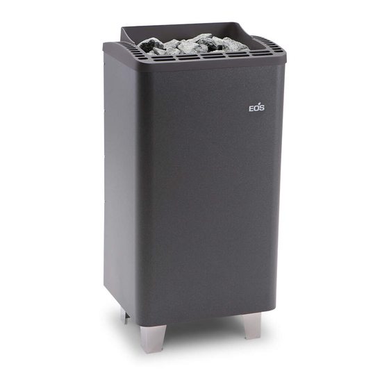
Summary of Contents for EOS Thermo-Tec S
- Page 1 Thermo-Tec S Assembly and operating instruction MADE IN GERMANY IP x4 Druck.-Nr 29343829en / 28.12...
-
Page 2: Table Of Contents
English Table of Contents Intended use ......................3 General notes ......................3 Important notes .......................4 Electrical connection ....................5 Example of a properly connected sauna system ............6 Installation ......................7 Technical data ......................7 Minimum clearances ..................7 Sauna stones ......................9 Maintenance and care ....................9 Service Address: ....................11 Guarantee ......................11 Handling procedures for return shipments (RMA) - Details for all returns ! ..12... -
Page 3: Intended Use
Dear customer General information You have purchased a high-quality technical Please check whether the unit has arrived in per- device with which you will have years of sau- fect condition. Any transport damages should be na fun. This sauna heater was designed and immediately reported to the freight forwarder inspected according to the current European delivering the goods or you should contact the... -
Page 4: General Notes
Important notes Please provide air intake and vent ope- • nings in each sauna cabin. The air intakes Unprofessional installation may cau- • must always be positioned behind the se a re hazard! Please read these instal- sauna heater, approx. 5 to 10 cm above lation instructions carefully. - Page 5 stallation or set-up in a niche, under a sauna heater and the oor. On heaters bench or under a sloping roof. with bases, this clearance is maintained via the base or legs of the device. Do not put the sauna heater into operation •...
-
Page 6: Electrical Connection
Electrical connection place any herbs into the vaporizer holder for essences/herbs. Risk of re! Using the above-mentioned wiring diagram and the information on the wiring circuit ad- hered to the respective control system, your Never add more essences or volatile •... -
Page 7: Example Of A Properly Connected Sauna System
Example of a properly connected sauna system Sensor Saunasteuergerät control unit max. 9 kW N U V W L1 L2 L3 N U V W WB WM N Caution! Always make certain to connect the neutral wire N. 400 V AC 3N 4,5 kW 6 kW 400 V AC 3N... -
Page 8: Installation
Installation Minimum clearances The minimum height of the sauna cabin must be 1.90m on the inside. The vertical clearance between the upper edge of the sauna heating unit and the sauna ceiling is at least 90 cm. Cabin wall Oven safe- Technical data ty grid Voltage: 400 V AC 3N 50 Hz... -
Page 9: Illust
2. Attach connecting line in accordance 5. Fasten the sauna heating unit to the wall with circuit diagram. A circuit diagram is mounting through the hole located on the located in the terminal box. rear edge of the oven using self-tapping 3. -
Page 10: Sauna Stones
Sauna rocks Maintenance and care Sauna stones are a natural product. Check the All sauna heating units are made of low-corro- sauna stones at regular intervals. Aggressive sion material. To enjoy your sauna heating unit sauna essensces can weaken the sauna stones for a long time you should ensure maintainance and cause them to break apart over time. - Page 11 Installation of the sauna heater and control For the installation of sauna heaters, please unit must be undertaken only by an authorized pay attention to the DIN VDE 0100 part 703 ! electrician. Without a documented proof of This standard makes the following statement such installation a warranty is generally void.
-
Page 12: Service Address
Outside of Germany please contact your spe- cialist dealer in case of warranty claims. Direct Service Address: warranty processing with our service depart- EOS Saunatechnik GmbH ment is in this case not possible. Adolf-Weiß-Straße 43 Equipment commissioning date: 35759 Driedorf-Mademühlen, Germany... -
Page 13: Handling Procedures For Return Shipments (Rma) - Details For All Returns
Handling procedures for return shipments (RMA) - Details for all returns ! Dear customer we hope that you will be satis ed with the purchased EOS product. In the rear case if you may have a claim and will need to return a product, please follow the procedures speci ed below.


Need help?
Do you have a question about the Thermo-Tec S and is the answer not in the manual?
Questions and answers