
Related Manuals for EOS Cubo 2


Summary of Contents for EOS Cubo 2
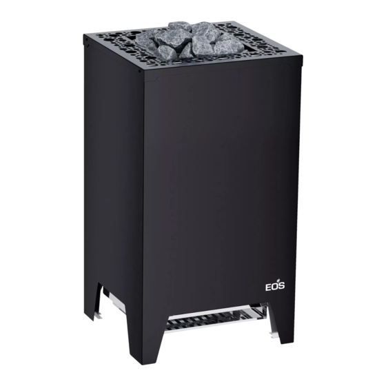
- Page 1 EOS Cubo 2 Sauna heater Styling Typ 1 Styling Typ 2 Installation and operating instruction Made in Germany IPx4 Print no. 2934 5362 en / 38.23 Subject to technical changes...
-
Page 2: Table Of Contents
Contents General safety instructions........................4-9 Identification .............................. 10 ƒ Manufacturer, Copyright, Identification and Product Information........10 ƒ Intended use ............................11 ƒ Foreseeable misuse ........................... 11 ƒ General instructions .......................... 12 Scope of delivery ............................13 Technical data ............................14 ƒ... - Page 3 10. Recycling and Service Address ......................35 11. General terms and conditions of service ..................36...
-
Page 4: General Safety Instructions
General safety instructions 1. General safety instructions Safety levels Safety instructions and important operating instructions are classified. Please familiarise yourself with the following terms and symbols: WARNING Warning Indicates a hazardous situation which, if not avoided, could result in death or serious injury. CAUTION Caution Indicates a hazardous situation which, if not avoided, could result in minor or moderate... - Page 5 General safety instructions 1.1 Mounting and electrical installation These installation instructions are intended for qualified personnel familiar with the laws and regulations applicable to electrical installations at the installation site. Observe the following general safety instructions during mounting, config- uration and commissioning of the product. Risk to life and limb and risk of fire ►...
- Page 6 General safety instructions Risk of burns from hot glass ► Glass surfaces in the cabin become hot while the sauna is in operation. When installing the cabin, ensure that the touchable glass surfaces on the outside of ƒ the cabin may reach a maximum temperature of 76°C. Appropriate protection may need to be installed if required.
- Page 7 General safety instructions Use one of the control units listed below to check and control the sauna heater. ƒ This control unit is fixed to a suitable location on the cabin’s external wall, and the corresponding temperature sensor according to the installation instructions that accompany the control units inside the sauna cabin.
- Page 8 General safety instructions Fire hazard ► Objects placed on the heater or protective guards can easily be ignited and cause fires. Attach the heater guard rail. ƒ Do not place objects on the heater. ƒ Fill the stone grate as directed. ƒ...
- Page 9 ƒ service the system. 1.3 Standards and regulations For an overview of the standards that were observed during design and construction of the sauna heaters, please refer to the individual product’s technical data sheet that can be downloaded from www.eos-sauna.com.
-
Page 10: Identification
2.3 Identification of the device EOS Cubo 2 is an electrically heated sauna heater for Finnish mode available in a variety of output capacities. The heater must be operated with one of the following control units, which are specified in Techni- cal Data of this manual. -
Page 11: X83; Intended Use
This heater is intended solely for the purpose of heating sauna cabins, together with a suitable control unit. EOS Cubo 2 is a floor-standing sauna heater. It is suitable for cabins for commercial and private use. The heater is not suitable for outdoor use! -
Page 12: X83; General Instructions
Identification 2.7 General instructions Please note that an optimal sauna climate can be achieved only if the cabin with its air ƒ inlets and outlets, the sauna heater, and the control unit suit each other. Observe the specifications and information provided by your sauna retailer. ƒ... -
Page 13: Scope Of Delivery
The following parts are included in the scope of delivery: A. Sauna heater B. Accessory pack with four level compensation pads C. Installation and operation manual Example for Styling 2 Cubo 2, Styling 1 Accessories Accessories Item no. Mounting brackets for heater guard rail, brushed stainless steel... -
Page 14: Technical Data
Power extension unit* (PEB unit) not needed PEB 10 For use with the sauna control units EOS Econ series, Compact series, EmoTec series, EmoStyle series, EmoTouch series Leakage current max. 0.75 mA per kW heater output Intended use / area of application... -
Page 15: Electrical Installation
Electrical Installation 5. Electrical installation This chapter describes how EOS Cubo 2 is connected to the power extension units. 5.1 General instructions for electrical installation Ensure that electrical installation is performed in compliance with the standards and legal norms valid in your country. -
Page 16: X83; Terminal Diagram 7,5 - 10 Kw - 400 V
U V W N PE (Gr) Netz / Mains / Réseau / 400 V 3N ~ By 10 and 12 kW unsuitable for Econ controls (power extension unit required from 10 kW) By 12 kW - only suits EOS Compact D18 control unit (single-circuit heaters). -
Page 17: X83; Terminal Diagram 12 Kw - 400 V
N U V W N U V W 1 1 1 L1 L2 L3 Netz / Mains / Réseau / Сеть Netz / Mains / Réseau / Сеть 400 V 3N ~ 400 V 3N ~ Not for EOS Compact D18 control unit... -
Page 18: X83; Electrical Connection - 230 V
Electrical Installation 5.5 Electrical connection of 7.5 - 9 kW to 230 V 1N ~ Saunaofen / sauna heater poêle de sauna / max. 9.0 kW Sensor/ Limiter Saunasteuergerät / Control unit / Boîtier de commande / X Y Z U V W N N L1 L2 L3 N W V U N... -
Page 19: X83; Internal Wiring
Electrical Installation 5.6 Internal wiring 7,5 kW heater output ► 7,5 kW 7,5 kW = 5x 1500 W X Y Z U V W (Gr) 9,0 | 10,0 | 12,0 kW heater output (single-circuit version) ► 9 kW = 6x 1500 W 10 kW = 6x 1666 W *12 kW = 6x 2000 W 12 kW - mind. - Page 20 Electrical Installation 12,0 kW heater output (dual-circuit version) ► 12 kW = 6x 2000 W SSG - sauna control unit, PEB - power extension box...
-
Page 21: X83; Establishing An Electrical Connection
Electrical Installation 5.7 Establishing an electrical connection The connection effects through the terminals in the terminal box at the rear side of the heater. 1. WARNING! If maintenance is carried out on the heater while it is still connected to the mains, this may lead to an electric shock. -
Page 22: Installation
Installation 6. Installation This chapter shows how to install the sauna heater. Prior to installation, air inlets and outlets must be installed in the cabin. It may be necessary to mount additional fans in the inlets/outlets. All protective foils must be removed from the heater. NOTICE Damage due to incorrect mounting location The heater is not suitable for outdoor use. -
Page 23: X83; Dimensions And Safety Gaps
Installation Installation site ► The required cabin volume depends on the heater output. See 2.4 Technical data. Ceiling height of at least 1,90 m ƒ Distance heater – cabin wall min. 4 cm ƒ Distance heater – bench min. 4 cm ƒ... -
Page 24: X83; Air Inlet And Outlet
Installation 6.2 Air inlets and outlets WARNING Fire hazard from overheating The heater can overheat if the air supply is insufficient. There is a risk of death due to fire. Ensure that the air inlets and outlets provide sufficient ventilation. Install a fan if ƒ... -
Page 25: X83; Requirements For Control Unit And Temperature Sensor
Installation Heater is located in the middle of the cabin or in front of a glass wall ► The air inlet must meet the following criteria: Location: Below the heater ƒ A duct directs fresh air to the opening or openings. ƒ... -
Page 26: X83; Connecting Cable
Installation 6.6 Connecting cable The connection is made via terminals in the junction box on the back of the heater. 1. Remove the rear panel. See chapter “Making the electrical connection”. 2. Remove the lid of the junction box. See chapter “Making the electrical connection”. 3. -
Page 27: Commissioning
Commissioning 7. Commissioning Before the heater can be commissioned (switched on), it must be filled with sauna stones, which are available as optional accessories. The heater is switched and controlled via the control unit. A power extension unit (LSG), if availa- ble, will be switched together with the sauna control unit. -
Page 28: X83; Switching The Sauna Heater
Commissioning Filling the rock store ► 1. Wash the stones under running water. 2. WARNING! Sauna stones that are stacked too tightly obstruct the flow of air. The heater could overheat. Place the stones loosely. 3. Fill the stones into the rock store up to the top edge. Leave sufficient space between stones. Notice: In sauna heaters having contact between stones and heating elements fill the stones so that they do no exercise excessive pressure on the heating elements. -
Page 29: X83; Water Splash
Commissioning Water splash ► Before the first water splash can begin, the cabin must be sufficiently heated. The temperature in the cabin is controlled from the control unit via the temperature sensor. The control panel indi- cates when the desired temperature has been reached. WARNING Fire hazard from overheating Incorrectly diluted sauna essences, essential oils or herbs can catch fire. -
Page 30: Maintenance
Maintenance 8. Maintenance This sauna heater is made of low-corrosion material. To ensure a long service life, take care of and perform regular maintenance on your sauna heater. Ensure that openings in the intake area and heat reflectors are never blocked. These can easily become blocked with lint and dust as fresh air is drawn in. -
Page 31: X83; Sauna Stones
Maintenance 8.2 Sauna stones Sauna stones are a product of nature. Sauna stones must be replenished or reshuffled depending on the intensity of use. The process of heating and cooling can make the stones brittle. Particular damage to the sauna stones can be caused by aggressive sauna essences, causing them to disintegrate over time. -
Page 32: X83; Accessories
Service 9. Service 9.1 Replacing the tubular heating element You can replace individual tubular heating elements or the entire heating coil. If the heater is too close to the wall, it may be necessary to move it so that you can access the rear side. - Page 33 Service 6. Disconnect the connection cables from the connection ter- minals.. 7. Unscrew the four hex screws on the heating register. 8. Pull out the junction box with the heating register. Replacing a tubular heating element ► 1. Remove the heating coil. 2.
-
Page 34: X83; Troubleshooting
Service 9.2 Troubleshooting Error Reason Solution It takes the heater a long One or more than one heating Have a technician replace the time to heat up the cabin. element is defective. tubular heating element. There is not enough space Reshuffle the stones. - Page 35 Electronic waste Electronic waste must be disposed of at the designated local collection point for electronic waste. Additional disposal note for commercial users: Further disposal instructions can be found under the link www.eos.sauna.de/recycling Service Address EOS Saunatechnik GmbH Tel: +49 (0)2775 82-514...
- Page 36 The manufacturers General Terms and Conditions of Business, The manufacturer shall assume liability in accordance with the which can be found at www.eos-sauna.com/agb, shall apply in currently applicable statutory regulations. The packaging for all addition to the foregoing terms and conditions of service.
Need help?
Do you have a question about the Cubo 2 and is the answer not in the manual?
Questions and answers