Advertisement
Quick Links
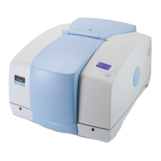
General Purpose Optical Bench w ith
Ex ternal LiTaO
A Spectrum 100 Series or Spectrum 400 Series FT-IR instrument can be fitted with a General
Purpose Optical Bench. The optical bench is supplied with a parabolic mirror assembly, and an
external LiTaO
detector/pre-amplifier module. The optical bench is bolted to the external
3
accessory bracket, which is fitted in the handhold on the right of the instrument.
Fixing bolt
External
beam port
Fixing bolt
Fixing block
Figure 1 General Purpose Optical Bench with External LiTaO
This document describes how to:
Install a window in the right-hand external beam port;
•
•
Fit, and remove, the optical bench;
•
Fit the mirror and detector/pre-amplifier modules to the optical bench;
Configure Spectrum or Spectrum Express software to use an external detector;
•
•
Use Spectrum or Spectrum Express software to select the accessory;
Optimizing the performance of the detector/pre-amplifier;
•
•
Connect another type of detector/pre-amplifier to the instrument.
Detector Accessory
3
LiTaO3 detector /
pre-amplifier module
PerkinElmer Ltd, Chalfont Road, Seer Green,
Beaconsfield, BUCKS, HP9 2FX, United Kingdom.
L1050070A
Mirror assembly
Optical bench
Detector
3
Produced in the UK.
Advertisement

Subscribe to Our Youtube Channel
Related Manuals for PerkinElmer FT-IR


Summary of Contents for PerkinElmer FT-IR
- Page 1 General Purpose Optical Bench w ith Ex ternal LiTaO Detector Accessory A Spectrum 100 Series or Spectrum 400 Series FT-IR instrument can be fitted with a General Purpose Optical Bench. The optical bench is supplied with a parabolic mirror assembly, and an external LiTaO detector/pre-amplifier module.
- Page 2 Detector accessory is supplied for use as an experimental test bed. The user-configurable nature of this product means that PerkinElmer cannot guarantee the level of immunity to external electromagnetic interference (EMI) or the possibility that the product may itself cause interference to other nearby equipment.
-
Page 3: Safe Handling
L1050070A R adiation em itted by the Spectrum 100/ 400 source Caution should be exercised when the beam from an NIR source is directed onto the external LiTaO detector. Unless there is a suitable attenuator in CAUTION place, the detector could be permanently damaged. The NIR source is a quartz halogen bulb that emits ultraviolet, visible and infrared radiation. - Page 4 L1050070A Fitting and Rem oving the Optical Bench In the first instance, the General Purpose Optical Bench is installed by a PerkinElmer Service Engineer, who will install: a right-hand beam moveable mirror and any other internal parts required; a KBr window; and an external accessory bracket in the handhold on the right of the instrument (if not already fitted).
- Page 5 L1050070A 5. Ensure the seal is fitted to the window and is correctly seated (Figure 3). Seal Window Figure 3 Seal fitted to window 6. Fit the window to the main cover from the outside in. Ensure the seal is fully seated and the key on the window lines up with the notch in the main cover.
- Page 6 L1050070A Fitting the optical bench Before you begin, make sure that: The instrument’s external beam port is fitted with a suitable window; • There is at least 500 mm (18 inches) of free bench space to the right of the instrument; •...
- Page 7 L1050070A Screw the two M6 socket head bolts into the threaded fixing positions at the near-left and far-left corners of the optical bench, align the optical bench with the fixing block, and then carefully and evenly tighten the bolts. M6 bolt Detector/preamplifier default fixing positions M6 bolt...
- Page 8 L1050070A Fitting the Detector/ P re-am plifier and M irror M odules Both modules are fixed to the optical bench using M6 bolts. The default fixing positions for the pillars are marked on the optical bench; see Figure 6. Detector/ pre-am plifier m odule Take care not to touch the detector window or any of the circuit-board components of the detector/preamplifier module, as they may be damaged by CAUTION...
- Page 9 L1050070A Figure 8 Fixing the detector/preamplifier module to the bench Ensure that the detector/preamplifier module is fixed to the bench so that the detector is facing the position on the bench where you will fit the mirror module. Detector Gain adjustment potentiometer Figure 9 Detector/preamplifier fitted to the bench The gain adjustment potentiometer (Figure 9) allows adjustment to give an acceptable...
- Page 10 L1050070A M irror m odule Bolt the two pillars and cross-bar that support the parabolic mirror to the optical bench, oriented to that the mirror faces the detector. See Figure 6 for details of fixing position. M6 fixing bolt Vertical alignment adjustment screw M6 fixing bolt Figure 10 Mirror assembly fitted to bench...
- Page 11 L1050070A Browse to C:\Program Files\PerkinElmer\ServiceIR The ServiceIR folder contains a number of utilities, many of which are for use solely by a PerkinElmer Service Engineer. CAUTION If used incorrectly, some utilities could damage the instrument. Double-click S1_Config.exe. The Configuration File Editor utility opens.
- Page 12 L1050070A Select Right Mid in the Select Site pane, select Baseplate in the Select Type pane, and then click Install. The Add Port dialog closes and the external accessory area in the Configuration File Editor is refreshed. Right-click in the right external accessory area. The Add Detector dialog is displayed.
- Page 13 L1050070A R e-instating the configuration file To revert to a standard instrument configuration file: Browse to C:\pel_apps\bin\ The instrument configuration file is named C*****.cfg, where ***** is the five-digit serial number of the instrument. The spectrometer serial number is located on its base casting, in the sample compartment, under the sample accessory baseplate.
- Page 14 L1050070A Select the Beam tab. In the external detector area, click the symbol, so that it becomes NOTE: If an NIR source is being used and the detector type is not either a Custom type or NIR, a warning message is displayed informing you that the detector may be damaged by the NIR beam.
- Page 15 L1050070A To select the external detector in Spectrum Express software: Start Spectrum Express, select the Setup menu and then click Instrument. Select the Setup Instrument BeamPath tab. Select Right external as the Beam Location from the drop-down list. The external LiTaO detector is selected.
-
Page 16: Optimizing Performance
L1050070A Optim izing P erform ance This section describes adjusting the detector alignment and pre-amplifier gain setting and for optimum performance. Start Spectrum, select the Setup menu and then click Instrument. Ensure that the external detector is selected on the beam path tab. If you have Spectrum software, click the “monitor –... - Page 17 L1050070A Connecting Another Type of Detector/ Pre-am plifier to the I nstrum ent For details of how to use another type of detector/preamplifier module with the General Spectrum 100 and 400 Series Right-hand External Purpose Optical Bench, refer to the leaflet Beam Option Spectrum Manuals (L1050069A) provided on the...
Need help?
Do you have a question about the FT-IR and is the answer not in the manual?
Questions and answers