Table of Contents
Advertisement
Quick Links
HPE ProLiant BL460c Gen10 Server Blade
Maintenance and Service Guide
Abstract
This guide describes identification and maintenance procedures, diagnostic tools, specifications
and requirements for hardware components and software. This guide is for an experienced
service technician. Hewlett Packard Enterprise assumes you are qualified in the servicing of
computer equipment, trained in recognizing hazards in products, and are familiar with weight and
stability precautions.
Part Number: 876834-003
Published: April 2018
Edition: 3
Advertisement
Table of Contents

Related Manuals for Hewlett Packard Enterprise ProLiant BL460c Gen10


Summary of Contents for Hewlett Packard Enterprise ProLiant BL460c Gen10
- Page 1 This guide is for an experienced service technician. Hewlett Packard Enterprise assumes you are qualified in the servicing of computer equipment, trained in recognizing hazards in products, and are familiar with weight and stability precautions.
- Page 2 Documentation, and Technical Data for Commercial Items are licensed to the U.S. Government under vendor's standard commercial license. Links to third-party websites take you outside the Hewlett Packard Enterprise website. Hewlett Packard Enterprise has no control over and is not responsible for information outside the Hewlett Packard Enterprise website. Acknowledgments ®...
-
Page 3: Table Of Contents
Contents Illustrated parts catalog................6 Mechanical components........................6 Access panel spare parts......................6 DIMM baffle spare parts......................6 Heatsink blank spare parts....................... 7 Mezzanine assembly spare parts..................... 7 Server blade release lever kit spare parts................7 Serial label pull tab spare parts....................7 Drive blank spare parts......................7 System components.......................... - Page 4 Removing the access panel....................39 Replacing the access panel....................40 Removing and replacing the drive bay options..................40 Removing and replacing a drive blank..................40 Removing and replacing an SFF drive................... 41 Removing and replacing an NVMe drive................41 Removing and replacing the SFF Flash Adapter option............42 Removing and replacing a uFF drive..................42 Removing and replacing DIMM baffles....................43 Removing the DIMM baffles....................
- Page 5 Product QuickSpecs.......................... 81 UEFI System Utilities.........................81 Selecting the boot mode ......................81 Secure Boot..........................82 Launching the Embedded UEFI Shell ..................82 Intelligent Provisioning........................83 HPE Insight Remote Support......................84 USB support............................84 External USB functionality...................... 84 HPE Smart Storage Administrator.....................84 Component identification................. 86 Front panel components........................86 Front panel LEDs and buttons......................87 Front panel LED power fault codes..................
-
Page 6: Illustrated Parts Catalog
Illustrated parts catalog Mechanical components Hewlett Packard Enterprise continually improves and changes product parts. For complete and current supported parts information, see the Hewlett Packard Enterprise PartSurfer website (http://www.hpe.com/ info/partssurfer). Item Description Access panel spare parts on page 6 DIMM baffle spare parts on page 6... -
Page 7: Heatsink Blank Spare Parts
Customer self repair on page 18: mandatory Description Spare part number Drive blank 667276-001 System components Hewlett Packard Enterprise continually improves and changes product parts. For complete and current supported parts information, see the Hewlett Packard Enterprise PartSurfer website (http://www.hpe.com/ info/partssurfer). Heatsink blank spare parts... -
Page 8: Front Panel/Drive Cage Assembly Spare Parts
Item Description Front panel/drive cage assembly spare parts on page 8 System board with base pan spare parts on page 8 Storage controller/NVMe pass-through board spare parts on page 8 System battery spare part on page 9 DIMM spare parts on page 9 —... -
Page 9: System Battery Spare Part
Description Spare part number HPE Smart Array P204i-b SR Controller 877972-001 NVMe pass-through board 877975-001 System battery spare part Customer self repair on page 18: mandatory Description Spare part number System battery 319603-001 DIMM spare parts Customer self repair on page 18: mandatory Description Spare part number 8-GB, 1Gx8 PC4-2666V-R... -
Page 10: Flexiblelom Adapter Spare Parts
Description Spare part number 1.70 GHz Intel Xeon-B 3104 6c 85W 875709-001 1.70 GHz Intel Xeon-B 3106 8c 85W 875710-001 1.80 GHz Intel Xeon-S 4108 8c 85W 875712-001 2.10 GHz Intel Xeon-S 4110 8c 85W 875711-001 2.60 GHz Intel Xeon-S 4112 4c 85W 875714-001 2.20 GHz Intel Xeon-S 4114 10c 85W 875713-001... -
Page 11: Direct Connect Sata Cable Spare Parts
Description Spare part number Direct connect SATA cable 877979-001 Optional server components Hewlett Packard Enterprise continually improves and changes product parts. For complete and current supported parts information, see the Hewlett Packard Enterprise PartSurfer website (http://www.hpe.com/ info/partssurfer). Item Description Drive spare parts on page 12... -
Page 12: Drive Spare Parts
For more information, see Removal and replacement procedures on page 28. Drive spare parts SFF SAS/SATA hard drives Customer self repair on page 18: mandatory Description Spare part number 300 GB, HDD, SAS, 12G, 10K, ST, DS 872735-001 300 GB, HDD, SAS, 12G, 10K, SC, ENT 785410-001 300 GB, HDD, SAS, 12G, 15K, SC, DS, ENT 870792-001... - Page 13 More information Hot-plug drive LED definitions on page 89 SFF SAS/SATA SSDs Customer self repair on page 18: mandatory Description Spare part number 80 GB, SSD, SC, 6G, VE, PLP 805361-001 120 GB, SSD, SC, 6G, VE, PLP 805362-001 120 GB, SSD, SC, 6G, RI, PLP 817061-001 120 GB, SSD, MU, 6G, SC, PLP 817096-001...
- Page 14 Description Spare part number 800 GB, SSD, SC, 6G, VE, PLP 805365-001 800 GB SSD, SC, 6G, LE, PLP 805381-001 800 GB, SSD, SC, 6G, ME, PLP 805389-001 960 GB, SSD, SATA, SC, DS, 6G, RI, DS 869580-001 960 GB, SSD, SC, 6G, RI, DS 868928-001 960 GB, SSD, MU-3, 6G, SC 872520-001...
-
Page 15: Drive Backplane Spare Parts
Description Spare part number 1.2 TB, VE, SC2, PLP 765068-001 1.6 TB, SC2, PLP 765061-001 1.6 TB, LE, SC2, PLP 765065-001 2 TB, LE, SC2, PLP 765066-001 2 TB, VE, SC2, PLP 765069-001 Drive backplane spare parts Customer self repair on page 18: mandatory Description Spare part number SAS/SATA drive backplane... -
Page 16: Mezzanine Card Option Spare Parts
Description Spare part number 150 GB hot-plug SATA SFF M.2 SSD 882402-001 480 GB hot-plug SATA SFF M.2 SSD 882403-001 120 GB SATA UFF M.2 SSD, 2280, 6G 831995-001 150 GB SATA UFF M.2 SSD, 2280, 12G 875835-001 480 GB SATA M.2 SSD, 2280, 6G 875836-001 240 GB SATA M.2 SSD, 2280 875850-001... -
Page 17: Hpe Smart Storage Battery Spare Parts
HPE Smart Storage Battery spare parts Customer self repair on page 18: optional Description Spare part number HPE Z BLc Smart Storage Battery 878640-001 Trusted Platform Module spare parts Customer self repair on page 18: optional Description Spare part number HPE TPM 2.0 872159-001 HPE Smart Storage Battery spare parts... -
Page 18: Customer Self Repair
Hewlett Packard Enterprise (or Hewlett Packard Enterprise service providers or service partners) identifies that the repair can be accomplished by the use of a CSR part, Hewlett Packard Enterprise will ship that part directly to you for replacement. There are two categories of CSR parts: •... - Page 19 (5) jours ouvrés. La pièce et sa documentation doivent être retournées dans l'emballage fourni. Si vous ne retournez pas la pièce défectueuse, Hewlett Packard Enterprise se réserve le droit de vous facturer les coûts de remplacement. Dans le cas d'une pièce CSR, Hewlett Packard Enterprise supporte l'ensemble des frais d'expédition et de retour, et détermine la société...
- Page 20 La mancata restituzione del componente può comportare la fatturazione del ricambio da parte di Hewlett Packard Enterprise. Nel caso di riparazione da parte del cliente, Hewlett Packard Enterprise sostiene tutte le spese di spedizione e resa e sceglie il corriere/vettore da utilizzare.
- Page 21 Hewlett Packard Enterprise podrá cobrarle por el de sustitución. En el caso de todas sustituciones que lleve a cabo el cliente, Hewlett Packard Enterprise se hará cargo de todos los gastos de envío y devolución de componentes y escogerá la empresa de transporte que se utilice para dicho servicio.
- Page 22 Customer Self Repair Veel onderdelen in Hewlett Packard Enterprise producten zijn door de klant zelf te repareren, waardoor de reparatieduur tot een minimum beperkt kan blijven en de flexibiliteit in het vervangen van defecte onderdelen groter is. Deze onderdelen worden CSR-onderdelen (Customer Self Repair) genoemd. Als Hewlett Packard...
- Page 23 CSR de reposição se a peça com defeito deve ser devolvida à Hewlett Packard Enterprise. Nos casos em que isso for necessário, é preciso enviar a peça com defeito à Hewlett Packard Enterprise, você deverá enviar a peça com defeito de volta para a Hewlett Packard Enterprise dentro do período de tempo definido, normalmente em 5 (cinco) dias úteis.
- Page 24 Customer self repair...
- Page 25 Customer self repair...
- Page 26 Customer self repair...
- Page 27 Customer self repair...
-
Page 28: Removal And Replacement Procedures
Removal and replacement procedures Required tools The following tools might be required to perform some procedures: • T-15 Torx screwdriver • No. 1 Phillips screwdriver Safety considerations Before performing service procedures, review all the safety information. Preventing electrostatic discharge To prevent damaging the system, be aware of the precautions you must follow when setting up the system or handling parts. -
Page 29: Symbols On Equipment
Symbols on equipment The following symbols might be found on the equipment to indicate the presence of potentially hazardous conditions. This symbol indicates the presence of hazardous energy circuits or electric shock hazards. Refer all servicing to qualified personnel. WARNING: To reduce the risk of injury from electric shock hazards, do not open this enclosure. -
Page 30: Power Down The Server Blade
When the server blade goes from the standby mode to the full power mode, the system power LED changes from amber to solid green. The health LED flashes green when the Power On/Standby Button service is being initialized. For more information about the system power LED status, see Front panel LEDs and buttons on page 87. -
Page 31: Remove The Server Blade
Remove the server blade CAUTION: To prevent improper cooling and thermal damage, do not operate the server blade enclosure unless all bays are populated with either a component or a blank. Procedure 1. Identify the proper server blade. 2. Power down the server blade on page 30. 3. - Page 32 HPE ProLiant Gen10 server blade. The version information is on the tag on the front of the server blade. For more information on this and other specific firmware and driver requirements, as well as the latest firmware and driver versions, download the latest SPP from the Hewlett Packard Enterprise website (http:// www.hpe.com/servers/spp/download). Procedure 1.
-
Page 33: Remove The Enclosure Connector Cover
Remove the enclosure connector cover Procedure 1. Place the server blade on a flat, level work surface. 2. Remove the enclosure connector cover. Relocate the PEM nut and rubber stopper This procedure is required if the PEM nut and rubber stoppers must be relocated to support the length of the M.2 SSDs being installed. - Page 34 Procedure Power down the server blade on page 30. Remove the server blade on page 31. Place the server blade on a flat, level work surface. Remove the access panel (Removing the access panel on page 39). Remove the left DIMM baffle (Removing the DIMM baffles on page 43). Remove the M.2 interposer board and the M.2 riser board on page 36.
- Page 35 CAUTION: Always install the PEM nut with the thicker edge on top of the M.2 riser and the thinner edge on the bottom of the M.2 riser. Failure to install the PEM nut in the proper orientation can cause damage to the components.
-
Page 36: Remove The M.2 Interposer Board And The M.2 Riser Board
Remove the M.2 interposer board and the M.2 riser board Procedure 1. Power down the server blade on page 30. 2. Remove the server blade on page 31. 3. Place the server blade on a flat, level work surface. 4. Remove the access panel (Removing the access panel on page 39). 5. -
Page 37: Installing The M.2 Riser Board And M.2 Interposer Board
Installing the M.2 riser board and M.2 interposer board The M.2 riser board supports two M.2 SSDs. This server blade does not support mixing M.2 SSD sizes or bus protocols. Prerequisites To install the M.2 SSDs on the M.2 riser board, you need a No. 1 Phillips screwdriver. Procedure Power down the server blade on page 30. - Page 38 Install the M.2 interposer board on the left DIMM baffle. IMPORTANT: MLB is printed on the M.2 interposer board to indicate edge of the board that connects to the system board. When the M.2 interposer board is installed, MLB must face out towards the edge of the server blade.
-
Page 39: Removing And Replacing The Access Panel
11. Replacing the access panel on page 40. 12. Install the server blade on page 31. 13. Power up the server blade on page 29. Removing and replacing the access panel Removing the access panel Procedure 1. Power down the server blade. 2. -
Page 40: Replacing The Access Panel
Replacing the access panel Procedure 1. Align the access panel with the guides on the server blade in all six locations and place the access panel on the server blade. 2. Slide the access panel forward until it clicks into place. 3. -
Page 41: Removing And Replacing An Sff Drive
CAUTION: To prevent improper cooling and thermal damage, do not operate the server blade unless all device bays are populated with either a component or a blank. To replace the blank, slide the blank into the bay until it locks into place. Removing and replacing an SFF drive Procedure 1. -
Page 42: Removing And Replacing The Sff Flash Adapter Option
To replace the NVMe SSD, press the Do Not Remove button to open the release lever. Slide the drive completely into the drive bay and close the release lever. More information NVMe SSD components on page 90 Removing and replacing the SFF Flash Adapter option CAUTION: To prevent improper cooling and thermal damage, do not operate the server blade or the enclosure unless all device bays are populated with either a component or a blank. -
Page 43: Removing And Replacing Dimm Baffles
To replace the component, slide the uFF drive into the bay until it is firmly seated in the adapter and clicks into place. More information SFF flash adapter components and LED definitions on page 91 Removing and replacing DIMM baffles Removing the DIMM baffles The server blade has two DIMM baffles. -
Page 44: Replacing The Dimm Baffles
• DIMM baffle (right side) — If installed, use the blue pull tab to disconnect the HPE Smart Storage Battery cable from the system board. • DIMM baffle (left side) More information Power down the server blade on page 30 Remove the server blade on page 31 Removing the access panel on page 39 Replacing the DIMM baffles... - Page 45 IMPORTANT: When installing each DIMM baffle, be sure that the alignment tabs engage with the side of the server blade. • DIMM baffle (right side) • DIMM baffle (left side) 2. If removed, install the internal USB drive. To locate the internal USB connector, see System board components on page 93. 3.
-
Page 46: Removing And Replacing A Dimm
5. Install the server blade. 6. Power up the server blade. More information Power up the server blade on page 29 Removing and replacing the direct connect SATA cable on page 54 Replacing the access panel on page 40 Install the server blade on page 31 Removing and replacing a DIMM Procedure 1. -
Page 47: Removing And Replacing An Nvdimm
To replace the DIMM, open the DIMM slot latches, and then install the DIMM. Be sure to then replace all other components that were removed for removing the DIMM. More information Power down the server blade on page 30 Remove the server blade on page 31 Removing the access panel on page 39 Removing the DIMM baffles on page 43 Removing and replacing an NVDIMM... -
Page 48: Dimm And Nvdimm Population Information
4. Place the server blade on a flat, level work surface. 5. Remove the access panel (Removing the access panel on page 39). IMPORTANT: When removing a DIMM baffle, do not remove the following options when installed on the DIMM baffle: •... -
Page 49: Nvdimm Relocation Guidelines
The NVDIMM-N Sanitize options are intended to meet the Purge level. For more information on sanitization for NVDIMMs, see the following sections in the HPE 16GB NVDIMM User Guide on the Hewlett Packard Enterprise website (http://www.hpe.com/info/nvdimm-docs): • NVDIMM sanitization policies •... -
Page 50: Recovering Restored Data From An Nvdimm-N Dram
Failure to properly handle DIMMs can damage the DIMM components and the system board connector. For more information, see the DIMM handling guidelines in the troubleshooting guide for your product on the Hewlett Packard Enterprise website: • HPE ProLiant Gen10 (http://www.hpe.com/info/gen10-troubleshooting) •... -
Page 51: Configuring The Server Blade For Nvdimms
Configuring the server blade for NVDIMMs After installing NVDIMMs, configure the server blade for NVDIMMs. For information on configuring settings for NVDIMMs, see the HPE 16GB NVDIMM User Guide on the Hewlett Packard Enterprise website (http:// www.hpe.com/info/nvdimm-docs). The server blade can be configured for NVDIMMs using either of the following: •... -
Page 52: Replacing The M.2 Enablement Option
7. Remove the M.2 riser board from the left DIMM baffle. More information Power down the server blade on page 30 Remove the server blade on page 31 Removing the access panel on page 39 Removing the DIMM baffles on page 43 Replacing the M.2 enablement option Procedure 1. - Page 53 3. Install the M.2 riser board on the left DIMM baffle. To ensure proper installation, be sure that the M.2 riser board aligns with all alignment guides on the air baffle. 4. Install the M.2 interposer board on the left DIMM baffle until it clicks into place. 5.
-
Page 54: Removing And Replacing An M.2 Ssd
Install the server blade on page 31 Removing and replacing an M.2 SSD Prerequisites A No. 1 Phillips screwdriver is required to perform this procedure. Procedure 1. Power down the server blade. 2. Remove the server blade. 3. Place the server blade on a flat, level work surface. 4. -
Page 55: Removing And Replacing The Mezzanine Assembly
Procedure 1. Power down the server blade. 2. Remove the server blade. 3. Place the server blade on a flat, level work surface. 4. Remove the access panel. 5. Remove the direct connect SATA cable. To replace the component, reverse the removal procedure. More information Power down the server blade on page 30 Remove the server blade on page 31... -
Page 56: Replacing The Mezzanine Assembly
More information Power down the server blade on page 30 Remove the server blade on page 31 Removing the access panel on page 39 Replacing the mezzanine assembly Procedure 1. Align the mezzanine assembly with the guide pins, and then install the mezzanine assembly on the system board. -
Page 57: Removing And Replacing The Mezzanine Card Options
4. Install the server blade. 5. Power up the server blade. More information Power up the server blade on page 29 Replacing the access panel on page 40 Install the server blade on page 31 Removing and replacing the mezzanine card options Removing the mezzanine card options Prerequisites A T-15 Torx screwdriver is required to perform this procedure. -
Page 58: Replacing The Mezzanine Card Options
Replacing the mezzanine card options Prerequisites A T-15 Torx screwdriver is required to perform this procedure. Procedure 1. Align the mezzanine card using the appropriate guide pins on the mezzanine assembly. For more information, see Mezzanine connector guide pin locations on page 99. 2. -
Page 59: Removing And Replacing The Flexiblelom Adapter
5. Install the access panel. 6. Install the server blade. 7. Power up the server blade. More information Power up the server blade on page 29 Replacing the access panel on page 40 Install the server blade on page 31 Removing and replacing the FlexibleLOM adapter Procedure 1. -
Page 60: Removing And Replacing A Storage Controller Or Nvme Pass-Through Board
To replace the component, reverse the removal procedure. More information Power down the server blade on page 30 Remove the server blade on page 31 Removing the access panel on page 39 Removing the mezzanine assembly on page 55 Removing and replacing a storage controller or NVMe pass- through board Removing a storage controller or NVMe pass-through board The server blade supports either a storage controller or an NVMe pass-through board at a time, not both. -
Page 61: Replacing A Storage Controller Or Nvme Pass-Through Board
6. Remove the storage controller or NVMe pass-through board. More information Power down the server blade on page 30 Remove the server blade on page 31 Removing the access panel on page 39 Replacing a storage controller or NVMe pass-through board Procedure Back up all server blade data. - Page 62 Remove the access panel. Remove the direct connect SATA cable, if installed. Prepare the storage controller for installation. Align the storage controller with the alignment pins and lower it onto the connector. Close the storage controller handle to seat the storage controller on the connector. Removal and replacement procedures...
-
Page 63: Removing And Replacing The Hpe Smart Storage Battery
Do not disassemble, crush, puncture, short external contacts, or dispose of the battery in fire or water. • Replace only with the Hewlett Packard Enterprise spare battery designated for this product. Dispose of used batteries according to the manufacturer's instructions and local disposal requirements. •... - Page 64 Procedure 1. Power down the server blade. 2. Remove the server blade. 3. Place the server blade on a flat, level work surface. 4. Remove the access panel. 5. If installed, remove the direct connect SATA cable. 6. If installed, remove the internal USB drive. To locate the internal USB connector, see System board components on page 93.
-
Page 65: Replacing The Hpe Smart Storage Battery
Removing the DIMM baffles on page 43 Replacing the HPE Smart Storage Battery Procedure 1. Install the HPE Smart Storage Battery on the right DIMM baffle. 2. Route the cable on the right DIMM baffle. 3. Align and install the DIMM baffle. Press down on the cable connector to fully seat the HPE Smart Storage Battery cable connector to the system board. -
Page 66: Removing And Replacing The Front Panel/Drive Cage Assembly
4. If removed, install the direct connect SATA cable. 5. If removed, install the internal USB drive. To locate the internal USB connector, see System board components on page 93. 6. Install the access panel. 7. Install the server blade. 8. - Page 67 • Remove the storage controller or the NVMe pass-through board (Removing a storage controller or NVMe pass-through board on page 60). • Remove the direct connect SATA cable (Removing and replacing the direct connect SATA cable on page 54). Remove the internal USB drive, if installed. To locate the internal USB connector, see System board components on page 93.
-
Page 68: Removing And Replacing The Sas/Sata Or Nvme Backplanes
Removing the access panel on page 39 Removing and replacing the SAS/SATA or NVMe backplanes Prerequisites A T-15 Torx screwdriver is required to perform this procedure. Procedure Power down the server blade. Remove the server blade. Place the server blade on a flat, level work surface. Remove the access panel. -
Page 69: Removing And Replacing The System Battery
To replace the component, reverse the removal procedure. More information Power down the server blade on page 30 Remove the server blade on page 31 Removing the access panel on page 39 Removing and replacing the system battery If the server blade no longer automatically displays the correct date and time, then replace the battery that provides power to the real-time clock. -
Page 70: Removing And Replacing The Heatsink Blank
IMPORTANT: When removing the left DIMM baffle, do not remove the M.2 enablement option if installed on the DIMM baffle. 6. Locate the system battery on the system board. For more information, see System board components on page 93. 7. Remove the battery. IMPORTANT: Replacing the system board battery resets the system ROM to its default configuration. -
Page 71: Replacing The Heatsink Blank
4. Remove the access panel. 5. Remove the heatsink blank. Retain the heatsink blank for future use. More information Power down the server blade on page 30 Remove the server blade on page 31 Removing the access panel on page 39 Replacing the heatsink blank Procedure 1. -
Page 72: Removing And Replacing The Server Blade Release Lever Assembly
More information Power up the server blade on page 29 Replacing the access panel on page 40 Install the server blade on page 31 Removing and replacing the server blade release lever assembly Removing the server blade release lever assembly Prerequisites A T-15 Torx screwdriver is required to perform this procedure. - Page 73 10. Remove the front panel/drive cage assembly (Removing and replacing the front panel/drive cage assembly on page 66). 11. While holding the system board in place, turn the base pan on its side and remove the two system board screws from the bottom of the base pan. 12.
-
Page 74: Replacing The Server Blade Release Lever Assembly
More information Power down the server blade on page 30 Remove the server blade on page 31 Removing the access panel on page 39 Replacing the server blade release lever assembly Prerequisites A T-15 Torx screwdriver is required to perform this procedure. Procedure Install the server blade release lever bracket. - Page 75 Extend the serial label pull tab. Align the system board, and then slide it into place inside the base pan. Removal and replacement procedures...
- Page 76 Slide the serial label pull tab back into the closed position. While holding the system board in place, turn the base pan on the side and install the two screws on the bottom of the base pan. Place the server blade on a flat, level work surface. IMPORTANT: Install all components in the same configuration before installing the server blade.
-
Page 77: Removing And Replacing The System Board Assembly
11. Install the storage controller or NVMe pass-through board or connect the direct connect SATA cable (Removing a storage controller or NVMe pass-through board on page 60). 12. Install the mezzanine assembly (Replacing the mezzanine assembly on page 56). 13. Install the drives and drive blanks (Removing and replacing the drive bay options on page 40). 14. -
Page 78: Replacing The System Board Assembly
11. Remove the internal USB drive, if installed. To locate the internal USB connector, see System board components on page 93. 12. Remove the storage controller or the NVMe pass-through board (Removing a storage controller or NVMe pass-through board on page 60). 13. -
Page 79: Hpe Trusted Platform Module 2.0 Gen10 Option
15. Install the access panel. 16. Install the server blade. 17. Power up the server blade. 18. Re-enter the server serial number and product ID (Re-entering the server serial number and product ID on page 79). More information Power up the server blade on page 29 Replacing the access panel on page 40 Install the server blade on page 31 Re-entering the server serial number and product ID... -
Page 80: Troubleshooting
Integrated Management Log Messages and Troubleshooting Guide for HPE ProLiant Gen10 and HPE Synergy provides IML messages and associated troubleshooting information to resolve critical and cautionary IML events. To access the troubleshooting resources, see the Hewlett Packard Enterprise Information Library (http:// www.hpe.com/info/gen10-troubleshooting). Troubleshooting... -
Page 81: Diagnostic Tools
Product QuickSpecs For more information about product features, specifications, options, configurations, and compatibility, see the product QuickSpecs on the Hewlett Packard Enterprise website (http://www.hpe.com/info/qs). UEFI System Utilities The UEFI System Utilities is embedded in the system ROM. Its features enable you to perform a wide range of configuration activities, including: •... -
Page 82: Secure Boot
Procedure 1. From the System Utilities screen, select System Configuration > BIOS/Platform Configuration (RBSU) > Boot Options > Boot Mode. 2. Select a setting. • UEFI Mode (default)—Configures the system to boot to a UEFI compatible operating system. • Legacy BIOS Mode—Configures the system to boot to a traditional operating system in Legacy BIOS compatibility mode. -
Page 83: Intelligent Provisioning
The Shell also provides CLI-based commands you can use to obtain system information, and to configure and update the system BIOS. Prerequisites Embedded UEFI Shell is set to Enabled. Procedure 1. From the System Utilities screen, select Embedded Applications > Embedded UEFI Shell. The Embedded UEFI Shell screen appears. -
Page 84: Hpe Insight Remote Support
HPE Insight Remote Support Hewlett Packard Enterprise strongly recommends that you register your device for remote support to enable enhanced delivery of your Hewlett Packard Enterprise warranty, HPE support services, or Hewlett Packard Enterprise contractual support agreement. Insight Remote Support supplements your monitoring continuously... - Page 85 For more information, see HPE Smart Array SR Gen10 Configuration Guide at the Hewlett Packard Enterprise website. Diagnostic tools...
-
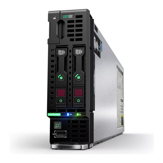
Page 86: Component Identification
Component identification Front panel components Item Description Serial label pull tab HPE c-Class Blade SUV connector (behind the serial label pull tab) Drive bay 2 Drive bay 1 iLO Service port Server blade release lever Server blade release latch The SUV connector and the c-Class Blade SUV Cable are used for some server blade configuration and diagnostic procedures. -
Page 87: Front Panel Leds And Buttons
Front panel LEDs and buttons Item Description Status NIC status LED Solid green = Link to network Flashing green (1 flash per second) = Network active Off = No network activity UID LED Solid blue = Activated Flashing blue: • 1 flash per second = Remote management or firmware upgrade in progress •... -
Page 88: Front Panel Led Power Fault Codes
Item Description Status Health LED Solid green = Normal Flashing green (1 flash per second) = iLO is rebooting Flashing amber = System degraded Flashing red (1 flash per second) = System critical If the health LED indicates a degraded or critical state, review the system IML or use iLO to review the system health status. -
Page 89: Drive Numbering
Drive numbering Depending on the configuration, this server blade can support hard drives, SSDs, NVMe SSDs, and uFF drives (supported in a SFF Flash Adapter) in the drive bays. Depending on the device installed, the bay number might be different. Item Hard drive/SSD bay uFF drive bay NVMe drive bay numbering... -
Page 90: Nvme Ssd Components
Item LED Status Definition Flashing green The drive is doing one of the following: • Rebuilding • Performing a RAID migration • Performing a strip size migration • Performing a capacity expansion • Performing a logical drive extension • Erasing •... -
Page 91: Sff Flash Adapter Components And Led Definitions
Item Component Status Definition Drive removed from the PCIe bus and can be ejected. Power LED Solid green Drive is powered on and configured in system. Do not remove the drive. Flashing green Ejection request pending. Do not remove the drive. Drive removed from the PCIe bus and can be ejected. -
Page 92: Suv Cable Connectors
Item Component Description Locate • Off—Normal • Solid blue—The drive is being identified by a host application. • Flashing blue—The drive firmware is being updated or requires an update. uFF drive ejection latch Removes the uFF drive when released. Do not remove LED •... -
Page 93: System Board Components
Item Connector Description Serial For trained personnel to connect a null modem serial cable and perform advanced diagnostic procedures For connecting up to two USB 2.0 devices Video For connecting a video monitor The USB connectors on the SUV cable do not support devices that require greater than a 500mA power source. System board components Item Description... -
Page 94: System Maintenance Switch
Item Description Storage controller or NVMe pass-through board connector Mezzanine connector 1 (Type A mezzanine only) Mezzanine connector 2 (Type A or Type B mezzanine) Enclosure connector FlexibleLOM connectors (2) SAS/SATA or NVMe backplane Internal USB 3.0 connector HPE Smart Storage Battery connector Direct-connect SATA connector System maintenance switch microSD card slot... -
Page 95: Dimm Slot Locations
CAUTION: Clearing CMOS, NVRAM, or both deletes configuration information. Be sure to configure the server blade properly to prevent data loss. DIMM slot locations DIMM slots are numbered sequentially (1 through 8) for each processor and designate the DIMM slot ID for population rules and spare replacement. -
Page 96: Nvdimm Identification
E = Unbuffered ECC (UDIMM) For more information about product features, specifications, options, configurations, and compatibility, see the product QuickSpecs on the Hewlett Packard Enterprise website (http://www.hpe.com/info/qs). NVDIMM identification NVDIMM boards are blue instead of green. This change to the color makes it easier to distinguish NVDIMMs from DIMMs. - Page 97 RDIMM (registered) Other — For more information about NVDIMMs, see the product QuickSpecs on the Hewlett Packard Enterprise website (http://www.hpe.com/info/qs). NVDIMM 2D Data Matrix barcode The 2D Data Matrix barcode is on the right side of the NVDIMM label and can be scanned by a cell phone or other device.
-
Page 98: Nvdimm Led Identification
NVDIMM LED identification Item LED description LED color Power LED Green Function LED Blue NVDIMM-N LED combinations State Definition NVDIMM-N Power LED NVDIMM-N Function LED (green) (blue) AC power is on (12 V rail) but the NVM controller is not working or not ready. AC power is on (12 V rail) and the NVM controller is ready. -
Page 99: Mezzanine Connector Definitions
State Definition NVDIMM-N Function LED The save operation is in progress. Flashing The NVDIMM-N finished saving and battery is still turned Solid or On on (12 V still powered). The NVDIMM-N has an internal error or a firmware Fast-flashing update is in progress. For more information about an NVDIMM-N internal error, see the IML. -
Page 100: Cabling
Cabling configurations and requirements vary depending on the product and installed options. For more information about product features, specifications, options, configurations, and compatibility, see the product QuickSpecs on the Hewlett Packard Enterprise website (http://www.hpe.com/info/qs). HPE Smart Storage Battery cabling Direct connect SATA cabling... -
Page 101: Using The Hpe C-Class Blade Suv Cable
Using the HPE c-Class Blade SUV Cable The c-Class Blade SUV Cable enables the user to perform server blade administration, configuration, and diagnostic procedures by connecting video and USB devices directly to the server blade. For SUV cable connectors, see "SUV cable connectors." Disconnecting and replacing the SUV cable CAUTION: Before disconnecting the SUV cable from the connector, always squeeze the release buttons on the... -
Page 102: Accessing A Server Blade With Local Kvm
The USB connectors on the SUV cable do not support devices that require greater than a 500mA power source. Numerous configurations are possible. This section offers two possible configurations. For more information, see USB support on page 84. Accessing a server blade with local KVM Prerequisites For this configuration, a USB hub is not necessary. -
Page 103: Accessing Local Media Devices
Accessing local media devices Prerequisites Use the following configuration when configuring a server blade or loading software updates and patches from a USB CD/DVD-ROM. Use a USB hub when connecting a USB CD-ROM drive to the server blade. The USB connectors on the SUV cable do not support devices that require a power source greater than 500mA. -
Page 104: Specifications
Specifications Environmental specifications Specification Value Temperature range — Operating 10°C to 35°C (50°F to 95°F) Nonoperating -30°C to 60°C (-22°F to 140°F) Relative humidity (noncondensing) — Operating 10% to 90% @ 28°C (82.4°F) Nonoperating 5% to 95% @ 38.7°C (101.7°F) Altitude —... -
Page 105: Documentation Feedback
Documentation feedback Hewlett Packard Enterprise is committed to providing documentation that meets your needs. To help us improve the documentation, send any errors, suggestions, or comments to Documentation Feedback (docsfeedback@hpe.com). When submitting your feedback, include the document title, part number, edition, and publication date located on the front cover of the document.
Need help?
Do you have a question about the ProLiant BL460c Gen10 and is the answer not in the manual?
Questions and answers