Table of Contents
Advertisement
Quick Links
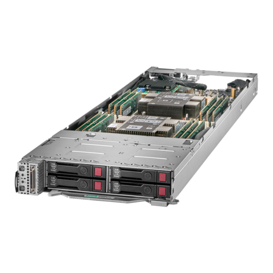
HPE ProLiant XL230k Gen10 Server
User Guide
Abstract
This document is for the person who installs, administers, and troubleshoots servers and storage
systems. Hewlett Packard Enterprise assumes that you are qualified in the servicing of computer
equipment and trained in recognizing hazards in products with hazardous energy levels.
Part Number: 876309-004
Published: April 2019
Edition: 4
Advertisement
Table of Contents

Related Manuals for Hewlett Packard Enterprise HPE ProLiant XL230k Gen10


Summary of Contents for Hewlett Packard Enterprise HPE ProLiant XL230k Gen10
- Page 1 This document is for the person who installs, administers, and troubleshoots servers and storage systems. Hewlett Packard Enterprise assumes that you are qualified in the servicing of computer equipment and trained in recognizing hazards in products with hazardous energy levels.
- Page 2 Documentation, and Technical Data for Commercial Items are licensed to the U.S. Government under vendor's standard commercial license. Links to third-party websites take you outside the Hewlett Packard Enterprise website. Hewlett Packard Enterprise has no control over and is not responsible for information outside the Hewlett Packard Enterprise website. Acknowledgments ®...
-
Page 3: Table Of Contents
Contents Component identification................6 Front panel components........................6 Front panel LEDs and buttons ......................6 Front panel LED power fault codes..................7 Hot-plug drive LED definitions......................8 NVMe drive components and LEDs....................9 Chassis server bay numbering......................10 Chassis I/O module bay numbering....................10 System board components........................ - Page 4 DIMM label identification......................30 Installing a DIMM........................31 Installing the cable retention clip....................... 32 Installing a mezzanine card....................... 34 Installing a PCIe I/O riser card......................38 Installing an I/O riser module......................40 Installing an expansion board into an I/O module..............41 Installing the M.2 SSD enablement option..................44 Installing an HPE Smart Storage Battery..................
- Page 5 Replacing the system battery......................76 Specifications.................... 78 Environmental specifications ......................78 Server specifications......................... 78 Websites..................... 79 Support and other resources..............80 Accessing Hewlett Packard Enterprise Support................80 Accessing updates..........................80 Customer self repair.......................... 81 Remote support..........................81 Warranty information......................... 81 Regulatory information........................82...
-
Page 6: Component Identification
Component identification Front panel components Item Description Serial number/iLO information pull tab SUV connector Drive bay 1 Drive bay 2 Drive bay 3 Drive bay 4 Release latch Front panel LEDs and buttons Component identification... -
Page 7: Front Panel Led Power Fault Codes
Item Description Status Power on/Standby button and System • Solid green = System on power LED • Flashing green (1 Hz/cycle per sec) = System attempting to power on • Solid amber = System in standby • Off = No power present Health LED •... -
Page 8: Hot-Plug Drive Led Definitions
Subsystem LED behavior Memory 3 flashes Riser board PCIe slots 4 flashes FlexibleLOM 5 flashes Removable HPE Smart Array SR Gen10 controller 6 flashes System board PCIe slots 7 flashes Power backplane or storage backplane 8 flashes Power supply 9 flashes Hot-plug drive LED definitions Item LED Status... -
Page 9: Nvme Drive Components And Leds
Item LED Status Definition The drive is doing one of the following: Flashing green • Rebuilding • Performing a RAID migration • Performing a strip size migration • Performing a capacity expansion • Performing a logical drive extension • Erasing •... -
Page 10: Chassis Server Bay Numbering
Chassis server bay numbering Chassis I/O module bay numbering Component identification... -
Page 11: System Board Components
System board components Item Description Internal USB port Processor 2 DIMM slots Processor 2 NVMe riser connector Processor 1 DIMM slots Processor 1 Mezzanine B connector (Processor 2) Mezzanine A connector (Processor 1) SATA cable connector Front panel USB cable connector M.2 cable connector Trusted Platform Module Front panel SUV cable connector... -
Page 12: Processor, Heatsink, And Socket Components
In a single processor configuration, the processor 2 socket dust cover must remain installed during operation. In a single processor configuration, NVMe is not supported. In a single processor configuration, Mezzanine B is not supported. Processor, heatsink, and socket components Item Description Heatsink nuts... -
Page 13: System Maintenance Switch Descriptions
System maintenance switch descriptions Position Default Function Off = iLO 5 security is enabled. On = iLO 5 security is disabled. Reserved Reserved Reserved Off = Power-on password is enabled. On = Power-on password is disabled. 1, 2, 3 Off = No function On = Restore default manufacturing settings Reserved —... -
Page 14: Setup
Setup Setup overview Installation of a server requires the following steps: 1. Install and configure the chassis (Installing the chassis into a rack on page 14). 2. Install any server options (Installing hardware options on page 14). 3. Install the server (Installing the server on page 14). 4. -
Page 15: Powering Up The Chassis
For more information on using these installation methods, see the Hewlett Packard Enterprise website (http:// www.hpe.com/info/ilo). Registering the server To experience quicker service and more efficient support, register the product at the Hewlett Packard Enterprise Product Registration website. -
Page 16: Operations
Operations Power down the server Before powering down the server for any upgrade or maintenance procedures, perform a backup of critical server data and programs. IMPORTANT: When the server is in standby mode, auxiliary power is still being provided to the system. To power down the server, use one of the following methods: •... -
Page 17: Removing A Hot-Plug Drive
Removing a hot-plug drive CAUTION: For proper cooling, do not operate the server without the access panel, baffles, expansion slot covers, or blanks installed. If the server supports hot-plug components, minimize the amount of time the access panel is open. IMPORTANT: The left and right sides of the chassis are oriented 180°... -
Page 18: Removing The Access Panel
4. Place the server on a flat, level work surface. To replace the server, reverse the removal procedure. Removing the access panel IMPORTANT: The left and right sides of the chassis are oriented 180° from each other. Components installed on one side of the chassis must be turned 180° when they are installed on the opposite side. Procedure 1. -
Page 19: Removing A Server Blank
Procedure 1. Power down the server (Power down the server on page 16). 2. Remove the server (Removing the server on page 17). 3. Place the server on a flat, level work surface. 4. Remove the access panel (Removing the access panel on page 18). 5. -
Page 20: Installing A Server Blank
Installing a server blank CAUTION: To prevent improper cooling and thermal damage, do not operate the chassis unless all bays are populated with a component or a blank. IMPORTANT: The left and right sides of the chassis are oriented 180° from each other. Components installed on one side of the chassis must be turned 180°... -
Page 21: Removing The Air Baffle
Removing the air baffle IMPORTANT: The left and right sides of the chassis are oriented 180° from each other. Components installed on one side of the chassis must be turned 180° when they are installed on the opposite side. Procedure 1. -
Page 22: Installing The Air Baffle
To replace the component, reverse the removal procedure. Installing the air baffle IMPORTANT: The left and right sides of the chassis are oriented 180° from each other. Components installed on one side of the chassis must be turned 180° when they are installed on the opposite side. Procedure 1. - Page 23 Procedure 1. Power down the server (Power down the server on page 16). 2. Remove the server (Removing the server on page 17). 3. Place the server on a flat, level work surface. 4. Remove the access panel (Removing the access panel on page 18). 5.
-
Page 24: Hardware Options Installation
Hardware options installation Introduction If more than one option is being installed, read the installation instructions for all the hardware options and identify similar steps to streamline the installation process. WARNING: To reduce the risk of personal injury from hot surfaces, allow the drives and the internal system components to cool before touching them. -
Page 25: Installing An Nvme Drive
3. Install the drive. 4. Determine the status of the drive from the drive LED definitions (Hot-plug drive LED definitions on page Installing an NVMe drive CAUTION: To prevent improper cooling and thermal damage, do not operate the server unless all drive and device bays are populated with either a component or a blank. -
Page 26: Installing A Processor-Heatsink Assembly
4. Observe the LED status of the drive. Installing a processor-heatsink assembly Hewlett Packard Enterprise recommends identifying the processor heatsink module components before performing this procedure. See "Processor, heatsink, and socket components on page 12." IMPORTANT: The left and right sides of the chassis are oriented 180° from each other. Components that are installed on one side of the chassis must be turned 180°... - Page 27 CAUTION: If installing a processor with a faster speed, update the system ROM before installing the processor. To download firmware and view installation instructions, see the Hewlett Packard Enterprise Support Center website. CAUTION: THE CONTACTS ARE VERY FRAGILE AND EASILY DAMAGED. To avoid damage to the socket or processor, do not touch the contacts.
- Page 28 d. Turn the module over and place it on a work surface with the processor facing up. e. Install the dust cover. Install the processor-heatsink assembly: a. Remove the dust cover. b. Locate the Pin 1 indicator on the processor frame and the socket. c.
-
Page 29: Memory Options
10. Install the air baffle. 11. Close the front bracket. 12. Install the access panel. 13. Install the server into the rack. 14. Connect each power cord to the server. 15. Connect each power cord to the power source. 16. Power up the server. Memory options IMPORTANT: This server does not support mixing LRDIMMs and RDIMMs. -
Page 30: Hpe Smartmemory Speed Information
HPE SmartMemory speed information For more information about memory speed information, see the Hewlett Packard Enterprise website (https:// www.hpe.com/docs/memory-speed-table). DIMM label identification To determine DIMM characteristics, see the label attached to the DIMM. The information in this section helps you to use the label to locate specific information about the DIMM. -
Page 31: Installing A Dimm
L = LRDIMM (load reduced) E = Unbuffered ECC (UDIMM) For more information about product features, specifications, options, configurations, and compatibility, see the HPE DDR4 SmartMemory QuickSpecs on the Hewlett Packard Enterprise website (http://www.hpe.com/ support/DDR4SmartMemoryQS). Installing a DIMM CAUTION: To avoid damage to the hard drives, memory, and other system components, the air baffle and drive blanks must be installed when the server is powered up. -
Page 32: Installing The Cable Retention Clip
IMPORTANT: If the DIMM latches are not fully closed, the baffle will not sit properly. Install the air baffle (Installing the air baffle on page 22). 10. Close the front bracket. 11. Install the access panel. 12. Install the server into the chassis (Installing the server on page 14). 13. - Page 33 Center the fastener on the front edge of the cable retention clip to the cable connector. Slide the cable retention clip forward to lock it into place. Hardware options installation...
-
Page 34: Installing A Mezzanine Card
Ensure that the cable retention clip is aligned properly to the mezzanine card. 10. Install the mezzanine card (Installing a mezzanine card on page 34). 11. Install the rear support bracket. 12. Install the access panel (Removing the access panel on page 18). 13. - Page 35 Observe the following requirements when installing a mezzanine card: • Install mezzanine cards in slot A, slots A and B, or neither slot. If you are installing only one mezzanine card, install it only in slot A. See System board components on page 11. •...
- Page 36 Route and connect the cables: • Single mezzanine card configuration • Dual mezzanine card configuration Hardware options installation...
- Page 37 • Single EDR mezzanine with fabric management cable • Dual EDR mezzanines with fabric management cable Hardware options installation...
-
Page 38: Installing A Pcie I/O Riser Card
Internal-External I/O Riser Kit, you must also install HPE XL230k External I/O Module in the chassis. For more information about product features, specifications, options, configurations, and compatibility, see the product QuickSpecs on the Hewlett Packard Enterprise website (http://www.hpe.com/info/qs). Procedure Power down the server (Power down the server on page 16). - Page 39 Remove the access panel (Removing the access panel on page 18). Open the front bracket (Opening the front bracket on page 18). Remove the air baffle (Removing the air baffle on page 21). Remove the rear support bracket (Removing the rear support bracket on page 22). Install the PCIe riser assembly onto the rear bracket.
-
Page 40: Installing An I/O Riser Module
HPE XL230k x8 PCIe Internal-External I/O Riser Kit For more information about product features, specifications, options, configurations, and compatibility, see the product QuickSpecs on the Hewlett Packard Enterprise website (http://www.hpe.com/info/qs). CAUTION: To prevent electrical damage, always power down the server associated with the I/O module before installing the I/O module. -
Page 41: Installing An Expansion Board Into An I/O Module
4. Install the I/O module risers into the bays that correspond to the server bays. For more information, see "Chassis I/O module bay numbering on page 10." 5. If there is a card installed in the I/O module, install the cable for that card. Installing an expansion board into an I/O module IMPORTANT: The left and right sides of the chassis are oriented 180°... - Page 42 Procedure 1. If installed, remove the I/O module from the chassis. 2. Remove the riser cover. 3. Install the expansion board. Hardware options installation...
- Page 43 4. Install the riser cover. 5. Install the riser into the I/O module. Hardware options installation...
-
Page 44: Installing The M.2 Ssd Enablement Option
Installing the M.2 SSD enablement option IMPORTANT: The left and right sides of the chassis are oriented 180° from each other. Components installed on one side of the chassis must be turned 180° when they are installed on the opposite side. Procedure Power down the server (Power down the server on page 16). - Page 45 Align the M.2 backplane adapter, and then secure it with T-10 flat head screws. Align the guide brackets so that each bracket faces the other, and then secure the brackets with pan head screws. Hardware options installation...
- Page 46 10. Install up to two M.2 SSD drives onto the backplane. 11. Install the M.2 backplane. Be sure that the backplane is fully seated and that the guide brackets are closed. Hardware options installation...
- Page 47 12. Connect the cable to the adapter, and then close the bracket. 13. Remove the rear support bracket screws. Hardware options installation...
- Page 48 14. Remove the rear support bracket. a. If a mezzanine card is installed in slot A, remove the mezzanine card while maintaining the cable connection between the mezzanine card and the rear support bracket. b. If the PCIe riser is installed, remove the screw securing the rear support bracket to the PCIe riser bracket, and then remove the rear support bracket.
- Page 49 15. Route and connect the cable to the system board. 16. Install the mezzanine card. Hardware options installation...
- Page 50 17. Install the rear support bracket. IMPORTANT: To prevent damage to the cable when installing the rear support bracket, route the mezzanine cables as pictured. 18. Install the air baffle (Installing the air baffle on page 22). 19. Close the front bracket. 20.
-
Page 51: Installing An Hpe Smart Storage Battery
Installing an HPE Smart Storage Battery NOTE: System ROM and firmware messages may display "energy pack" in place of "Smart Storage Battery." Energy pack refers to both HPE Smart Storage Batteries and HPE Smart Storage Hybrid Capacitors. Procedure Power down the server (Power down the server on page 16). Remove the server (Removing the server on page 17). -
Page 52: Hpe Trusted Platform Module 2.0 Gen10 Option
HPE TPM 2.0 installation is supported with specific operating system support such as Microsoft Windows ® Server 2012 R2 and later. For more information about operating system support, see the product QuickSpecs on the Hewlett Packard Enterprise website (http://www.hpe.com/info/qs). For more information ® ® about Microsoft Windows BitLocker Drive Encryption feature, see the Microsoft website (http:// www.microsoft.com). -
Page 53: Hpe Trusted Platform Module 2.0 Guidelines
Recovery Mode after BitLocker detects a possible compromise of system integrity or system configuration. • Hewlett Packard Enterprise is not liable for blocked data access caused by improper TPM use. For operating instructions, see the TPM documentation or the encryption technology feature documentation provided by the operating system. - Page 54 Follow the instructions on the website to update the system ROM. 3. Update the system ROM. Locate and download the latest ROM version from the Hewlett Packard Enterprise Support Center website (http://www.hpe.com/support/hpesc). To update the system ROM, follow the instructions on the website.
- Page 55 3. Install the TPM cover: a. Line up the tabs on the cover with the openings on either side of the TPM connector. b. To snap the cover into place, firmly press straight down on the middle of the cover. 4.
- Page 56 a. Install the server in the rack, if necessary. b. Install the server in the enclosure. 4. Power up the server. a. Connect the power cords (rack and tower servers). b. Press the Power On/Standby button. Enabling the Trusted Platform Module When enabling the Trusted Platform module, observe the following guidelines: •...
- Page 57 • Enabling or disabling TPM • Clearing the TPM 8. Enable TPM functionality in the OS, such as Microsoft Windows BitLocker or measured boot. For more information, see the Microsoft website. Enabling the Trusted Platform Module as TPM 1.2 Procedure 1.
-
Page 58: Cabling
Cabling Front panel LED board assembly cabling SATA drive cabling Cabling... -
Page 59: M.2 Ssd Cabling
M.2 SSD cabling Mezzanine card cabling Single mezzanine configuration Dual mezzanine configuration NOTE: Mezzanine B is not supported in a single processor configuration. Cabling... - Page 60 Single EDR mezzanine with fabric management cable Dual EDR mezzanines with fabric management cable NOTE: Mezzanine B is not supported in a single processor configuration. Cabling...
-
Page 61: Nvme Backplane Cabling
NVMe backplane cabling NOTE: NVMe is not supported in a single processor configuration. HPE Smart Storage Battery cabling NOTE: This server supports only the HPE Smart Storage Battery. Cabling... -
Page 62: Suv Cable Connectors
SUV cable connectors CAUTION: Before disconnecting the SUV cable from the connector, always squeeze the release buttons on the sides of the connector. Failure to do so can result in damage to the equipment. Item Connector Description Serial For trained personnel to connect a null modem serial cable and perform advanced diagnostic procedures For connecting up to two USB 2.0 devices Video... -
Page 63: Software And Configuration Utilities
Active Health System Viewer (AHSV) is an online tool used to read, diagnose, and resolve server issues quickly using AHS uploaded data. AHSV provides Hewlett Packard Enterprise recommended repair actions based on experience and best practices. AHSV provides the ability to: •... -
Page 64: Hpe Ilo 5
It takes less than 5 minutes to download the Active Health System Log and send it to a support professional to help you resolve an issue. When you download and send Active Health System data to Hewlett Packard Enterprise, you agree to have the data used for analysis, technical resolution, and quality improvements. The data that is collected is managed according to the privacy statement, available at http://www.hpe.com/info/privacy. -
Page 65: Ilo Federation
Any user can view information on iLO Federation pages, but a license is required for using the following features: Group Virtual Media, Group power control, Group power capping, Group configuration, and Group firmware update. For more information about iLO Federation, see the iLO user guide on the Hewlett Packard Enterprise website. iLO Service Port The Service Port is a USB port with the label iLO on ProLiant Gen10 servers and Synergy Gen10 compute modules. -
Page 66: Ilo Restful Api
For more information about the iLO Service Port, see the iLO user guide on the Hewlett Packard Enterprise website. iLO RESTful API iLO includes the iLO RESTful API, which is Redfish API conformant. The iLO RESTful API is a management interface that server management tools can use to perform configuration, inventory, and monitoring tasks by sending basic HTTPS operations (GET, PUT, POST, DELETE, and PATCH) to the iLO web server. -
Page 67: Management Security
This automated server configuration process cuts time from each deployment, making it possible to scale rapid, high-volume server deployments. For more information or to download the STK, see the Hewlett Packard Enterprise website. UEFI System Utilities The UEFI System Utilities is embedded in the system ROM. -
Page 68: Selecting The Boot Mode
• An Embedded UEFI Shell that provides a preboot environment for running scripts and tools. • Boot support for option cards that only support a UEFI option ROM. Selecting the boot mode This server provides two Boot Mode configurations: UEFI Mode and Legacy BIOS Mode. Certain boot options require that you select a specific boot mode. -
Page 69: Launching The Embedded Uefi Shell
• Firmware components and operating systems with boot loaders must have an appropriate digital signature to execute during the boot process. • Operating systems must support Secure Boot and have an EFI boot loader signed with one of the authorized keys to boot. For more information about supported operating systems, see http:// www.hpe.com/servers/ossupport. -
Page 70: Usb Support
For more information, see HPE Smart Array SR Gen10 Configuration Guide at the Hewlett Packard Enterprise website. USB support Hewlett Packard Enterprise Gen10 servers support all USB operating speeds depending on the device that is connected to the server. External USB functionality Hewlett Packard Enterprise provides external USB support to enable local connection of USB devices for server administration, configuration, and diagnostic procedures. - Page 71 • The Firmware Update option in the System Utilities. • The fwupdate command in the Embedded UEFI Shell. • Service Pack for ProLiant (SPP) • HPE online flash components • Moonshot Component Pack Service Pack for ProLiant SPP is a systems software and firmware solution delivered as a single ISO file download. This solution uses SUM as the deployment tool and is tested on supported ProLiant servers.
- Page 72 Use the Firmware Updates option to update firmware components in the system, including the system BIOS, NICs, and storage cards. Procedure 1. Access the System ROM Flash Binary component for your server from the Hewlett Packard Enterprise Support Center. 2. Copy the binary file to a USB media or iLO virtual media.
-
Page 73: Drivers
Download Smart Update Manager for Linux • Download specific drivers To locate the drivers for a server, go to the Hewlett Packard Enterprise Support Center website, and then search for the product name/number. Software and firmware Update software and firmware before using the server for the first time, unless any installed software or components require an older version. -
Page 74: Operating System Version Support
Operational Support Services enable you to choose the right service level, length of coverage, and response time to fit your business needs. For more information, see the Hewlett Packard Enterprise website: https://www.hpe.com/us/en/services/operational.html Utilize the Advisory and Transformation Services in the following areas: •... -
Page 75: Troubleshooting
Integrated Management Log Messages and Troubleshooting Guide for HPE ProLiant Gen10 and HPE Synergy provides IML messages and associated troubleshooting information to resolve critical and cautionary IML events. To access the troubleshooting resources, see the Hewlett Packard Enterprise Information Library (http:// www.hpe.com/info/gen10-troubleshooting). Troubleshooting... -
Page 76: Battery Replacement
Battery replacement Replacing the system battery If the server no longer automatically displays the correct date and time, then replace the battery that provides power to the real-time clock. Under normal use, battery life is 5 to 10 years. WARNING: The computer contains an internal lithium manganese dioxide, a vanadium pentoxide, or an alkaline battery pack. - Page 77 IMPORTANT: Replacing the system board battery resets the system ROM to its default configuration. After replacing the battery, reconfigure the system through UEFI System Utilities (UEFI System Utilities on page 67). To replace the component, reverse the removal procedure. For more information about battery replacement or proper disposal, contact an authorized reseller or an authorized service provider.
-
Page 78: Specifications
Storage maximum humidity of 95% is based on a maximum temperature of 45°C (113°F). Altitude maximum for storage corresponds to a pressure minimum of 70 kPa. For certain approved hardware configurations, the supported system inlet temperature range is extended. The approved hardware configurations for this system are listed on the Hewlett Packard Enterprise website (http://www.hpe.com/servers/ASHRAE). Server specifications... -
Page 79: Websites
Websites General websites Hewlett Packard Enterprise Information Library www.hpe.com/info/EIL Single Point of Connectivity Knowledge (SPOCK) Storage compatibility matrix www.hpe.com/storage/spock Storage white papers and analyst reports www.hpe.com/storage/whitepapers For additional websites, see Support and other resources. Websites... -
Page 80: Support And Other Resources
Hewlett Packard Enterprise Support Center More Information on Access to Support Materials page: www.hpe.com/support/AccessToSupportMaterials IMPORTANT: Access to some updates might require product entitlement when accessed through the Hewlett Packard Enterprise Support Center. You must have an HPE Passport set up with relevant entitlements. Support and other resources... -
Page 81: Customer Self Repair
Customer self repair Hewlett Packard Enterprise customer self repair (CSR) programs allow you to repair your product. If a CSR part needs to be replaced, it will be shipped directly to you so that you can install it at your convenience. -
Page 82: Regulatory Information
Documentation feedback Hewlett Packard Enterprise is committed to providing documentation that meets your needs. To help us improve the documentation, send any errors, suggestions, or comments to Documentation Feedback (docsfeedback@hpe.com). When submitting your feedback, include the document title, part number, edition, and publication date located on the front cover of the document.
Need help?
Do you have a question about the HPE ProLiant XL230k Gen10 and is the answer not in the manual?
Questions and answers