Table of Contents
Advertisement
Quick Links
SW6S
SW6SW
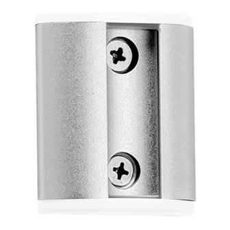
Wall Channel (x1)
! IMPORTANT - Install Systema Wall Channel as per installation instructions.
! Refer to Systema Monitor arm or Monitor Spring Arm Installation Instructions for maximum load advice.
! The manufacturer accepts no responsibility for incorrect installations.
! The Systema Wall Channel is compatible with Systema Monitor Spring Arm: SS and with Systema Monitor Arms: SA13,
SA46, and SA71.
Check what you have received against the component checklist and hardware above.
Step 2. Position Wall plate - Ergonomic Guidelines
Many experts believe that the extended use of any computer screen has the potential to cause serious injury to your eyes,
neck and back. This can be largely avoided by correctly positioning your display.
Height: As a guide, the height (h) of your display should approximately
be as follows:
- Tall Male (Max): 560mm (22")
- Short Male (Min): 368mm (14.5")
- Tall Female (Max): 520mm (20.5")
- Short Female (Min) 356mm (14")
When used with the Systema Monitor Spring Arm, it is
recommended that the bottom of the wall channel is
positioned 50mm above the worksurface to facilitate use by
the largest range of people.
SYSTEMA
Top Cap Screws
Top Cap (x1)
(x2)
(d)
10º -20º
Spring Arm 'SS' Shown
Systema range Technical
M6 x 50mm
Countersunk
Screw (x2)
Systema Monitor
Please refer to the
Specifications for
dimensional details
Distance: For visual comfort, a viewing distance (d) between 500mm
(20") to 750mm (29.5") is recommended.
Viewing angle: Ergonomists recommend that the optimal position
of your display should be slightly below eye level. When looking at
the display's centre the user should have a downward visual angle of
approximately 10°-20°.
Systema | 60mm Wall Channel
Nylon Anchor (x2)
Tools Required:
• Power Drill
• 5.5mm (1/4") Drill Bit
• 8mm (5/16") Drill Bit
• Phillips Head Screwdriver
(h)
50mm (2")
Guidelines based on a
720mm (28.3") high
worksurface
Advertisement
Table of Contents

Related Manuals for Atdec SYSTEMA SW6S


Summary of Contents for Atdec SYSTEMA SW6S
- Page 1 SW6S SYSTEMA Installation Instructions SW6SW Systema | 60mm Wall Channel Component Checklist Wall Channel (x1) Top Cap Screws M6 x 50mm Nylon Anchor (x2) Top Cap (x1) Tools Required: (x2) Countersunk • Power Drill Screw (x2) • 5.5mm (1/4”) Drill Bit •...
- Page 2 Please refer to the Installation Instructions Included with these products. No portion of this document or any artwork contained herein should be reproduced in any way without the express written consent of Atdec Pty Ltd. Due to continuing product development, the manufacturer reserves the right to alter specifications without notice. Published 26.03.14 ©...
- Page 3 Installation Instructions SYSTEMA Systema | Monitor Spring Arm Component Checklist HARDWARE Display Mounting 3/4mm Allen Keys Spacers (x4) Display Mounting Screws Arm Assembly VESA monitor head M4 x 14mm (x1) M4 x 12/16/25mm (x4) Silver Phillips Head Black Phillips Head Mounting Screws Security Screw IMPORTANT INFORMATION: ! IMPORTANT - Install Systema Monitor Spring Arm as per installation instruction.
- Page 4 Step 3. Install VESA monitor head 3.1 Install VESA monitor head as shown. 100mm 75mm VESA monitor head Screen 100mm 75mm M4x12/16/25mm Phillips Head Mounting Screws Spacers (may be required for recessed and uneven surfaces) Step 4. Mount Display VESA monitor head 4.3 Once the VESA monitor head is sitting flush, push the lever down to secure it...
- Page 5 Step 5. Adjust Spring Tension (cont.) 5.2 Push the monitor down to the bottom. If the screen bounces back this may indicate too much tension. Loosen the spring tension 1 turn at a time until no bounce is observed. Once adjustments have been made, move the arm assembly through the full range of movement to ensure it moves freely and holds...
- Page 6 Step 6. Cable Management (cont.) 6.7 Under the Channel Clamp, pull one side of the clip down and push the cable through the gap. Cable Cover Optional Cable Cover Positions 6.8 OPTIONAL (NOTE: The Cable Cover shown, only comes with SP40 or SP75 posts.) To reposition the Cable Cover, pull it straight up and out of the post and insert it into any of the available slots.
- Page 7 Installation Complete No portion of this document or any artwork contained herein should be reproduced in any way without the express written consent of Atdec Pty Ltd. Due to continuing product development, the manufacturer reserves the right to alter specifications without notice. Published 12.02.14 ©...
Need help?
Do you have a question about the SYSTEMA SW6S and is the answer not in the manual?
Questions and answers