Table of Contents
Advertisement
Quick Links
D E G E L M A N
I N D U S T R I E S
B O X
8 3 0 - 2 7 2
I N D U S T R I A L
R E G I N A ,
S K ,
C A N A D A ,
F A X 3 0 6 . 5 4 3 . 2 1 4 0
P H 3 0 6 . 5 4 3 . 4 4 4 7
1 . 8 0 0 . 6 6 7 . 3 5 4 5
D E G E L M A N . C O M
L P
D R I V E ,
STRAWMASTER
S 4 P
3 B 1
OPERATOR MANUAL
& PARTS CATALOG
STRAWMASTER
7 - 50', 70' & 82'
®
Serial Numbers above 7140
142635 v1.6
7000 &
®
Advertisement
Chapters
Table of Contents

Related Manuals for Degelman STRAWMASTER 7 Series


Summary of Contents for Degelman STRAWMASTER 7 Series
- Page 1 OPERATOR MANUAL & PARTS CATALOG 142635 v1.6 STRAWMASTER 7000 & D E G E L M A N I N D U S T R I E S ® B O X 8 3 0 - 2 7 2 I N D U S T R I A L D R I V E , 7 - 50’, 70’...
-
Page 3: Table Of Contents
TABLE OF CONTENTS - OPERATORS SECTION Introduction Safety Safety Information Operation Overview / Preparation Hook-Up Convert to Field Position Suggested Tine Angle Settings Height Adjustment Transporting / Storage Service & Maintenance Service Rephasing the Cylinder Circuits Cylinder Repair Tine Replacement Wheel Hub Repair Troubleshooting TABLE OF CONTENTS - PARTS SECTION... -
Page 5: Introduction
Keep this manual handy for frequent reference and to pass on to new operators or owners. Call your Degelman Dealer if you need assistance, information, or additional copies of the manual. OPERATOR ORIENTATION - The directions left, right, front and rear, as mentioned throughout the manual, are as seen from the tractor drivers’... -
Page 6: Safety
Safety Why is SAFETY important to YOU? 3 BIG Reasons: •Accidents Can Disable and Kill •Accidents Are Costly •Accidents Can Be Avoided SAFETY ALERT SYMBOL The Safety Alert Symbol means: he Safety Alert Symbol identifies important safety messages applied to the Strawmaster and in this ®... - Page 7 SAFETY GENERAL SAFETY YOU are responsible for the safe operation and 1. Read and understand the Operator’s maintenance of your Degelman Strawmaster Manual and all safety signs before ® YOU must ensure that you and anyone else who operating, maintaining or adjusting...
- Page 8 Safety OPERATING SAFETY MAINTENANCE SAFETY 1. Read and understand the Operator’s Manual 1. Review the Operator’s Manual and all safety and all safety signs before using. items before working with, maintaining or operating the Strawmaster ® 2. Stop tractor engine, set park brake, remove ignition key and wait for all moving parts to 2.
- Page 9 Safety HYDRAULIC SAFETY TRANSPORT SAFETY 1. Always place all tractor hydraulic controls in 1. Read and understand ALL the information in the neutral before dismounting. Operator’s Manual regarding procedures and SAFETY when operating the Strawmaster in the ® 2. Make sure that all components in the hydraulic field/yard or on the road.
-
Page 10: Operation
Operation TO THE NEW OPERATOR OR OWNER BRIEF OVERVIEW OF OPERATION The Degelman Strawmaster is designed for • Operating speed will depend on tractor ® effective straw management, weed control, horsepower, environmental conditions and each herbicide application, raking flax residue and particular operation. - Page 11 Operation BREAK-IN PRE-OPERATION CHECKLIST Although there are no operational restrictions on It is important for both personal safety and maintaining trawmaster the good mechanical condition of the machine that this the S when it is new, there are some ® pre-operational checklist be followed: mechanical checks that must be done to ensure the long term integrity of the unit.
-
Page 12: Hook-Up
Operation - Hook-Up HOOK-UP / UNHOOKING The Strawmaster should always be parked on a ® level, dry area that is free of debris and foreign objects. Follow this procedure to hook-up: 1. Clear the area of bystanders and remove foreign objects from the machine and working area. -
Page 13: Convert To Field Position
Operation - Convert to Field Position TO CONVERT TO FIELD POSITION 1. Remove frame transport pins and place in 3. Turn the transport wheel’s spindle over so the holders. Both sides. wheel leans out. Both sides. (NOTE: Hydraulic models have both frame and cylinder transport pins). - Page 14 Operation - Suggested Tine Angle Settings REMEMBER WHEN OPERATING: The following lists suggested tine angle settings. Since there are no standard angles for running the tines, • straw should be dry. the operator may adjust the tine angles as required to •...
-
Page 15: Height Adjustment
Operation - Height Adjustment If trailer height is set correctly it will If trailer is too high... If trailer is too low... be even with harrows and... Front & back tines apply equal pressure Front tines not applying pressure Front tines applying too much pressure ®... - Page 16 Operation TRANSPORT STORAGE Follow this procedure when preparing to transport: After the season’s use, completely inspect all major systems of the machine. Repair or replace any worn 1. Clear the area of bystanders, especially small or damaged components to prevent unnecessary children, before converting into transport down time at the beginning of next season.
-
Page 17: Service & Maintenance
Service & Maintenance Maintenance Checklist SERVICE GREASING Daily - 8 Hours Use an SAE multipurpose grease with extreme • Hydraulic Fluid Leaks pressure (EP) performance. Also acceptable is an • Damaged Hoses SAE multipurpose lithium base grease. • Check Tire Pressure 1. - Page 18 Service & Maintenance TORQUE SPECIFICATIONS HARDWARE/HOSE SPECIFICATIONS CHECKING BOLT TORQUE Unless otherwise stated: • Hardware - Hex, Plated GR5 UNC or P8.8 (metric) The tables shown below give correct torque values • Hydraulic Hoses - 3/8 & 1/2, ends come with for various bolts and capscrews.
-
Page 19: Rephasing The Cylinder Circuits
30-40 seconds. 142368 - Important, Install Pin (2) 4. Repeat this cycle and hold process about 5 times. 142008 - Degelman - 6” x 25-3/4” (2) 143162 - Manual Holder Decal (1) 142557 - Reflector, Amber - 9” (2) 142556 - Reflector, Red - 9”... -
Page 20: Cylinder Repair
Service & Maintenance HYDRAULIC CYLINDER REPAIR 5. Take the plastic removal ring from the seal kit: PREPARATION Types of Cylinders a) Straighten the ring and remove any kinks or When cylinder repair (Wire Ring / Threaded Head) excessive curl to make installation easier and is required, clean off prevent it from falling out. - Page 21 Service & Maintenance 8. Remove locknut, piston and head from rod. 11. b) Tighten the band clamp to ensure the wire ring is fully seated. Then, loosen the clamp Piston Seal (2pcs) approx. 1/2 a turn to allow band clamp to slide Wear Ring during fi...
- Page 22 Service & Maintenance REPAIRING A THREADED HEAD CYLINDER REPAIRING A THREADED HEAD CYLINDER Set Screw Style Locking Ring Style Barrel Barrel Set Screw Locking Gland Ring Lock Piston U-Cup Wear Dual Seal Seal Piston Ring O-Rings Seal Wiper Piston Seals Seal (Style may vary, Lock...
-
Page 23: Tine Replacement
Service & Maintenance - Tine Replacement TINE REPLACEMENT Note: Tines must be replaced when worn down DISASSEMBLY: to 16 in. or less in length. Tines may be replaced Follow this procedure one pipe row at a time so while the machine is in transport position, or field pipes do not get mixed up, or number each pipe position. -
Page 24: Wheel Hub Repair
Service & Maintenance WHEEL HUB REPAIR COMMON WHEEL AND IMPORTANT Be sure to block up unit HUB COMPONENTS securely before removing tires. Spindle Dust Seal Inner Cone DISASSEMBLY Inner Cup 1. Carefully pry off dust cap. Outer Cup 2. Remove cotter pin from nut. Outer Cone Washer 3. -
Page 25: Troubleshooting
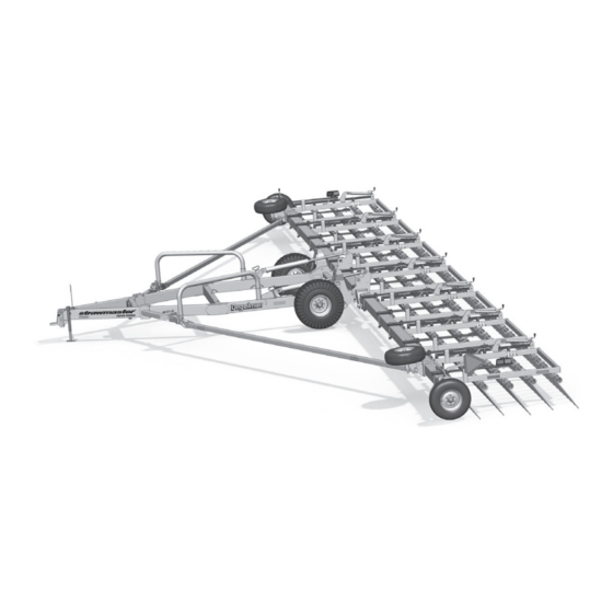
Troubleshooting TROUBLESHOOTING In the following section, we have listed some of the problems, causes and solutions that you may encounter. If you encounter a problem that is difficult to solve, even after having read through this troubleshooting section, please call your local dealer or distributor. Before you call, have this manual and the serial number from your unit ready. - Page 26 General Overview End Wheel 10’ Harrow Section Transport Wheel Right Right Wing Truss Arm Beam Trailer Wheel Swing Arm Pipe Center Beam Auto-Fold Latch Auto-Fold Cylinder Trailer Swing Arm Pipe Cross Joint Trailer Wheel Auto-Fold Latch Left Wing Beam Left Truss 10' 10' 10' 10' 10' 10'...
-
Page 27: Warranty
Parts Section - Table of Contents General Overview 22-23 Wing Beam & Truss Arms Trailer Components & Auto-Fold Cylinder 25-26 Auto-Fold Latch Components Trailer Wheel Components & Cylinder Center Beam Joint Components Transport Wheel & Truss Arm Brackets Transport Wheel Components End Wheel Components &... -
Page 28: 142557 - Reflector, Amber - 9
Wing Beams & Truss Arms WING BEAM (Model Specific) 244385 - Wing beam, 82’ model (2) 243302 - Wing beam, 70’ model (2) 243295 - Wing beam, 50’ model (2) 82’ 70’ 50’ Note: 50’ models require an end wheel plate. 243088 - Extension, 10’... - Page 29 Trailer Components 243005 - Trailer, SM7000 (1) 243174 - Trailer, SM7 (1) 132030 - Jack, Sidewind - 5,000 lbs (1) 143117 - Hose holder, Flexible (1) (extra hoses - hyd. option) 118483 - Nut, 1/4 (4) 143111 - Hose holder, Flexible (1) 118555 - Flat washer, 1/4 (8) 118123 - Bolt, 1/4 x 1 (4) -OR-...
-
Page 30: 142556 - Reflector, Red - 9
132040 - Sidewind Jack 142008 - Decal, Mount (1) 7,000 lbs (2) Degelman - 6”x 25-3/4” (2) JACK MOUNT ASSEMBLY (82’ Only) 118516 - Flat washer, 3/4 (2) 118630 - Bolt, Bent - 3/4 x 12-1/2 (1) 118422 - Lock nut, 3/4 (1) 112”... - Page 31 Auto-Fold Latch • Insert the swing arm pipe into socket. • Rotate the pipe forward so it connects with the centre of the slot on the latch. • You might have to move the latch arm back & forth in the slotted bolt holes to align.
- Page 32 Trailer Wheel Components & Cylinder TRAILER WHEEL COMPONENTS (Left Side Shown) NOTE: Strawmaster ® can have either manual Manual Adjustment Models or hydraulic adjustment. Trailer height & tine 132016 - Ratchet jack (2) angle can be set by ratchet jacks or hydraulics. c/w 132032 - Pin, 2-1/8”...
- Page 33 Trailer Wheel Spindle & Center Beam Joint 240387 - HUB/SPINDLE ASSEMBLY, TRAILER WHEEL - H812 131707 - Hub CTD 812 - c/w Cups & Studs (1) 131706 - Hub Cap - CTD812 (1) 131708 - Replacement Stud (1) 131180 - Bearing Cup #3720 (1) 118835 - Cotter Pin 3/16 x 1-1/2 (1) 131295 - Bearing Cone #3767 (1) 118423 - Slotted Nut 1-14 UNS (1)
- Page 34 Transport Wheel & Truss Arm Brackets 131709 - Wheel Nut 9/16 x 18 UNF (6) Wheel Assembly, Transport wheel (see details on next page) Previously 118914 - Wheel Bolt, 9/16 - 18 UNF (6) 118651 - Jam nut, 9/16” UNF (6) 131348 - Hub/Spindle Assembly, Transport wheel - H618 (2) 118074 - Bolt, 1”x 4”...
- Page 35 Transport Wheel Components WHEEL ASSEMBLY, TRANSPORT WHEEL PREVIOUS Models with Serial Numbers: SM8293 and prior Models with Serial Numbers: SM8294 and up 50’ 50’ 70’ 131600 - Transport wheel Assembly (2) Tire Pressure 131509 - Transport Wheel Assembly (2) Tire Pressure c/w..
- Page 36 End Wheel Assembly Components END WHEEL ASSEMBLY (Left Side Shown) NOTE: Strawmaster ® can have either manual or hydraulic adjustment. Trailer height & tine angle can be set by manual jacks or hydraulics. Manual Adjustment End Wheel Models 132023 - Jack, Sidewind - 10” (not shown, same pins/hdw) Hydraulic End Wheel Cylinder Models - or -...
- Page 37 End Wheel Components END WHEEL COMPONENTS 118126 Bolt, 1/2” x 4” (1) 131324 - Hub/Spindle Assembly, End wheel - H618 131322 - Spindle, 12 (1) (comes with slotted nut) 131026 - Dust seal (1) 131022 - Bearing. Cone - 1.75” ID (1) 131023 - Bearing, Cup - 3.265”...
- Page 38 Harrow Section Components - 5 Row 6’ HARROW SECTION ASSEMBLY OVERVIEW 244397 - Harrow Section Frame - 6’ 6’ HARROW SECTION - PIPES For Straight Harrow Section Frame - 6’ 244400 - Pipe, 19” offset (1) 244401 - Pipe, 23” offset (1) 244402 - Pipe, 15”...
-
Page 39: 142823 - Tine Gauge Decal
Harrow Section Components - 5 Row TINE ANGLE LINK BAR - TYPICAL Manual Jack Hydraulic Jack Connection Connection 118625 - Bolt, 5/8” x 2” UNF (5) 118700 - Lock nut, 5/8” UNF (5) 14 3/4” 14 3/4” 243060 - Link bar, 5 hole (1) 142823 - Tine Gauge Decal (1) 244017 - Indicator pointer (1) - Page 40 Harrow Section Components - 7 Row 10’ HARROW SECTION OVERVIEW - 7 ROW 6’ HARROW SECTION OVERVIEW - 7 ROW 244951 - Harrow Section Frame, 6’ - 7 Row 244771 - Harrow Section Frame, 10’ - 7 Row TINE ANGLE LINK BAR COMPONENTS - 7 ROW 118625 - Bolt, 5/8”...
- Page 41 Harrow Section Components - 7 Row 7 ROW HARROW-FRAME MOUNTING COMPONENTS Note: Flat side faces up. In 118094 - Bolt, 5/8” x 4” (4) some locations, a hydraulic 118630 - Bolt, Bent - 3/4” holder is placed between the x 12-1/2” (2) 650250 - Cast Shank Spring bar and this Bolt Bar.
-
Page 42: 142556 - Reflector, Red - 9
Harrow Section Layout & Tines HARROW SECTION LAYOUT OVERVIEW 10' 10' 10' 10' 10' 10' 10' 10' 10' 10' 10' 10' 10' 10' 10' 10' 10' 10' Harrow Frame Spacing - 5 Row Models Harrow Frame Spacing - 7 Row Models 19-3/4”... - Page 43 Rephasing Cylinder Components MONARCH REPHASING CYLINDERS IMPORTANT: To ensure optimum performance, all Monarch Hydraulic Cylinder Seal Kit Pin Kit entrapped air must be purged from the rephasing Cylinder# Description cylinder systems frequently. Follow the “Rephasing 123630 2-1/2” x 8 x 1-1/8 “R” 123642 123641 the Cylinder Circuits”...
- Page 44 Auto-Fold Cylinder Hydraulic Hose Routing AUTO-FOLD CYLINDER HOSE ROUTING - All Models (Except 82’ - 7 Row) 123090 - Cylinder-Monarch, 3-1/2” x 31” x 2” (2) 123240 - Cylinder-Monarch, 4” x 31” x 2” (2) - 82’ - 7 Row Model 126567 - Hose, 3/8 x 183 (2) 126600 - Hose, 3/8 x 174 (1) 126599 - Hose, 3/8 x 140 (1)
- Page 45 Lift Cylinder Hydraulic Hose Routing (Optional) Hydraulic Fittings 141581 - Quick Coupler-m - 3/4 ORB Previous Fitting 141515 - Connector, 3/4 JIC-m x ORB 141580 - 90° El, 3/4 JIC-m 141501 - Tee, 3/4 JIC-m x ORB 2-1/2 (2) 141504 - 90° Elbow, 3/4 JIC-m x ORB IMPORTANT: To ensure optimum performance, all entrapped air must be purged from the rephasing Hydraulic Cylinders...
- Page 46 Rephasing Hydraulics 50’, 70’ & 82’ Models (Optional) Hydraulic Fittings Note: Numbers vary depending on the number of 50ft rephasing hydraulic cylinders. 70ft 141581 - Quick Coupler-m - 3/4 ORB 82ft 141515 - Connector, 3/4 JIC-m x ORB 141504 - 90° Elbow, 3/4 JIC-m x ORB Rephasing Cylinders Hydraulic Hoses Note: Smallest Cylinder (2-1/2”) is always...
- Page 47 Rephasing Hydraulics 50’, 70’ & 82’ Models (Optional) Hose Support Positioning Hose Clamps Install hose support Install hose 243846 - 4 Hose Clamp rings on the outside clamps of the center beam’s behind the cylinder lugs. cast shank Previously bolt bar. used for last two hoses on End Sections...
- Page 48 Electrical Components & Routing Electrical Layout Wiring Assembly - 50’ Wiring Assembly - 70’/82’ 244151 - Wiring Harness (1) 244150 - Wiring Harness (1) & Components (4-wire light with brake function) 7 POLE PLUG 7 Pole WHITE Ground Plug BROWN Tail/Running YELLOW Left High FL...
- Page 49 Previous - Electrical Components & Routing Previous Electrical Wiring Assembly - 50’ SM Models Wiring Assembly - 82’ & 70’ SM Models 244141 - Wiring Harness, 244140 - Wiring Harness, Layout & Components LIGH18-48-40 (1) LIGH18-58-50 (1) (3-wire light w/o brake function) 7 POLE PLUG WHITE 7 Pole...
- Page 50 It is the retail customer’s responsibility to deliver the product to the authorized Degelman dealer, from whom he purchased it, for service or replacement of defective parts, which are covered by warranty. Repairs to be submitted for warranty consideration must be made within forty-five days of failure.
- Page 51 Re-torque of fastening hardware, Hydraulic fluid purities, drive train alignments, and clutch operation) 3. If parts not made or supplied by Degelman have been used in the connection with the unit, if, in the sole judgement of Degelman such use affects its performance, safety, stability or reliability.
Need help?
Do you have a question about the STRAWMASTER 7 Series and is the answer not in the manual?
Questions and answers