Table of Contents
Advertisement
Quick Links
OPERATOR & PARTS
MANUAL
142657 v2.5
MANURE SPREADER
D E G E L M A N
I N D U S T R I E S
L T D.
B O X
8 3 0 - 2 7 2
I N D U S T R I A L
D R I V E ,
M28 & M34
R E G I N A ,
S K ,
C A N A D A ,
S 4 P
3 B 1
F A X 3 0 6 . 5 4 3 . 2 1 4 0
P H 3 0 6 . 5 4 3 . 4 4 4 7
Serial Numbers 1010-1070
1 . 8 0 0 . 6 6 7 . 3 5 4 5
D E G E L M A N . C O M
Advertisement
Table of Contents

Subscribe to Our Youtube Channel
Related Manuals for Degelman M28


Summary of Contents for Degelman M28
- Page 1 8 3 0 - 2 7 2 I N D U S T R I A L D R I V E , M28 & M34 R E G I N A , S K , C A N A D A ,...
-
Page 3: Table Of Contents
TABLE OF CONTENTS - OPERATORS SECTION Introduction Overview Safety Preparation Hook-up / Unhooking Tractor & Spreader Preparation Operation Operation Safety & Preparation Loading / Unloading Optional Material Trailer Use Transporting & Storage Service & Maintenance Safety & Specifications 12-13 Service Intervals Adjustments 15-16 Repair... -
Page 4: Introduction
If you follow the instructions given in this manual, your machine will work well for many years. Safe, efficient and trouble free operation of your Degelman Spreader requires that you and anyone else who will be operating or maintaining the Spreader, read and understand the Safety, Operation, Maintenance and Troubleshooting information contained within this Manual. -
Page 5: Overview
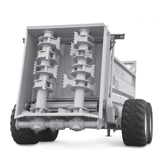
Overview TO THE NEW OPERATOR OR OWNER PRINCIPLES OF OPERATION The Degelman M28 & M34 Manure Spreaders The Manure Spreader consists of a smooth walled are designed to efficiently and uniformly spread material trailer with a floor chain drag system that manure in widths of up to 60 feet in fields. -
Page 6: Safety
Safety Why is SAFETY important to YOU? 3 BIG Reasons: •Accidents Can Disable and Kill •Accidents Are Costly •Accidents Can Be Avoided SAFETY ALERT SYMBOL The Safety Alert Symbol means: he Safety Alert Symbol identifies important safety messages applied to the Manure Spreader and in ATTENTION! this manual. - Page 7 GENERAL SAFETY YOU are responsible for the safe operation and 1. Read and understand the Operator’s maintenance of your Degelman Manure Spreader. Manual and all safety signs before YOU must ensure that you and anyone else who operating, maintaining or adjusting is going to operate, maintain or work around the Manure Spreader.
-
Page 8: Preparation
Preparation HOOK-UP / UNHOOKING The Manure Spreader should always be parked on 10. Connect the Electrical Light plug. a level, dry area that is free of debris and foreign 11. Connect the hydraulics. To connect, proceed as objects. Follow this procedure when attaching: follows: 1. -
Page 9: Tractor & Spreader Preparation
Preparation TRACTOR PREPARATION SPREADER PREPARATION Although there are no operational restrictions on the Follow this procedure when selecting and preparing Manure Spreader when it is new, there are some a tractor for use with the machine: mechanical checks that must be done to ensure the long term integrity of the unit. -
Page 10: Operation
Operation OPERATING SAFETY PRE-OPERATION CHECKLIST It is important for both personal safety and 1. Read and understand the Operator’s Manual maintaining the good mechanical condition of and all safety signs before using. the machine that this pre-operational checklist 2. Stop tractor engine, place all controls in neutral, be followed. -
Page 11: Loading / Unloading
Operation LOADING UNLOADING CONTINUED... NOTE: Before starting the table, the operator : When p IMPORTANT arking the spreader for should get the beaters up to speed and fully loading, put the tractor in PARK or NEUTRAL and open the rear gate. This prevents the spreader apply the parking brake. -
Page 12: Optional Material Trailer Use
Operation OPTIONAL MATERIAL TRAILER USAGE WARNING Stop tractor engine, place all controls in neutral, set park brake, remove ignition key and This manure spreader may also be used as a wait for all moving parts to stop before servicing, material trailer by removing the rear beater/frame cleaning, adjusting, repairing or unplugging. -
Page 13: Transporting & Storage
Transporting & Storage TRANSPORT SAFETY STORAGE SAFETY • Read and understand ALL the information in the • Store unit in an area away from human activity. Operator’s Manual regarding procedures and • Do not permit children to play around the SAFETY when operating the spreader in the stored unit. -
Page 14: Service & Maintenance
Service & Maintenance MAINTENANCE SAFETY HYDRAULIC SAFETY • Review the Operator’s Manual and all safety 1. Always place all tractor hydraulic controls in neutral items before working with, maintaining or before dismounting. operating the Manure Spreader. 2. Make sure that all components in the hydraulic •... - Page 15 Service & Maintenance TIRE SAFETY TORQUE SPECIFICATIONS 1. Failure to follow proper procedures when mounting CHECKING BOLT TORQUE a tire on a wheel or rim can produce a blow out which may result in serious injury or death. The tables shown below give correct torque values for various bolts and capscrews.
-
Page 16: Service Intervals
Service & Maintenance LUBE AFTER EVERY 8 HRS. SERVICE INTERVALS Initial & after every 8 Hrs. CAUTION Machine may be shown with check for hydraulic fluid leaks guard(s) opened for illustrative purposes only. and damaged hoses Close all guards before using. check tire pressure (65 psi) / (58 psi) Optional Tires... -
Page 17: Adjustments
1. Remove and inspect pin 142383 Decal, Caution - 1-6 Point Safety bolts and lock nuts. Lock Nut 143204 Decal, Degelman - 11” x 48-3/16" 2. Remove pin and inspect for 143288 Decal, M28 damage and/or excessive 143277 Decal, M34 wear. - Page 18 Service & Maintenance DRAG CHAIN REPLACING A DRAG CHAIN SLAT 1. Occasionally check the Drag Chain for any bent or damaged slats. It is important to straighten or replace any damaged slats immediately. Front 2. The drag chain tension should be checked and Conveyor adjusted on occasion.
-
Page 19: Repair
5. Remove seals and inspect all parts for damage. end cap to align ports. 6. Install new seals and replace damaged parts with 6. Tighten lock ring against end cap using a punch new components. and hammer. COMMON DEGELMAN CYLINDER COMPONENTS Piston Barrel Lock Nut Lock Ring O-ring... - Page 20 Service & Maintenance WHEEL HUB REPAIR IMPORTANT Be sure to block up unit securely before removing tires. COMMON SPINDLE AND HUB COMPONENTS DISASSEMBLY 1. Carefully pry off dust cap. 2. Remove cotter pin from nut. 3. Remove nut and washer. 4.
- Page 21 Service & Maintenance SPHERICAL BEARING INSTALLATION SPHERICAL BEARING COMPONENTS 117195 - Bearing Housing, c/w Retaining Rings 117196 - Bearing 117197 - Bearing Adapter Sleeve, c/w Lock Nut and Lock Washer 117198 Retaining Ring Adapter Sleeve. Lock Nut Lock Washer Snap Ring Bearing Snap Ring (Note: Do NOT grease spherical bearings)
-
Page 22: Troubleshooting
Troubleshooting TROUBLESHOOTING In the following section, we have listed some of the problems, causes and solutions that you may encounter. If you encounter a problem that is difficult to solve, even after having read through this troubleshooting section, please call your local dealer or distributor. Before you call, have this manual and the serial number from your unit ready. - Page 23 142657 - Manure Spreader (17-March-2016) -21-...
-
Page 24: Parts Section - Table Of Contents
Parts Section IMPORTANT: TABLE OF CONTENTS - PARTS SECTION Overview Frame Components READ MANUAL Walking Axle & Wheel Components Hitch Pole Components Rear Gate Components 26-27 Front Shield Components Chain & Tightener Components Rear Axle & Gearbox Components Rear Beater Gearbox Components Rear Frame &... - Page 25 Frame Components FRAME COMPONENTS New Models - Plastic Floor Strips 246894 - Floor Strip, Box - M28 (3) 246895 - Floor Strip, Box - M34 (3) 249031 - Main Frame Assembly, M28 (1) 502026 - Bushing (2) 249041 - Main Frame Assembly,...
- Page 26 Walking Axle & Wheel Components WALKING AXLE COMPONENTS - STANDARD 246391 - Threaded rod Assembly (1) 246735 - Plug Assembly (1) 246725 - Walking Wheel Assembly (2) 246734 - Disc, Wear-Nylon (2) 131206 - Flat Washer, 1-1/4 (1) 118445 - Lock nut, 1-1/4 (1) 246735 - Plug Assembly (1) WHEEL COMPONENTS - STANDARD...
- Page 27 Walking Axle & Wheel Components HUB/SPINDLE COMPONENTS 131396 - Hub/Spindle Assembly (4) comes with... 118158 - Bolt, 131397 - Spindle, S1020 (2) 3/4 x 7 (2) 118422 - Lock Nut, 3/4 (2) 131358 - Hub (1) comes with Bearing Cups 131359 - Bearing, Cup - Inner (1) 131363 - Dust Seal, CR43771 (1) 131360 - Bearing, Cup - Outer (1)
- Page 28 Hitch Pole Components 246503 - Pin, Hitch Pole (2) 118050 - Bolt, 3/4”x 3” (1) HITCH POLE COMPONENTS 118845 - Roll Pin, 5/16” 118775 - Flat Washer, 246700 - Hitch Pole Assy (1) x 2-1/2” (2) 3/4” SAE (1) 240286 - Bushing, Mach 246507 - Bushing, 1-1/2”...
- Page 29 Rear Gate Components REAR GATE COMPONENTS 788601 - Pin, 1-1/4 x 3-5/8 (1) 810280 - Retaining Ring, 1-1/4 (2) 141518 - 90° Elbow, 3/4 JIC-m x 3/4 JIC-f-sw (1) 141501 - Tee, 3/4 JIC-m x m x m (1) 141583 - Adaptor, 3/4 JIC-f-sw x 9/16 ORB (1) 246375 - Rear Gate Assembly (1) (comes with lower flap assembly) 788601 - Pin, 1-1/4 x 3-5/8 (1)
- Page 30 Front Shield Components 246409 - Front Shield, Assembly (1) FRONT SHIELD COMPONENTS comes with handle and latches... 133092 - Handle (1) 133094 - Nut, M8 x 1.25 (2) 133093 - Capscrew, SH M8 x 1.25 x 30mm (2) 118998 - Mach Screw, #10-24 x 1/2”(4) 118999 - Lock Washer, #10 (4) 118000 - Nut, #10-24 UNC (4)
- Page 31 3/8 x 1-1/2 (2) 118703 - Lock Nut, 5/16 (1) CHAIN ASSEMBLY COMPONENTS 246415 - Chain Assembly - 24 Slat Holder (2) - M28 246425 - Conveyor Slat (24) M28 Model 246541 - Chain Assembly - 28 Slat Holder (2) - M34...
- Page 32 Rear Axle & Gearbox Components REAR DRIVE AXLE COMPONENTS 810282 - Retaining Ring, Ext 2-3/4 (1) 246429 - Gearbox/Hyd. Motor Assembly (1) 118011 - Bolt, 1/2 x 1-1/2 (12) 118504 - Lock Washer, 1/2 (12) 118405 - Nut, 1/2 (12) 246649 - Conveyor Drive Axle (1) 246802 - Holder Assembly,...
- Page 33 Rear Beater Gearbox Components GEARBOX COMPONENTS 170460 - Ring, Threaded (1) 170454 - Washer, Notched (2) 170447 - Complete Gearbox Assembly (1) 170455 - Gear, Pinion - 13 teeth (2) 170485 - Output Hub 170456 - Bearing, Assembly, Complete (2) 32212 (2) (See Detail Below) 170459 - Ring, Retaining -...
- Page 34 Rear Frame & Beater Components REAR BEATER FRAME ASSEMBLY 246617 - Frame, Beater LH Side (1) 246616 - Frame, Beater RH Side (1) Top & Bottom 118024 - Bolt, 5/8 x 1-1/2 (1) 118508 - Lock Washer, 5/8 (1) WARNING When installing/replacing 118407 - Nut, 5/8 (1) complete beater assembly, ensure bottom plate...
- Page 35 Rear Frame & Beater Components TOP BEATER FRAME & BEARINGS 246620 - Shield, Top 118302 - Capscrew, Self-Tap - 3/8 x 1 (4) Beater Bearing (1) 117215 - Bearing Unit, Assembly (2) comes with... IMPORTANT: After nut is properly tightened, bend tab(s) of lock ring 118703 - Lock Nut, 5/16 (3) onto nut.
- Page 36 Rear Frame & Beater Components BEATER CORE & PIN ASSEMBLY Note: Previous paddle design used a 5-1/8” 246628 - Pin, 2 x 7-3/4 (15) bushing and single-lip seals: 118027 - Bolt, 5/8 x 2 (30) 246279 - Seal, Wiper - Single Lip (2) 118447 - Lock Nut, 5/8 (30) Updated design uses a slightly shorter 5”...
- Page 37 118514 - Flat Washer, 5/8 (2) 118009 - Bolt, 1/2 x 1-1/4 (4) 118508 - Lock Washer, 5/8 (2) M28 - Qty (2) / M34 - Qty (3) 118407 - Nut, 5/8 (2) 117220 - Bearing Assembly (1) 246738 - Bracket,...
- Page 38 Driveline Components 160352 - DRIVELINE SLIDER SHAFT, 37-48 - (Standard on models produced after June 2011) 160328 - Cut-out Clutch (1) 160312 - Cross & Bearing, Kit (1) 160327 - Overrunning Clutch & S4 (1) 160361 - Guard Kit, Complete (1) Note: CV is typically shipped without grease.
- Page 39 Driveline Components 160374 - DRIVELINE SLIDER SHAFT, 36-49 - (Optional) 160380 - Cut-out Clutch (1) 160376 - Cross & Bearing, Kit (1) 160379 - Yoke Inboard S5 (1) 160378 - Spring Pin (1) 160384 - Guard Kit, Complete (1) 160378 - Spring Pin (1) 160377 - Yoke Inboard S5 (1) 160375 - Overrunning Clutch (1) 160310 - DRIVELINE SLIDER SHAFT...
- Page 40 Mounting Hardware (as required) 249112 - Hose Shield, - Front M28 (1) 246512 - Hose Shield, M28 (1) 249111 - Hose Shield, - Rear M28 (1) 118026 - Bolt, 5/8 x 2 118508 - Lock Washer, 5/8 118514 - Flat...
- Page 41 122570 - Cylinder, 2” x 72” 126654- Hose, 3/8 x 510 (2) x 1-1/4” (2) 126619- Hose, 3/8 x 466 (2) Hoses for M28 Only 126619- Hose, 3/8 x 466 (2) 126663- Hose, 3/8 x 420 (2) Hoses for both Models...
- Page 42 Electrical Components - Lights LIGHT ROUTING & COMPONENTS Note: Wire runs through top tube to LH Light. LH Light Wire Harness for Lights RH Light Wire Harness with Plug Note: Attach electrical wiring to hydraulic lines with plastic tie straps. Module 246528 - Clearance Lights Wiring Harness Kit (1) 246526 - Light Enhancing Module (1)
- Page 43 Electrical Components - Flow Control Valve Electrical Control Box Note: Install control box inside of tractor and Note: Attach connect tractor cable electrical wiring to connector. hydraulic lines with plastic tie straps. Tractor Cable 246808 - Hose Wrap, Spiral (2) Connection Note: Wrap hydraulic hoses in pairs with hose wrap (2), include electrical cable.
-
Page 44: Warranty
Re-torque of fastening hardware, Hydraulic fluid purities, drive train alignments, and clutch operation) 3. If parts not made or supplied by Degelman have been used in the connection with the unit, if, in the sole judgement of Degelman such use affects its performance, safety, stability or reliability. -
Page 45: B O X
It is the retail customer’s responsibility to deliver the product to the authorized Degelman dealer, from whom he purchased it, for service or replacement of defective parts, which are covered by warranty. Repairs to be submitted for warranty consideration must be made within forty-five days of failure.
Need help?
Do you have a question about the M28 and is the answer not in the manual?
Questions and answers