Table of Contents
Advertisement
Quick Links
D E G E L M A N
I N D U S T R I E S
B O X
8 3 0 - 2 7 2
I N D U S T R I A L
R E G I N A ,
S K ,
C A N A D A ,
F A X 3 0 6 . 5 4 3 . 2 1 4 0
P H 3 0 6 . 5 4 3 . 4 4 4 7
1 . 8 0 0 . 6 6 7 . 3 5 4 5
D E G E L M A N . C O M
L P
D R I V E ,
S 4 P
3 B 1
OPERATOR & PARTS
MANUAL
143436 v1.0
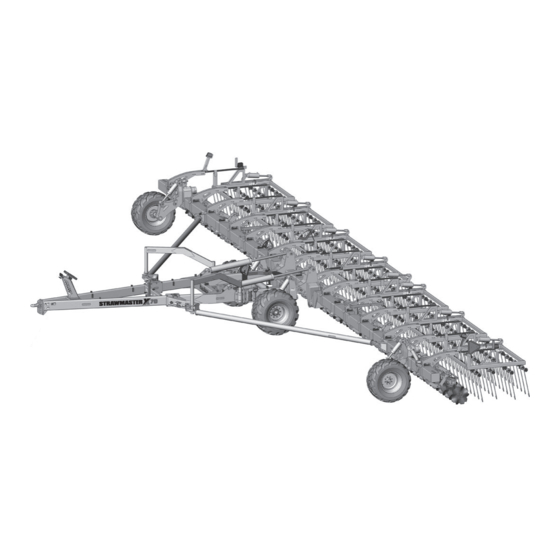
STRAWMASTER X
70
Advertisement
Table of Contents

Subscribe to Our Youtube Channel
Related Manuals for Degelman STRAWMASTER X 70


Summary of Contents for Degelman STRAWMASTER X 70
- Page 1 OPERATOR & PARTS MANUAL 143436 v1.0 STRAWMASTER X D E G E L M A N I N D U S T R I E S B O X 8 3 0 - 2 7 2 I N D U S T R I A L D R I V E , R E G I N A , S K ,...
- Page 3 QUICK-START GUIDE WARRANTY STRAWMASTER REMEMBER! You must complete Product * Refer to operators manual for complete safety and operation info. Registration to be eligible for Warranty. WHEELS......Wheel Height Cylinders Connect Hydraulics TRANSPORT..... Transport Cylinders DISCS........ Disc Cylinders TINE ANGLE..... Harrow Section Cylinders LATCH &...
- Page 4 5) Install all frame transport pins (2), cylinder lock bars (2), and endwheel transport bars (2). IMPORTANT: Endwheel transport bars MUST be installed during transport. 6) Ensure SMV sign and re ectors are clean and lights are working. Follow all local transport laws when transporting. © 2022 Degelman Industries LP...
-
Page 5: Table Of Contents
* Reference Sheet Quick-Start Guide OPERATORS SECTION - TABLE OF CONTENTS Introduction Safety Operation Pre-Operation Checklist Hook-Up Transport to Field Position Indicator Overview Settings & Adjustments Service & Maintenance Maintenance Checklist & Specifications Repair - Hydraulic Cylinder Repair Maintenance Free Pins & Bushings Repair - Pressed Bushing IMPORTANT: INSTALL DRY Repair - Wheel Hub... -
Page 7: Introduction
Use this manual as your first source of information about this machine. TO THE NEW OPERATOR OR OWNER - Safe, efficient and trouble free operation of your Degelman Strawmaster X requires that you and anyone else who will be operating or maintaining it, read and understand the Safety, Operation, Maintenance and Troubleshooting information contained within this manual. -
Page 8: Safety
Safety Why is SAFETY important to YOU? 3 BIG Reasons: •Accidents Can Disable and Kill •Accidents Are Costly •Accidents Can Be Avoided SAFETY ALERT SYMBOL The Safety Alert Symbol means: he Safety Alert Symbol identifies important safety messages applied to the Strawmaster and in this ATTENTION! manual. - Page 9 Safety SAFETY GENERAL SAFETY YOU are responsible for the safe operation and 1. Read and understand the Operator’s maintenance of your equipment. Manual and all safety signs before operating, maintaining or adjusting. YOU must ensure that you and anyone else who is going to operate, maintain or work around 2.
-
Page 10: Operation
Operation TO THE NEW OPERATOR OR OWNER BRIEF OVERVIEW OF OPERATION The Degelman Strawmaster X is designed for • Operating speed will depend on tractor sizing residue while leaving standing material horsepower, environmental conditions and each and allows for more tillage than a heavy harrow particular operation. -
Page 11: Pre-Operation Checklist
Operation BREAK-IN PRE-OPERATION CHECKLIST Although there are no operational restrictions on It is important for both personal safety and the Strawmaster X when it is new, there are some maintaining the good mechanical condition of mechanical checks that must be done to ensure the machine that this pre-operational checklist be the long term integrity of the unit. -
Page 12: Hook-Up
Operation TRANSPORT SAFETY HOOK-UP / UNHOOKING The Strawmaster X should always be parked on 1. Check with local authorities regarding machine a level, dry area that is free of debris and foreign transport on public roads. Obey all applicable objects. Follow this procedure to hook-up: laws and regulations. -
Page 13: Transport To Field Position
Operation TRANSPORT TO FIELD POSITION 9 9 ) Note: Ensure there is plenty of room behind and to the sides of the Strawmaster before backing into field position. 7) 7) 8) 8) 1) 1) ENSURE jacks are raised prior to backing up. 6 6 ) 2) 2) REMOVE transport pins/bars and store. -
Page 14: Indicator Overview
Operation - Indicator Overview Tine Angle Indicator The Tine Angle Indicator is an overall visual indicator of the current setting the harrow section tine angles are set at. This indicator will adjust in real-time as you activate the hydraulics from the tractor. Disc Height Indicator Provides a visual indication of the current disc height setting. -
Page 15: Settings & Adjustments
Operation - Tine Angle Settings TINE ANGLE ADJUSTMENT TRAILER & WING BEAM HEIGHT ADJUSTMENT Strawmaster X has Hydraulic Tine Adjustment. After Tine Angle Adjustment is complete, adjust wheel Tine angle adjustment should be made with the height until the cart/trailer frame is parallel to the machine in field position. - Page 16 Operation - Disc Angle Settings DISC ANGLE INDICATOR DISC OPTIONS The disc angle is Wave Samurai indicated by the • Good for cutting heavy trash and edge of the disc mixing soil while incorporating. frame bar in relation • Extremely aggressive edge maintains to the numbers penetration and wear.
- Page 17 Operation - Adjustments: Rephasing Cylinders Overview & Principles of Rephasing Troubleshooting A Rephasing Cylinder System enables a pair (or Series rephasing cylinder systems (Master and multiple) cylinders to extend and retract in very near Slave(s)) can exhibit undesirable behaviors such as unison.
-
Page 18: Service & Maintenance
Service & Maintenance MAINTENANCE SAFETY MAINTENANCE CHECKLIST • Review the Operator’s Manual and all safety items After reviewing the Maintenance and Hydraulic before working with, maintaining or operating the Safety Information, use the Maintenance Checklist Strawmaster provided for regular service intervals and keep a record of all scheduled maintenance: •... - Page 19 Service & Maintenance HARDWARE SPECIFICATIONS HYDRAULIC SAFETY Note: Unless stated otherwise, hardware is typically: • Make sure that all components in the hydraulic Hex, Plated GR5 UNC or P8.8 (metric) system are kept in good condition and are clean. • Replace any worn, cut, abraded, fl attened or TORQUE SPECIFICATIONS crimped hoses and metal lines.
- Page 20 Service & Maintenance HYDRAULIC FITTING INSTALLATION Note: A DASH size refers to a diameter of a hose (inside) or of a tube (outside) measured in 1/16” increments. The following info is to help you identify and properly For example, a Hose specifi ed as dash 8 or -8 would install some of our standard hydraulic fi...
- Page 21 Service & Maintenance HYDRAULIC CYLINDER REPAIR REPAIRING A THREADED HEAD CYLINDER PREPARATION Set Screw Style When cylinder repair is required, clean off unit, Barrel Set Screw disconnect hoses and plug ports before removing Gland cylinder. When removed, open the cylinder ports and drain the cylinder's hydraulic fl...
- Page 22 Service & Maintenance REPLACING A PRESSED BUSHING NOTE: You may need the following tools: Press, hammer, punch, pry-bar, "Step-Tool" Use the following as a guideline for repair: 1. Ensure the area and frame are properly secured, supported, and safe to work on. Safely remove the pin(s), cylinder, and/or components necessary in order to access and work on the damaged bushing.
- Page 23 Service & Maintenance WHEEL HUB REPAIR WHEEL NUT & WHEEL BOLT TORQUE TORQUE BOLT PATTERNS IMPORTANT Be sure DISASSEMBLY to block up unit securely before removing tires. 1. Remove dust cap. COMMON 2. Remove cotter pin from nut. HUB & SPINDLE 5 BOLT PATTERN 6 BOLT PATTERN 8 BOLT PATTERN...
- Page 24 Service & Maintenance - Tine Replacement TINE REPLACEMENT Note: Tines must be replaced when worn down DISASSEMBLY: to 20 in. or less in length. Tines may be replaced Follow this procedure one pipe row at a time so while the machine is in transport position, or field pipes do not get mixed up, or number each pipe position.
-
Page 25: Troubleshooting
Troubleshooting GENERAL TROUBLESHOOTING In the following section, we have listed some of the problems, causes, and solutions that you may encounter. If you encounter a problem that is difficult to solve, even after having read through this troubleshooting section, please call your local dealer or distributor. Before you call, have this manual and the serial number from your unit ready. - Page 26 142755 - Decal, Field/Transport (2) 143162 - Decal, Read Manual (1) 142710 - Decal, 142008 - Decal, 142753 - Hoses Label (1) Degelman (1) Warning Decal, 251010 - Trailer Hitch Pinch Point (2) Frame Assembly (1) 142711 - SMX 132030 - Jack,...
-
Page 27: Front Trailer Components
Front Trailer Components Exploded Latch Components (LH exploded assembly shown) 117397 - Bolt, 3/4 x 7 GR8 (12) 118775 - Flat Washer, 3/4 F436 (24) 117414 - Lock 575194 - Pin Head (2) Nut, 3/4 GRC 249958 - Pin Shaft, 2 x 7-1/2 (2) 251132 - Mount Plate (2) Unitorque (12) 117426 - Bolt, 7/8 x 2-3/4 GR8 (2) - Page 28 Hydraulic Jack Components Hydraulic Jack Components 251160 - Hyd Park 118048 - Bolt, 3/4 x 2-1/2 GR8 (4) Jack Mount (1) 118775 - Flat Washer, 3/4 F436 (8) 117414 - Lock Nut, 3/4 GRC Unitorque (4) 251166 - Clamp Plate (1) 249969 - Pin Shaft, 1-1/2 x 10-3/4 (2) 142650 - Decal, Fluorescent...
-
Page 29: Rockshaft Components
Rock Shaft Components Rock Shaft Components 123089 - Cylinder, Cast Bearing Assembly IMPORTANT: Torque to 117225 - Bushing, 2-1/2 OD x 2 (4) Monarch - 4-3/4 550 lb . ft (750 N . m) Components (2) 133135 - Wiper Seal, 2-1/2 OD (4) x 8 x 2 (2) (Seal Kit: 123224) 118178 - Bolt, 1... -
Page 30: Center & Wing Beam Components
Center & Wing Beam Components Center Beam Components 251050 - Center Beam Assembly (1) 117416 - Lock Nut, 7/8 Unitorq (2) 118774 - Flat washer, 7/8 - F436 (4) 118767 - Bolt, 7/8 x 3 GR8 (2) 575198 - Pin Head (2) 575197 - Pin Shaft, 2 x 12-1/4 (2) 117462 - Flat Washer, 5/8 (2) -
Page 31: End Wheel Components
End Wheel Assembly End Wheel Overview (LH Shown - RH is Mirrored) 118113 - Bolt, 123756 - Cylinder, Monarch 1 x 9 (2) 142714 - Important, Decal, Cyl Bar (2) - 3-1/2 x 16 x 1-1/2 (2) (Seal Kit: 123653) 249348 - 142753 - Warning Decal, Pinch Point (2) Collar (2) -
Page 32: Wing/Center Beam Mount Locations
Wing/Center Beam Mount Locations SMX Top Overview (Location overview for Disc Assembly and Harrow Section mounting) - Disk Arm Linkage Assembly 1 or 2 - Disk Arm Linkage Assembly 1 or 2 DL # DL # - Disk Assembly - Disk Assembly A, B, C, D or E A, B, C, D or E HS-C HS-C... - Page 33 Wing/Center Beam Mount Locations Center Section Mounting Location Overview Install Disc Assembly Install Disc Assembly (DA-C) and Disc Link- (DA-C) and Disc Link- age (DL #3) centered age (DL #3) centered on the center beam. on the center beam. 28-3/4" 28-3/4"...
-
Page 34: Harrow Section Components
Harrow Section Components Harrow Spring Bar Assembly Components (2 per Harrow Section) (Center Section 251226 - Bungie Bracket (2) Only) 118056 - Bolt, 3/4 x 4 GR8 (1) 133149 - Bungie, Spring (2) 133150 - Tie Cable (2) 243061 - Bar, 118775 - Flat Washer, 3/4 F436 (4) Back-up (1) 118094 - Bolt, 5/8 x 4 GR8 (2) -
Page 35: Wing Section Components
Wing Section Components Indicator Assembly Components RH WING - 1st Harrow Section Center Harrow Section 117866 - Rivet, 251233 - Tine Angle Blind - 3/16 (4) Indicator, Scale Plate (1) 251230 - Tine Angle Indicator Assembly (1) 251234 - 118447 - Tine Angle No Tine Stops Lock Nut, 5/8... -
Page 36: Disc Section Assemblies & Components
Disc Arm Linkage Components DL #1 - Disc Arm Linkage Assembly #3 Components DL #1 DL #1 Cylinder Down Linkage Assembly DL #1 DL #1 251245 - V-Clamp Assembly (1) 251670 - Cylinder Link Holder Assembly, Down (1) 251675 - Cylinder Link Arm 118048 - Bolt, 3/4 Assembly, Down (1) x 2-1/2 GR8 (4) - Page 37 Disc Assembly - Center Center Disc Section Component Overview DA-C DA-C (Center Section) 251700 - Pivot Tube Assembly, Cylinder-Down (1) RH Turnbuckle Configuration LH Turnbuckle Configuration Spring Bar/Bolt Plate LH Configuration (3) Offset Disc Holders - Installed on Spring Bar/Bolt Plate middle two center section spring RH Configuration (3) bars only, refer to detail on "Disk...
- Page 38 Disc Assembly - LH LH Disc Section Component Overview DA-A DA-A (LH Wing Outer and Third Section) 251705 - Pivot Tube Assembly, Cylinder-Up (1) LH Turnbuckle Configuration Spring Bar/Bolt Plate LH Configuration (6) LH Disc Section Component Overview DA-B DA-B (LH Wing Second Section) 251700 - Pivot Tube Assembly,...
- Page 39 Disc Assembly - RH RH Disc Section Component Overview DA-D DA-D (RH Wing Outer and Third Section) 251705 - Pivot Tube Assembly, Cylinder-Up (1) RH Turnbuckle Configuration Spring Bar/Bolt Plate RH Configuration (6) RH Disc Section Component Overview DA-E DA-E (RH Wing Second Section) 251700 - Pivot Tube Assembly,...
- Page 40 Disc Mounting Components Spring Bar/Bolt Plate Components (Quantities shown are numbers required for each Spring Bar) 117639 - Bolt, 117461 - Bolt, 5/8 117461 - Bolt, 5/8 5/8 x 5-1/2 x 6 GR8 (0 or 2) x 6 GR8 (0 or 2) GR8 (3 or 1) (Only if Turnbuckle (Only if Turnbuckle...
- Page 41 Disc Options Disc Option Component Overview Wave Samurai 251990 - Samurai, Wave Set (84) • Good for cutting heavy trash and 143499 - Samurai, Wave - 20" (1) mixing soil while incorporating. • Extremely aggressive edge maintains penetration and wear. •...
- Page 42 Hydraulic Layout - Wheels 141581 - Coupler Tip, 3/4 ORB-F (2) Hydraulic Fittings Required 141581 - Coupler Tip, 3/4 ORB F 141676 - Connector, 141676 - Connector, 3/4 ORB M x M 3/4 ORB M x M (2) 141684 - Coupler, Green (+) 141685 - Coupler, –...
-
Page 43: Hydraulic Routing - Transport
Hydraulic Layout - Transport Hydraulic Fittings Required 141581 - Coupler Tip, 141581 - Coupler Tip, 3/4 ORB F 3/4 ORB-F (2) 141676 - Connector, 3/4 ORB M x M 141676 - Connector, 141682 - Coupler, Blue (+) 3/4 ORB M x M (2) 141683 - Coupler, Blue (-) 141682- Coupler, 141703 - Adaptor, 1/2 ORB M x ORFS M... -
Page 44: Hydraulic Routing - Doc
Hydraulic Layout - DOC Hydraulic Fittings Required 141581 - Coupler Tip, 141581 - Coupler Tip, 3/4 ORB F 3/4 ORB-F (2) 141676 - Connector, 3/4 ORB M x M 141676 - Connector, 141686 - Coupler, Brown (+) 3/4 ORB M x M (2) 141687 - Coupler, Brown (-) 141686 - Coupler, 141703 - Adaptor, 1/2 ORB M x ORFS M... -
Page 45: Hydraulic Routing - Tine Angle
Hydraulic Layout - Tine Angle Hydraulic Fittings Required 141581 - Coupler Tip, 141581 - Coupler Tip, 3/4 ORB F 3/4 ORB-F (2) 141676 - Connector, 3/4 ORB M x M 141676 - Connector, 141688 - Coupler, Black (+) 3/4 ORB M x M (2) 141689 - Coupler, Black (-) 141689 - Coupler, –... -
Page 46: Hydraulic Routing - Latch & End Wheel
Hydraulic Layout - Latch & Endwheel Steering 141581 - Coupler Tip, 3/4 ORB-F (2) Hydraulic Fittings Required 141581 - Coupler Tip, 3/4 ORB F 141676 - Connector, 141676 - Connector, 3/4 ORB M x M 3/4 ORB M x M (2) 141680 - Coupler, Grey (+) 141681 - Coupler, –... -
Page 47: Hydraulic Routing - Jack
Hydraulic Layout - Hydraulic Jack Hydraulic Fittings Required 141581 - Coupler Tip, 141581 - Coupler Tip, 3/4 ORB F 3/4 ORB-F (2) 141676 - Connector, 3/4 ORB M x M 141676 - Connector, 141759 - Coupler, Purple (-) 3/4 ORB M x M (3) 141758 - Coupler, Purple (+) 141758- Coupler, 141703 - Adaptor, 1/2 ORB M x ORFS M... -
Page 48: Electrical Layout & Light Components
Electrical Layout / Light Components Wire Harness - w/plugs (1) 251375 - SMX 70 Follow Hose Routing & attach with Zip Ties 129127 - Lamp, Single Amber (2) (2 Pin) 129129 - Lamp, Single Red (2) (3 Pin) -42- 143436 - STRAWMASTER X (28-January-2022) -
Page 49: Warranty
Re-torque of fastening hardware, Hydraulic fluid purities, drive train alignments, and clutch operation) 3. If parts not made or supplied by Degelman have been used in the connection with the unit, if, in the sole judgement of Degelman such use affects its performance, safety, stability or reliability. -
Page 50: B O X
It is the retail customer’s responsibility to deliver the product to the authorized Degelman dealer, from whom he purchased it, for service or replacement of defective parts, which are covered by warranty. Repairs to be submitted for warranty consideration must be made within forty-five days of failure.
Need help?
Do you have a question about the STRAWMASTER X 70 and is the answer not in the manual?
Questions and answers