Table of Contents
Advertisement
D E G E L M A N
I N D U S T R I E S
B O X
8 3 0 - 2 7 2
I N D U S T R I A L
R E G I N A ,
S K ,
C A N A D A ,
F A X 3 0 6 . 5 4 3 . 2 1 4 0
P H 3 0 6 . 5 4 3 . 4 4 4 7
1 . 8 0 0 . 6 6 7 . 3 5 4 5
D E G E L M A N . C O M
L T D.
D R I V E ,
S 4 P
3 B 1
OPERATOR & PARTS
MANUAL
142922 v1.7
SIGNATURE SERIES
6000/7200
ROCK PICKERS
Advertisement
Table of Contents

Related Manuals for Degelman Signature Series


Summary of Contents for Degelman Signature Series
- Page 1 OPERATOR & PARTS MANUAL 142922 v1.7 SIGNATURE SERIES D E G E L M A N I N D U S T R I E S L T D. B O X 8 3 0 - 2 7 2 I N D U S T R I A L...
-
Page 3: Table Of Contents
TABLE OF CONTENTS - OPERATORS SECTION Introduction Safety Overview Preparation Pre-Operation Checklist Tractor Preparation Hook-up / Unhooking Rock Picker Preparation Operation Transporting Troubleshooting Service & Maintenance Service Intervals Adjustments 20-21 Repair 22-27 Storage / Safety Decals TABLE OF CONTENTS - PARTS SECTION Warranty IMPORTANT: D E G E L M A N... -
Page 5: Introduction
If you follow the instructions given in this manual, your machine will work well for many years. Safe, efficient and trouble free operation of your Degelman Rock Picker requires that you and anyone else who will be operating or maintaining the Picker, read and understand the Safety, Operation, Maintenance and Troubleshooting information contained within this Manual. -
Page 6: Safety
Safety Why is SAFETY important to YOU? 3 BIG Reasons: •Accidents Can Disable and Kill •Accidents Are Costly •Accidents Can Be Avoided SAFETY ALERT SYMBOL The Safety Alert Symbol means: he Safety Alert Symbol identifies important safety messages applied to the Rock Picker and in this ATTENTION! manual. - Page 7 GENERAL SAFETY YOU are responsible for the safe operation and 1. Read and understand the Operator’s maintenance of your Degelman Rock Picker. YOU Manual and all safety signs before must ensure that you and anyone else who is going operating, maintaining or adjusting to operate, maintain or work around the Rock Picker the Rock Picker.
-
Page 8: Overview
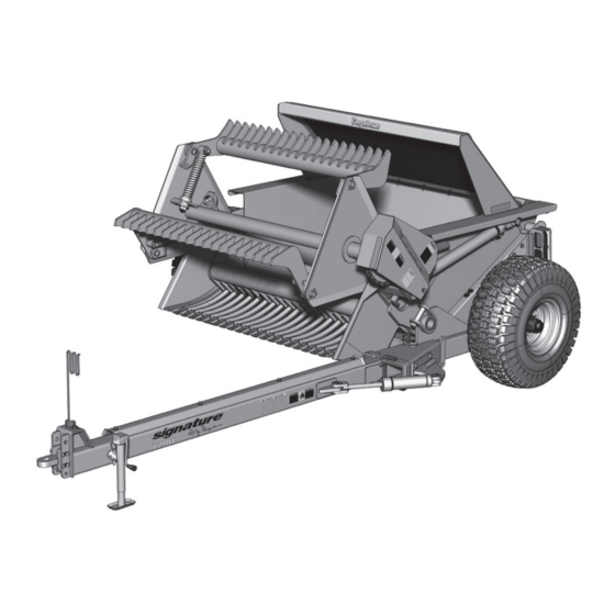
Overview 6000 HYDRAULIC DRIVE (standard long pole) 7200 HYDRAULIC DRIVE (standard long pole) 6000 HYDRAULIC DRIVE (short pole option) 7200 HYDRAULIC DRIVE (short pole option) 6000 PTO DRIVE (short pole only) 7200 PTO DRIVE (short pole only) 142922 - Signature 6000/7200 (16-August-2017) - Page 9 Overview TO THE NEW OPERATOR OR OWNER PRINCIPLES OF OPERATION The Degelman Signature Series Rock Pickers are The Rock Picker is a framework of steel bars called a designed to efficiently gather rocks from 1-3/4 to grille that moves along the surface of the ground to 24 inches (45 to 600mm) diameter and debris gather rocks and debris.
-
Page 10: Preparation
Preparation BREAK-IN OPERATING SAFETY Although there are no operational restrictions on 1. Read and understand the Operator’s Manual the Rock Picker when it is new, there are some and all safety signs before using. mechanical checks that must be done to ensure the long term integrity of the unit. -
Page 11: Pre-Operation Checklist
Preparation PRE-OPERATION CHECKLIST TRACTOR PREPARATION It is important for both personal safety and Follow this procedure when selecting and preparing maintaining the good mechanical condition of a tractor for use with the machine: the machine that this pre-operational checklist be followed. 1. -
Page 12: Hook-Up / Unhooking
Preparation HOOK-UP / UNHOOKING 8. Connect the hydraulics. To connect, proceed as The Rock Picker should always be parked on a level, follows: dry area that is free of debris and foreign objects. Follow this procedure when attaching: • Use a clean cloth or paper towel to clean the couplers on the ends of the hoses. - Page 13 Preparation DRIVELINE HEIGHT (PTO Drive Models) The clearance between the PTO driveline and the top of the hitch clevis should be at least 4 inches to provide adequate clearance when going over the crest of a hill. To adjust this clearance, follow this procedure: 1.
-
Page 14: Rock Picker Preparation
Preparation ROCK PICKER PREPARATION 1. Hitch Pole “Field/Transport” configuration: The hitch pole has a “transport” position that is normally used when the machine is new or when it will be transported for long distances to bring the body of the machine as close behind the tractor as possible. -
Page 15: Operation
Operation OPERATING 4. Ground Speed: Refer to these operational hints before starting: Operating speed will vary 1. Material size: according to: 1-3/4” to 24” The machine was designed • rock size and density to pick and unload rock RECOMMENDED SPEED and debris ranging in size •... - Page 16 Operation 6. Reel Speed: 7. Loading/Dumping: The purpose of the reel is to sweep the rocks a. Loading: The machine can be loaded until from the front of the grille over the grille the hopper box is filled and rocks stay on the framework and into the hopper box.
- Page 17 Operation 8. Safety Area: 9. Jamming/Unplugging: Always treat the machine with the utmost WARNING Never use hands. Never get your respect when it is operating. Since the paddles head or arms into the machine. Stay clear are all loaded with strong springs, they can of the paddle when removing any lodged catch and throw rocks a considerable distance material.
-
Page 18: Transporting
Transporting TRANSPORTING TRANSPORT SAFETY Follow this procedure when preparing to transport: • Read and understand ALL the information in the Operator’s Manual regarding procedures and 1. Clear the area of bystanders, especially small SAFETY when operating the Rock Picker in the children, before converting into transport field/yard or on the road. -
Page 19: Troubleshooting
Troubleshooting TROUBLESHOOTING In the following section, we have listed some of the problems, causes and solutions that you may encounter. If you encounter a problem that is difficult to solve, even after having read through this troubleshooting section, please call your local dealer or distributor. Before you call, have this manual and the serial number from your unit ready. -
Page 20: Service & Maintenance
Service & Maintenance MAINTENANCE SAFETY FLUIDS AND LUBRICANTS • Review the Operator’s Manual and all safety 1. Grease: Use an SAE multi-purpose items before working with, maintaining or grease with extreme pressure (EP) operating the Rock Picker. performance. Also acceptable is an SAE multi-purpose lithium base grease. -
Page 21: Service Intervals
Service & Maintenance SERVICE INTERVALS Annually Nipple on Pillow Block CAUTION Machine may be shown with Bearing 8 Hrs. guard(s) opened for illustrative purposes only. Slider Close all guards before using. 8 Hrs. Shaft/ Guard Bushing Tube LUBE AFTER EVERY 8 HRS. (both ends) 8 Hrs. - Page 22 Service & Maintenance HARDWARE SPECIFICATIONS HYDRAULIC SAFETY Note: Unless stated otherwise, hardware is typically: • Make sure that all components in the hydraulic Hex, Plated GR5 UNC or P8.8 (metric) system are kept in good condition and are clean. • Replace any worn, cut, abraded, fl attened or TORQUE SPECIFICATIONS crimped hoses and metal lines.
- Page 23 Service & Maintenance HYDRAULIC FITTING INSTALLATION Note: A DASH size refers to a diameter of a hose (inside) or of a tube (outside) measured in 1/16” increments. The following info is to help you identify and properly For example, a Hose specifi ed as dash 8 or -8 would install some of our standard hydraulic fi...
-
Page 24: Adjustments
Service & Maintenance HITCH CLEVIS ADJUSTMENTS REEL DRIVE CHAIN TENSION The hitch pole should always be set to be parallel to A roller chain transmits power to the reel. Check the ground when attached to the tractor. To set this tension daily and tighten to remove excessive slack. - Page 25 Service & Maintenance PADDLE SPRING TENSION (6000 MODEL) PADDLE TEETH ALIGNMENT A spring on the paddles allows the paddles to flip back out of the way when blocked by a rock and yet return to their normal position for the next reel cycle. A small adjustment is available with the eye bolt on the end of the spring.
-
Page 26: Repair
Service & Maintenance PADDLE AND GRILLE TEETH REPAIR OR BEARING REPLACEMENT REPLACEMENT When bearing noise becomes evident, replacement of the bearing is necessary. Whether the complete bearing unit or just the bearing insert was Securely block up grille before attempting any purchased, proceed as follows: work on grille teeth. - Page 27 Service & Maintenance TIRE SAFETY WHEEL HUB REPAIR 1. Failure to follow proper procedures when mounting IMPORTANT Be sure a tire on a wheel or rim can produce a blow out DISASSEMBLY to block up unit securely which may result in serious injury or death. before removing tires.
- Page 28 Service & Maintenance HYDRAULIC CYLINDER REPAIR 5. Take the plastic removal ring from the seal kit: PREPARATION Types of Cylinders a) Straighten the ring and remove any kinks or When cylinder repair (Wire Ring / Threaded Head) excessive curl to make installation easier and is required, clean off prevent it from falling out.
- Page 29 Service & Maintenance 8. Remove locknut, piston and head from rod. 11. b) Tighten the band clamp to ensure the wire ring is fully seated. Then, loosen the clamp Piston Seal (2pcs) approx. 1/2 a turn to allow band clamp to slide Wear Ring during fi nal assembly.
- Page 30 Service & Maintenance REPAIRING A THREADED HEAD CYLINDER REPAIRING A THREADED HEAD CYLINDER Set Screw Style Locking Ring Style Barrel Barrel Set Screw Locking Gland Ring Lock Piston U-Cup Wear Dual Seal Seal Piston Ring O-Rings Seal Wiper Piston Seals Seal (Style may vary, Lock...
- Page 31 Service & Maintenance Repair And Rebuilding PTO TORQUE LIMITER/SLIP CLUTCH Disassembly Torque Limiter Run In & Repair 1. Place the clutch and universal joint assembly on a Tools Required: 1/2” or M13 box wrench or socket. bench, with the end of the clutch accessible. 2.
-
Page 32: Storage / Safety Decals
142407 Decal, Important - Chain Maintenance Remove the entangled material. 3. Lubricate all grease fittings to remove any 142010 Decal, Degelman - 2-3/4” x 12" moisture in the bearings. 142009 Decal, Degelman - 3-3/4” x 16-1/4” 4. Run the machine slowly for 1 minute to 142008 Decal, Degelman - 6”... -
Page 33: Table Of Contents - Parts Section
Parts Section TABLE OF CONTENTS - PARTS SECTION IMPORTANT: Initial Assembly Set-Up Hitch Pole Components 30-31 READ MANUAL Frame & Hopper Components Rockguard & Wheel Components Reel Components Grille Components Hydraulic Models Hydraulic Drive Components Hydraulic Drive Installation PTO Models PTO Drive Components 38-39 PTO Driveline Components... - Page 34 Hitch Pole Components - PTO PTO - SHORT POLE COMPONENTS Standard All PTO Models See Clamp 119400 - Driveshaft (1) Detail below 241823 - Hose Guard, Pole (1) See PTO Drive Bearing Stand Detail below 118008 - Bolt, 1/2 x 1 (3) 118512 - Flat Washer, 1/2 (3) 119855 - Driveline, Slider Shaft (1)
- Page 35 Hitch Pole Components - Hydraulic LONG POLE COMPONENTS See Clamp Hydraulic Model - Standard Detail below 241824 - Hose Guard, Pole (1) 118008 - Bolt, 1/2 x 1 (4) 118504 - Lock Washer, 1/2 (4) 143117 - Hose holder, 118026 - Bolt, 5/8” x 2” (1) 118512 - Flat Washer, 1/2 (4) Flexible (1) 118514 - Flat washer, 5/8”...
- Page 36 780333 - Top Plate, 1/2” (4) 142156 - Decal, Slow 118121 - Bolt, 5/16 x 2 (4) Moving Vehicle (1) 142009 - Decal, Degelman - 142650 - Reflector 3-3/4 x 16-1/4 (1) Fluorescent, 2”x 9” (2) 142922 - Signature 6000/7200...
- Page 37 118136 - Bolt, 3/8” x 1-1/2” (12 or 14) 118503 - Lock Washer, 3/8” (12 or 14) 118403 - Nut, 3/8” (12 or 14) 241495 - Bolt Bar, 6 hole 142010 - Decal, Degelman -6000 (shown) (2) - 2-3/4 x 12 (1) 241681 - Bolt Bar, 7 hole...
- Page 38 Reel Components - 6000, 6000HD, & 7200 REEL ASSEMBLY COMPONENTS - 6000 Model 241855 - Reel & Paddle Assembly - 6000 (1) 241106 - Paddle Assembly - 6000 (3) 118838 - Cotter Pin, 1/4” x 1-1/2” (6) 118801 - Pin, SQ Head 117114 - Bushing, 1”...
- Page 39 117124 - Bushing (1) 118624 - Bolt, 1” x 7-1/2” (2) 142009 - Decal, Degelman - 3-3/4 x 16-1/4 (1) 142360 - Decal, Warning-Jammed Paddle (1) 240277 - Lock Shaft Pin, Red (1) 118830 - Hair Pin, 3-1/4” (1)
- Page 40 Hydraulic Drive Components 241160 - Hydraulic Motor Chain Shield (1) 142009 - Decal, Degelman - 3-3/4 x 16-1/4 (1) 142363 - Decal, Warning- 142359 - Decal, Warning- High Pressure (1) Rotating Part-Chain (1) 142407 - Decal, Important- Chain Maintenance (1)
- Page 41 Hydraulic Drive Motor Installation 04 - Loosely bolt 01 - Bolt motor to motor mount motor mount. assembly between Straight Hydraulic the mount lugs 02 - Slip sprocket Edge Motor without the shims over spindle. in place. 03 - Fasten with slotted nut and Ports (same side as...
- Page 42 Part-Chain (1) 118417 - Lock Nut, 3/8 (1) 118639 - Bolt, 3/8 x 6-1/2 (1) 142008 - Decal, Degelman - 6 x 25-3/4 (1) 240744 - Chain 118008 - Bolt, 1/2 x 1 (1) Shield Bracket (1) 118504 - Lock Washer, 1/2 (1)
- Page 43 PTO Drive Components 118456 - Lock Nut, 1 (1) 241770 - Chain Tightener, #100 comes with... 143027 - Tension Spring (1) 118412 - Nut, 1 (2) 118510 - Lock Washer, 1 (2) 241780 - Bolt, 1 x 5-1/2 - grooved (1) 118116 - Bolt, 1 x 4-1/2 (1) 241778 - Bushing, #100 (4) 122006 - Idler Sprocket, #100 (2)
- Page 44 PTO Driveline Components 119855 - SLIDER SHAFT 119428 - Nylon Repair Kit (1) 119857 - Outer Shield (1) 119357 - Spring Lock, Repair Kit (1) 119295 - Decal, Safety - Outer (1) 119296 - Decal, Safety - Outer, French (1) 119850 - Bar Half, Outer Slider (1) 119331 - Yoke (1)
- Page 45 PTO Driveline Components 119400 - DRIVELINE SLIDER SHAFT 119415 - Nylon Repair Kit (1) 119414 - Inner Guard (1) 119410 - Tube Slider, Inner Guard (1) 119297 - Decal, Safety - Inner (1) 119340 - U-Joint Kit (1) 119408 - Slider comes with...
- Page 46 PTO Gearbox and Chain Installation Shaft 02 - Attach bearing unit and gearbox to holder as shown. 03 - Tap shaft and 01 - Attach Gearbox key into gearbox. Lock Collar Holder to Frame Slip lock collar on. Big Plate to (6 Bolt Locations) Outside 04 - Continue to push...
- Page 47 PTO Driveline Installation 01 - Fill with 02 - Attach pillow gearbox oil SAE block bearing #90 until level with & holder. (Note: lower port. Bearing lock collar is not used) Install relief vent and top port - Install offset hitch. reducer plug.
- Page 48 Hydraulic Routing - Dumping Cylinders -or- 7200 6000 Dump Dump -or- 7200 Cylinder Cylinder 6000 123095 - Cylinder, Dump - 3” x 31” x 1-1/2” (2) DUMP CYLINDERS Hose Clamps - 4 Places HOSE ROUTING 118945 - Bolt, 5/16 x 2-3/4 (4) 780333 - Top Plate, 1/2”...
- Page 49 Hydraulic Routing - Swing Arm (Optional) Hydraulic PTO Model -or- Model Previous SWING ARM CYLINDER HOSE ROUTING 123094 - Cylinder, 3” x 10” x 1-1/2” (1) Previous 122741 - Cylinder, 3” x 10” x 1-1/4” (1) Previous PTO Model Hose Tie to existing dump Hydraulic Fittings Required cylinder hoses...
- Page 50 Hydraulic Routing - Hydraulic Motor (Hyd. Option) HYDRAULIC MOTOR HOSE ROUTING Hyd. Motor Clamp Detail 118427 - Nut, 5/16 (1) 118530 - Lock washer, 5/16 (1) 241542 - Hose Clip, bent (1) 780332 - Hose Clamp, 1/2” (1) 780333 - Top Plate, 1/2” (1) Hydraulic Fittings Required 118105 - Bolt, 5/16 x 2-1/2 (1) 141581 - Quick Coupler-m - 3/4 ORB (2)
- Page 51 Hydraulic Routing - Hyd. Flow Control (Optional) OPTIONAL FLOW CONTROL VALVE INSTALLATION 1. Using 1/4” x 3” bolts provided, attach flow control valve to hitch pole in the location shown. 2. Using hydraulic fittings supplied, route hydraulic supply line as follows: -Supply hose from tractor should be attached to the port at the top of the valve using nipple provided.
- Page 52 Hydraulic Cylinders DUMP CYLINDERS (Standard - All Models) 123095 - Cylinder, Dump - 3 x 31 x 1-1/2, Monarch (2) Repair Parts 123661 - Seal Kit (1) Requires 122755 - Pin, 1-1/4” x 2-13/16” (2) 118924 - Flat washer, .59” ID x .9” OD (2) 118796 - Shoulder bolt, 1/2”...
- Page 53 Electrical Routing & Components CLEARANCE LIGHT WIRE ROUTING Connects to 129125 - Dual 4-Wire 129126 - Dual 4-Wire LH Light LED Lamp (RH) (1) LED Lamp (LH) (1) Connectors-RH Connectors-LH A - Brown A - Brown Install with B - Green B - Yellow Wire Clamp C - White...
-
Page 54: Warranty
Re-torque of fastening hardware, Hydraulic fluid purities, drive train alignments, and clutch operation) 3. If parts not made or supplied by Degelman have been used in the connection with the unit, if, in the sole judgement of Degelman such use affects its performance, safety, stability or reliability. - Page 55 It is the retail customer’s responsibility to deliver the product to the authorized Degelman dealer, from whom he purchased it, for service or replacement of defective parts, which are covered by warranty. Repairs to be submitted for warranty consideration must be made within forty-five days of failure.
Need help?
Do you have a question about the Signature Series and is the answer not in the manual?
Questions and answers