
Related Manuals for SEW-Eurodrive Movipro PZM2xA-A Series


Summary of Contents for SEW-Eurodrive Movipro PZM2xA-A Series
- Page 1 Drive Technology \ Drive Automation \ System Integration \ Services Addendum to the Operating Instructions ® MOVIPRO Accessories Edition 06/2010 16955617 / EN...
- Page 2 SEW-EURODRIVE—Driving the world...
-
Page 3: Table Of Contents
Contents Contents General Information .................... 4 How to use this documentation ..............4 Structure of the safety notes ............... 4 Rights to claim under limited warranty ............5 Exclusion of liability..................5 Other applicable documentation ..............5 Copyright..................... 5 PZM2xA-A...-...-00 Power Interface ..............6 Unit designation .................. -
Page 4: General Information
General Information How to use this documentation General Information How to use this documentation The documentation is an integral part of the product and contains important information on operation and service. The documentation is written for all employees who assemble, install, startup, and service this product. -
Page 5: Rights To Claim Under Limited Warranty
General Information Rights to claim under limited warranty Rights to claim under limited warranty A requirement of fault-free operation and fulfillment of any rights to claim under limited warranty is that you adhere to the information in the documentation. Read the documen- tation before you start working with the unit! Exclusion of liability You must comply with the information contained in this documentation to ensure safe... -
Page 6: Pzm2Xa-A
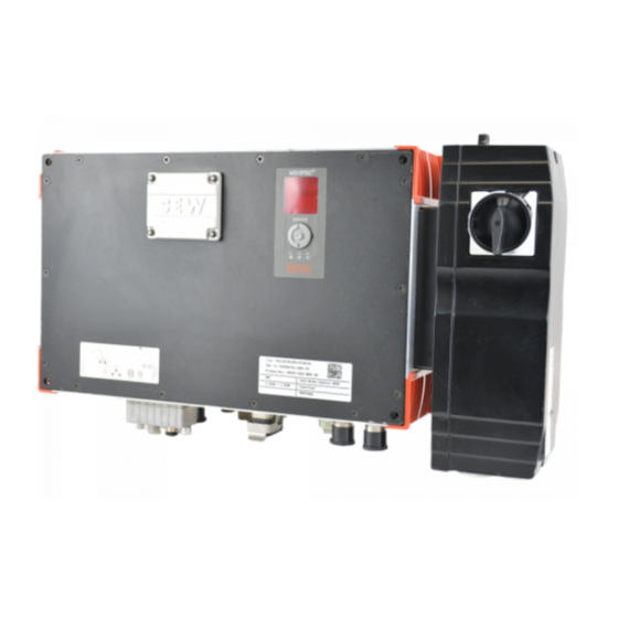
PZM2xA-A...-...-00 Power Interface Unit designation PZM2xA-A...-...-00 Power Interface Unit designation ® The unit designation of the MOVIPRO PZM2xA-A...-...-00 power interface comprises the following characteristic data: P ZM 2 x A - A ... - ... - 00 ® MOVIPRO connection: D02 = disconnection switch up to 25 A D03 = disconnection switch up to 40 A M13 = line and unit protection up to 5 A... -
Page 7: Power Interface Assignment
PZM2xA-A...-...-00 Power Interface Power interface assignment Power interface assignment The following overview illustrates the assignment of the individual power interfaces to ® the respective MOVIPRO units: ® MOVIPRO Power interface Part number up to 2.2 kW up to 4.0 kW up to 7.5 kW up to 11.0 kW up to 15.0 kW... -
Page 8: Scope Of Functions
PZM2xA-A...-...-00 Power Interface Scope of functions Scope of functions The power interface allows for the following functions: • Connection to the AC 400 V supply system • Connection to the 24 V backup voltage ® • DC 24 V output of the integrated power supply for the MOVIPRO self-supply without external DC 24 V cabling (jumper with DC 24 V backup voltage) •... -
Page 9: Power Interface - Mechanical Installation
PZM2xA-A...-...-00 Power Interface Power interface – mechanical installation 2.6.1 D.. disconnection switch The following disconnection switches are possible depending on the unit's power rating: Power Short designation Description up to 7.5 kW Disconnection switch up to 25 A up to 15.0 kW Disconnection switch up to 40 A 2.6.2 M.. - Page 10 PZM2xA-A...-...-00 Power Interface Power interface – mechanical installation 2.7.3 Mounting the power interface Use the following enclosed parts for assembly: • 2 × M5 × 30 SW8 screws ® Mount the power interface on the right side of the MOVIPRO unit (as viewed onto the unit front).
-
Page 11: Power Interface - Electrical Installation
PZM2xA-A...-...-00 Power Interface Power interface – electrical installation Power interface – electrical installation 2.8.1 General Information Observe the following notes on electrical installation: • Observe the general safety notes. • Strictly observe all instructions as to the technical data and the permissible condi- tions regarding the place of installation. - Page 12 PZM2xA-A...-...-00 Power Interface Power interface – electrical installation Connection to The following table provides information about this connection: ® MOVIPRO Function • AC 400 V input to supply units up to 15.0 • With signal contact for external maintenance switch •...
- Page 13 PZM2xA-A...-...-00 Power Interface Power interface – electrical installation Coding The following table shows the assignment of the different coding to the respective power ® interfaces and the corresponding MOVIPRO units: ® Power interface Power interface – coding of the connections MOVIPRO PZM2xA-A022-M13-00 2.2 kW...
- Page 14 PZM2xA-A...-...-00 Power Interface Power interface – electrical installation 2.8.4 Terminal strip of power interface The following table shows the connections of the power interface: [10] 9007201210059403 Terminal strip (power input terminal strip) Terminal cross sec- Name Function tion VO24 DC 24 V output Reference potential / DC 24 V output +24 V_C DC 24 V input...
- Page 15 PZM2xA-A...-...-00 Power Interface Power interface – electrical installation ® DC 24 V supply The MOVIPRO is equipped with a DC 24 V output that can be used to supply the ® MOVIPRO from the DC link. To use the 24 V supply from the DC link, you must jumper the following terminals: •...
-
Page 16: Power Interfaces - Technical Data
PZM2xA-A...-...-00 Power Interface Power interfaces – technical data Power interfaces – technical data 2.9.1 Basic unit The following table lists the technical data for the PZM2xA-A...-...-00 power interfaces: Power interface PZM2xA-A022- PZM2xA-A040- PZM2xA-A075- PZM2xA-A075- PZM2xA-A150- M13-00 M14-00 M16-00 D02-00 D03-00 Description 2.2 kW with line 4 kW with line... - Page 17 PZM2xA-A...-...-00 Power Interface Power interfaces – technical data 2.9.2 Power interface – dimension drawings The dimension drawings show the mechanical dimensions of the power interface in mm (in): M32 × 1.5 (2×) M25 × 1.5 (2×) 10 (0.39) 44 (1.7) 139 (5.47) 2052458379 2.9.3...
-
Page 18: Sensor/Actuator Box
Sensor/Actuator Box Sensor/Actuator Box The sensor/actuator box allows for connecting up to 8 sensors/actors to the ® ® MOVIPRO . It occupies only one connection for digital I/Os of the MOVIPRO unit. The sensor/actuator box provides one connection cable with M23 plug connector and M12 sockets for the sensors or actuators [1]. -
Page 19: Sensor/Actuator Box - Electrical Installation
Sensor/Actuator Box Sensor/actuator box – electrical installation Sensor/actuator box – electrical installation 3.1.1 Signals Connection The following table provides information about this connection: Function ® Signal transmission to a MOVIPRO unit Connection type M23, P insert 12-pole, female, 0°-coded Wiring diagram 2264822027 Assignment Name... - Page 20 Sensor/Actuator Box Sensor/actuator box – electrical installation Connection cables The following table shows the available cable lengths for the sensor/actuator box: Connection cable and component Length/ Cable Installation type Length 1 m: Part no. 1 330 926 9 Length 2 m: Part no. 1 330 927 7 Length 3 m: Part no.
-
Page 21: Technical Data Of The Sensor/Actuator Box
Sensor/Actuator Box Technical data of the sensor/actuator box Technical data of the sensor/actuator box The following tables show the technical data of the sensor/actuator box: Basic unit Nominal voltage DC 24 V Maximum operating voltage DC 30 V Current carrying capacity per slot total Operating voltage display... - Page 22 Sensor/Actuator Box Technical data of the sensor/actuator box 3.2.2 Dimension drawing The dimension drawing shows the mechanical dimensions of the sensor/actuator box in mm (in): 140 (5.5) 107 (4.2) 73 (2.9) 4.5 (0.2) Ø 4.5 (0.2) 9007200325600523 Addendum to the Operating Instructions – MOVIPRO®...
-
Page 23: Bw...-0..-0. External Braking Resistors
BW...-0..-0. External Braking Resistors BW...-0..-0. External Braking Resistors WARNING Electric shock The supply cables carry a high DC voltage (ca. DC 900 V). Severe or fatal injuries. • Only use cables provided by SEW-EURODRIVE. • Install the braking resistor cables according to the regulations. WARNING Hot surfaces. -
Page 24: Braking Resistors - Mechanical Installation
BW...-0..-0. External Braking Resistors Braking resistors – mechanical installation Braking resistors – mechanical installation 4.1.1 Mounting position The following table shows the permitted and prohibited mounting positions for the brak- ing resistors: Braking resistors Mounting positions BW100-004-00 BW033-012-01 BW050-008-01 BW017-024-02 4.1.2 Minimum clearance Calculate the mounting surfaces, the touch guard and the clearance according to the... - Page 25 BW...-0..-0. External Braking Resistors Braking resistors – mechanical installation 4.1.3 Mounting the braking resistors You can mount the braking resistors directly over the retaining plates. Note the following points during assembly: • Observe the safety notes. • Observe the required minimum distances and clearances. Use the following parts for assembly: •...
- Page 26 BW...-0..-0. External Braking Resistors Braking resistors – mechanical installation Sizes 1 and 2: 2110862475 4. Ground the housing of the braking resistor. Addendum to the Operating Instructions – MOVIPRO®...
- Page 27 BW...-0..-0. External Braking Resistors Braking resistors – mechanical installation 4.1.4 Mounting the braking resistors with mounting brackets (size 1 and 2 only) You can use the following mounting brackets to attach the braking resistors: • BW050-008-01 • BW033-012-01 • BW017-024-02 Note the following points during assembly: •...
-
Page 28: Technical Data Of The External Braking Resistors
BW...-0..-0. External Braking Resistors Technical data of the external braking resistors Technical data of the external braking resistors 4.2.1 Braking Resistor Assignment The following table illustrates the assignment of the external braking resistors to the re- ® spective MOVIPRO units: ®... - Page 29 BW...-0..-0. External Braking Resistors Technical data of the external braking resistors 4.2.3 Technical data according to UL The following tables list the technical data of the external braking resistors:according to Braking resistor BW100-004-00 BW050-008-01 BW033-012-01 BW017-024-02 Function Carrying off of regenerative energy Degree of protection IP65 Resistance...
- Page 30 BW...-0..-0. External Braking Resistors Technical data of the external braking resistors Size 1 braking The dimension drawing shows the mechanical dimensions of the size 1 braking resistor resistor in mm (in): Ø 9 (0.4) (2×) 12 (0.47) 542 (21.3) 550 (21.7) 2062339339 Addendum to the Operating Instructions –...
- Page 31 BW...-0..-0. External Braking Resistors Technical data of the external braking resistors Size 2 braking The dimension drawing shows the mechanical dimensions of the size 2 braking resistor resistor in mm (in): Ø 9 (0.4) (3×) 12 (0.47) 542 (21.3) 550 (21.7) 2062328587 Addendum to the Operating Instructions –...
- Page 32 BW...-0..-0. External Braking Resistors Technical data of the external braking resistors BW...-007, The dimension drawing shows the mechanical dimensions of the BW...-007, BW...015 BW...-015, and BW...-016 braking resistors in mm (in): BW...-016 M12×1.5 M20×1.5 82 (3.2) 160 (6.30) 200 (7.87) 225 (8.86) 117 (4.61) 25 (0.98)
- Page 33 BW...-0..-0. External Braking Resistors Technical data of the external braking resistors BW...-022 The dimension drawing shows the mechanical dimensions of the BW...-022 braking re- sistors in mm (in): M12x1.5 M20x1.5 82 (3.2) 268 (10.6) 306 (12.0) 331 (13.0) 117 (4.6) 80 (3.2) 82 (3.2) 22 (0.87)
-
Page 34: Jumper Plug
Jumper Plug Jumper Plug WARNING ® Safe disconnection of the MOVIPRO is not possible when the jumper plug is used. Severe or fatal injuries. ® • Use the jumper plug only if MOVIPRO is not required to perform any safety func- tions according to DIN EN ISO 13849-1. -
Page 35: Mounting Accessories
Mounting Accessories Handle option Mounting Accessories Handle option ® For easier handling, you can equip the MOVIPRO with handles: 2049840395 ® Depending on the size of the MOVIPRO , the handles are available in two lengths: ® Handle option Part number MOVIPRO housing height Handle option 270... -
Page 36: Mounting Brackets
Mounting Accessories Mounting brackets Mounting brackets ® You can use the mounting brackets to mount the MOVIPRO safely and easily: 658542347 Mounting brackets Part number ® MOVIPRO Mounting bracket kit, large (4 pieces) 1 270 830 5 Braking resistors: BW050-008-01 Mounting bracket kit, BW (4 pieces) 1 822 968 9 BW033-012-01... - Page 37 Mounting Accessories Mounting brackets 6.2.1 Mounting with mounting brackets Note the following points during assembly: • Strictly observe the safety notes contained in this documentation. • Observe the required minimum distances and clearances. Use the following parts for assembly: • The SEW-EURODRIVE "Large bracket mounting set"...
- Page 38 Mounting Accessories Mounting brackets The following figure shows the main mounting elements and dimensions in mm (in): 86.5 (3.41) Ø 15 (0.59) Ø 6.6 (0.26) 14.6 (0.575) 66 (2.6) 40.5 20 (0.79) (1.59) 114.5 (4.508) 36028797434827531 ® MOVIPRO Bore for Large mounting brackets M8 x 30 screw Holding fixture, e.g.
-
Page 39: Fan Subassembly
Fan Subassembly Fan Subassembly ® The fan is connected to the MOVIPRO externally. The axial fans are controlled auto- matically depending on the temperature. They are encapsulated, and their degree of protection is IP54. The following figure shows the fan subassembly: 36028797698977163 [1] Air baffle [2] Connection cables... -
Page 40: Fan Subassembly - Mechanical Installation
Fan Subassembly Fan subassembly – mechanical installation Fan subassembly – mechanical installation Use the following enclosed parts for assembly: • 6 × M5 × 75 screws • 6 × serrated lock washers Proceed as follows to mount the fan subassembly: 1. -
Page 41: Index
Index Index AC 400 V input Electrical installation Connection............12 Power interface..........11 Assignment Sensor/actuator box...........19 External braking resistors ........28 Embedded safety notes ...........4 Power interface ............7 Exclusion of liability..........5 External braking resistors ........23 Assignment ............28 Dimension drawings ..........29 Basic unit IEC data.............28 Power interface ............7 Mechanical installation........24 Brackets ..............36... - Page 42 Index Mechanical installation ..........9 Power interface External braking resistors ........24 Assignment ............7 Fan subassembly..........40 Basic unit ............7, 16 Cable routing .............11 Power interface ............9 Minimum clearance Certifications ............17 External braking resistance........24 Dimension drawings ..........17 Power interface ............9 Disconnection switch ...........9 Motor protection switch Electrical installation ..........11 M14/D16 ..............9...
- Page 43 Index Unit designation Power interface............6 Technical data External braking resistors ........28 Power interface ..........16 Sensor/actuator box...........21 X5001 ..............19 X5111 ..............40 X5502 ..............34 UL data External braking resistors ........29 0 ... 9 400 V input.............12 Addendum to the Operating Instructions – MOVIPRO®...
- Page 48 SEW-EURODRIVE—Driving the world SEW-EURODRIVE Driving the world SEW-EURODRIVE GmbH & Co KG P.O. Box 3023 D-76642 Bruchsal/Germany Phone +49 7251 75-0 Fax +49 7251 75-1970 sew@sew-eurodrive.com www.sew-eurodrive.com...
Need help?
Do you have a question about the Movipro PZM2xA-A Series and is the answer not in the manual?
Questions and answers