
Related Manuals for SEW-Eurodrive DFS11B PROFIBUS DP-V1


Summary of Contents for SEW-Eurodrive DFS11B PROFIBUS DP-V1
- Page 1 *20024940_0518* Drive Technology \ Drive Automation \ System Integration \ Services Manual DFS11B PROFIBUS DP-V1 with PROFIsafe Fieldbus Interface Edition 05/2018 20024940/EN...
- Page 2 SEW-EURODRIVE—Driving the world...
-
Page 3: Table Of Contents
Installing and removing option cards............ 21 ® Installing the DFS11B option card in MOVITRAC B ........... 22 ® 6.2.1 Connecting the system bus (SBus 1) between a MOVITRAC B and the DFS11B option ..................... 22 Manual – DFS11B PROFIBUS DP-V1 with PROFIsafe Fieldbus Interface... - Page 4 Parameterizing the PROFIsafe properties ........... 58 7.6.6 Description of the F-parameters.............. 58 7.6.7 Safety diagnostics using PROFIBUS DP ............. 60 7.6.8 Response times ................... 64 ® Procedure for starting up DFS11B with MOVIDRIVE B .......... 65 Manual – DFS11B PROFIBUS DP-V1 with PROFIsafe Fieldbus Interface...
- Page 5 Configuring a C1 master ..................... 107 9.4.1 Operating mode DP‑V1 ................ 107 9.4.2 Technical data of the GSD files for operation on PROFIBUS DP‑V1 .. 108 9.4.3 Error codes of DP‑V1 services .............. 109 Manual – DFS11B PROFIBUS DP-V1 with PROFIsafe Fieldbus Interface...
- Page 6 12.4 Safe output F-DO of DFS11B .................. 130 ® 12.5 STO input MOVIDRIVE MDX61B ................ 131 ® 12.6 STO input MOVITRAC B .................. 131 12.7 Dimension drawing of DFS11B in UOH11B gateway housing........ 131 Index ............................ 132 Manual – DFS11B PROFIBUS DP-V1 with PROFIsafe Fieldbus Interface...
-
Page 7: General Information
This is the formal structure of a safety note for a specific section: SIGNAL WORD Type and source of hazard. Possible consequence(s) if disregarded. • Measure(s) to prevent the hazard. Manual – DFS11B PROFIBUS DP-V1 with PROFIsafe Fieldbus Interface... -
Page 8: Structure Of Embedded Safety Notes
Read the documentation before you start working with the product. Content of the documentation This documentation contains additional safety-related information and conditions for operation in safety-related applications. Manual – DFS11B PROFIBUS DP-V1 with PROFIsafe Fieldbus Interface... -
Page 9: Other Applicable Documentation
Copyright notice © 2018 SEW‑EURODRIVE. All rights reserved. Unauthorized reproduction, modifica- tion, distribution or any other use of the whole or any part of this documentation is strictly prohibited. Manual – DFS11B PROFIBUS DP-V1 with PROFIsafe Fieldbus Interface... -
Page 10: Safety Notes
There is a risk that a change of parameters that cannot be detected externally may result in unexpected (but not uncontrolled) system behavior and may have a negative impact on operational safety, system availability, or data security. Manual – DFS11B PROFIBUS DP-V1 with PROFIsafe Fieldbus Interface... - Page 11 Use IT‑specific safety standards to increase access protection to the ports. For a port overview, refer to the respective technical data of the device in use. Manual – DFS11B PROFIBUS DP-V1 with PROFIsafe Fieldbus Interface...
-
Page 12: Introduction
Manual – DFS11B PROFIBUS DP-V1 with PROFIsafe Fieldbus Interface... -
Page 13: Acyclical Data Exchange Via Profibus Dp-V1
B provide numerous diagnostics options for startup and service. For example, you can use the integrated fieldbus monitor to control both setpoint values sent from the higher-level controller as well as the actual values. Manual – DFS11B PROFIBUS DP-V1 with PROFIsafe Fieldbus Interface... -
Page 14: Fieldbus Monitor
The fieldbus monitor in conjunction with the MOVITOOLS MotionStudio engineering software offers you an easy-to-use diagnostic tool for set- ting all drive parameters (including the fieldbus parameters) and for displaying the fieldbus and device status information in detail. Manual – DFS11B PROFIBUS DP-V1 with PROFIsafe Fieldbus Interface... -
Page 15: Integrated Safety Technology
This process dis- connects the rotating field generation for the respective motor. The individual mo- tor cannot develop any torque in this state even though the line voltage is still present. Manual – DFS11B PROFIBUS DP-V1 with PROFIsafe Fieldbus Interface... -
Page 16: Schematic Representation "Safety Concept For Movidrive
Before working on the electric part of the drive system, disconnect it from the supply voltage using an appropriate external disconnecting device and secure it against unintentional reconnection to the voltage supply. Manual – DFS11B PROFIBUS DP-V1 with PROFIsafe Fieldbus Interface... -
Page 17: Safety-Relevant Conditions
Whenever the system detects a fault, it reverts to a safe status, i.e. all safety-related process values (F-DO) are set to "0". In addition, the safety component is passivated. The "FS" LED (failsafe status) indicates the fault status (see chapter "Operating dis- plays"). Manual – DFS11B PROFIBUS DP-V1 with PROFIsafe Fieldbus Interface... -
Page 18: Voltage Supply
The voltage must be within the limits specified in the technical data. In addition, the following voltage values must not be ex- ceeded if a fault occurs (according to EN 60950): Max. DC 60 V, max. DC 120 V for 200 ms. Manual – DFS11B PROFIBUS DP-V1 with PROFIsafe Fieldbus Interface... -
Page 19: Assembly And Installation Notes
Users may only install or remove option cards for MOVIDRIVE® MDX61B sizes 1 to 6. • Plug the DFS11B option card into the fieldbus slot [1]. DFS11B 6052434187 [1] Fieldbus option slot Manual – DFS11B PROFIBUS DP-V1 with PROFIsafe Fieldbus Interface... -
Page 20: Before You Start
Keep the option card in its original packaging until immediately before you are ready to install it. • Hold the option card by its edges only. Do not touch any of the components. Manual – DFS11B PROFIBUS DP-V1 with PROFIsafe Fieldbus Interface... -
Page 21: Installing And Removing Option Cards
4. Insert the option card retaining bracket with the installed option card into the slot, pressing slightly so it is seated properly. Secure the option card retaining bracket with the two retaining screws. 5. To remove the option card, follow the instructions in reverse order. Manual – DFS11B PROFIBUS DP-V1 with PROFIsafe Fieldbus Interface... -
Page 22: Installing The Dfs11B Option Card In Movitrac B
6054461835 S12 = ON (terminating resistor activated) Terminal assignment X46:1 X26:1 SC11 SBus +, CAN high X46:2 X26:2 SC12 SBus -, CAN low X46:3 X26:3 GND, CAN GND X46:7 X26:7 DC 24 V Manual – DFS11B PROFIBUS DP-V1 with PROFIsafe Fieldbus Interface... - Page 23 MOVITRAC 1 2 3 4 5 6 7 FSC11B FSC11B 24V IO H L ^ 1 2 3 4 5 6 H L ^ 1 2 3 4 5 6 6054478603 Manual – DFS11B PROFIBUS DP-V1 with PROFIsafe Fieldbus Interface...
-
Page 24: Assembling And Installing The Dfs11B/Uoh11B Gateway Housing
• Point-to-point wiring is not permitted. Assembling and installing the DFS11B/UOH11B gateway housing INFORMATION Only SEW-EURODRIVE engineers are allowed to install or remove option cards in/ from the UOH11B gateway housing. Manual – DFS11B PROFIBUS DP-V1 with PROFIsafe Fieldbus Interface... - Page 25 Reserved X26:5 Reserved X26:6 GND, CAN GND X26:7 DC 24 V The gateway housing is supplied with DC 24 V via X26. Connect the bus terminating resistor at the end of the system bus connection. Manual – DFS11B PROFIBUS DP-V1 with PROFIsafe Fieldbus Interface...
-
Page 26: Connection And Terminal Description Of The Dfs11B Option
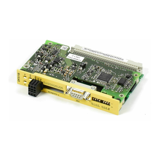
Connection and terminal description of the DFS11B option Connection and terminal description of the DFS11B option 6.4.1 Part number DFS11B PROFIBUS DP-V1 with PROFIsafe fieldbus interface option: 18209629 INFORMATION ® • The DFS11B option is only possible in connection with MOVITRAC ... - Page 27 LED H1 (red) System error (only for gateway functionality) LED H2 (green) Reserved ® X24 X terminal RS485 interface for diagnostics via PC and MOVITOOLS ® MotionStudio (only for MOVITRAC B) Manual – DFS11B PROFIBUS DP-V1 with PROFIsafe Fieldbus Interface...
-
Page 28: Safe Technology Wiring Diagrams
B) and one device of ® ® size ≥1 (MOVIDRIVE MDX61B or MOVITRAC B) and one BST safety-related brake module each. • Observe the corresponding operating instructions when using the BST safety-re- lated brake module. Manual – DFS11B PROFIBUS DP-V1 with PROFIsafe Fieldbus Interface... -
Page 29: Individual Wiring Of Movidrive
In addition, the following voltage values must not be exceeded if a fault occurs (according to EN 60950): Max. DC 60 V, max. DC 120 V for 200 ms. Manual – DFS11B PROFIBUS DP-V1 with PROFIsafe Fieldbus Interface... -
Page 30: Group Wiring Of Movidrive
The voltage must be within the limits specified in the technical data. In addition, the following voltage values must not be exceeded if a fault occurs (according to EN 60950): Max. DC 60 V, max. DC 120 V for 200 ms. Manual – DFS11B PROFIBUS DP-V1 with PROFIsafe Fieldbus Interface... -
Page 31: Connection To Profibus
• Apply the shielding of the bus cable on both ends. • Route signal and bus cables in separate cable ducts. Do not route them parallel to power cables (motor leads). Manual – DFS11B PROFIBUS DP-V1 with PROFIsafe Fieldbus Interface... -
Page 32: Bus Termination
If the DFS11B option is located at the start or end of a PROFIBUS segment and only one PROFIBUS cable is connected to the DFS11B, you have to use a connector with integrated bus terminating resistor. Switch on the bus terminating resistors for this PROFIBUS connector. Manual – DFS11B PROFIBUS DP-V1 with PROFIsafe Fieldbus Interface... -
Page 33: Setting The Profibus Station Address
→ Significance: 4 × 0 = 0 → Significance: 8 × 0 = 0 → Significance: 16 × 1 = 16 → Significance: 32 × 0 = 0 → Significance: 64 × 0 = 0 Manual – DFS11B PROFIBUS DP-V1 with PROFIsafe Fieldbus Interface... -
Page 34: Operating Displays Of The Dfs11B Option
DIP 2 Hz higher than 125 or to 0. switches. • Reset the inverter. Flashes No error, only display. The inverter performs a reset. 1 Hz Manual – DFS11B PROFIBUS DP-V1 with PROFIsafe Fieldbus Interface... - Page 35 Check configuration of the bus master. Flashing Acknowledgement required Acknowledge fault in the F-Host (reintegra- red / (A fault occurred in the tion) green safety part. Cause of the fault already remedied). Manual – DFS11B PROFIBUS DP-V1 with PROFIsafe Fieldbus Interface...
-
Page 36: Gateway Leds
Flashing Bus scan Gateway checks the bus. INFORMATION • LED H2 (green) is currently reserved. ® • X terminal X24 is the RS485 interface for diagnostics via PC and MOVITOOLS MotionStudio. Manual – DFS11B PROFIBUS DP-V1 with PROFIsafe Fieldbus Interface... -
Page 37: Procedure After Device Replacement
Make sure that the set address corresponds to the PROFIsafe address in STEP7 HWKONFIG. • Use the 2 – 2 DIP switches to set the PROFIBUS station address of the new op- tion card. Manual – DFS11B PROFIBUS DP-V1 with PROFIsafe Fieldbus Interface... -
Page 38: Project Planning And Startup
Use the GSD fileSEW_600C.GSD from the "DPV1" directory if you want to use the parameter setting options of DP-V1 in addition to the standard PROFIBUS DP com- ® munication to control the MOVIDRIVE This GSD file corresponds to GSD revision 4. Manual – DFS11B PROFIBUS DP-V1 with PROFIsafe Fieldbus Interface... -
Page 39: Project Planning Procedure
5. Enter the I/O or peripheral addresses for the configured data widths. After project planning, you can start PROFIBUS DP. The red BF LED (BUS FAULT) indicates the status of the project planning (OFF = project planning OK). Manual – DFS11B PROFIBUS DP-V1 with PROFIsafe Fieldbus Interface... -
Page 40: Dp Configurations For Movidrive Mdx61B
(PD4-PD10 can only be used with plus® IPOS ® 8 PD MOVIDRIVE control via 8 process 0x00 0x00 0xC0 0xC7 0xC7 data words (PD4-PD10 can only be used with plus® IPOS Manual – DFS11B PROFIBUS DP-V1 with PROFIsafe Fieldbus Interface... - Page 41 0xC0 0x87 0x87 0xC0 0xC6 0xC6 data words Parameterization via 8-byte parameter channel ® Param +8 PD MOVIDRIVE control via 8 process 0x00 0xC0 0x87 0x87 0xC0 0xC7 0xC7 data words Parameterization via 8-byte parameter channel Manual – DFS11B PROFIBUS DP-V1 with PROFIsafe Fieldbus Interface...
- Page 42 10 I/O bytes or 5 I/O words 5 process data words 12 I/O bytes or 6 I/O words 6 process data words 14 I/O bytes or 7 I/O words 7 process data words Manual – DFS11B PROFIBUS DP-V1 with PROFIsafe Fieldbus Interface...
- Page 43 For PROFIBUS DP, data communication between the programmable controller and drive engineering devices is usually carried out with the setting "Data integrity over en- tire length". Manual – DFS11B PROFIBUS DP-V1 with PROFIsafe Fieldbus Interface...
-
Page 44: Project Planning Of Profibus/Profisafe With Movitracb Or Gateway
Project planning tool DP master File name All DP project planning tools to EN For standard DP mas- SEW_6009.GSD 50170 (V2) ters Siemens S7 hardware configuration For all S7 DP masters Manual – DFS11B PROFIBUS DP-V1 with PROFIsafe Fieldbus Interface... -
Page 45: Profibus Dp Master Startup
You have the oppor- tunity to control the drives via process data and to read and write all parameters of the fieldbus interface via the parameter channel. Manual – DFS11B PROFIBUS DP-V1 with PROFIsafe Fieldbus Interface... - Page 46 The standard entries of the GSD file are based on the DFS11B "Auto setup" operating mode and allow process data widths of 3 PD per inverter. INFORMATION 3 PDs are always assigned to any SBus station. Manual – DFS11B PROFIBUS DP-V1 with PROFIsafe Fieldbus Interface...
- Page 47 Control via Drives 15 PD (15 PD) AS 6 Control via Drives 18 PD D1, D1 (18 PD) AS 7 Control via Drives 21 PD D4, D4 (21 PD) AS 8 Control via Drives 24 PD D7, D7 (24 PD) Manual – DFS11B PROFIBUS DP-V1 with PROFIsafe Fieldbus Interface...
- Page 48 C2, C2 C2, C2 × 3 PD) AS 8 Control via Drives (8 8 × 3 PD C2, C2 C2, C2 C2, C2 C2, C2 C2, C2 C2, C2 C2, C2 C2, C2 × 3 PD) Manual – DFS11B PROFIBUS DP-V1 with PROFIsafe Fieldbus Interface...
-
Page 49: Operating Mode Dp-V1
The drive inverters read the pro- cess input data, put it together and send it to the fieldbus master. The cycle time of the SBus communication requires 2 ms for each station. Manual – DFS11B PROFIBUS DP-V1 with PROFIsafe Fieldbus Interface... - Page 50 The following figure shows the data exchange between DP-V1 master, DFS and in- verter. 6064848395 Manual – DFS11B PROFIBUS DP-V1 with PROFIsafe Fieldbus Interface...
-
Page 51: Setting The Movidrive Mdx61B Drive Inverter
For example, all parameters can be set by the master programmable control- ler after power-on. Activation of the control signal source and setpoint source FIELDBUS is signaled to the machine control using the "Fieldbus mode active" bit in the status word. Manual – DFS11B PROFIBUS DP-V1 with PROFIsafe Fieldbus Interface... -
Page 52: Setting The Movitracb Frequency Inverter
DIØ1 – DIØ3 to NO FUNCTION. Setting the MOVITRAC B f requency inverter ® Setting the MOVITRAC B frequency inverter The following settings must be made for simple fieldbus operation. 6065562379 Manual – DFS11B PROFIBUS DP-V1 with PROFIsafe Fieldbus Interface... - Page 53 INFORMATION • Configure the parameter P881 SBus address to values 1 to 8 in ascending order. • The SBus address 0 is used by the DFS11B gateway and must therefore not be used. Manual – DFS11B PROFIBUS DP-V1 with PROFIsafe Fieldbus Interface...
-
Page 54: Configuring Profisafe With Step7
0 = x 0 = x 1 = x 0 = x 1 = x 1 = x 1 = x 1 = x 1 = x 1 = 1012 6065567883 Manual – DFS11B PROFIBUS DP-V1 with PROFIsafe Fieldbus Interface... -
Page 55: Installing The Gsd File
MOVITRAC DFS11B074 firmware UOH11B gateway housing option 1 DFS11B SEW_600C.GSD SEW_6009.GSD Once you have installed the GSD file, the module appears in the Hardware catalog of STEP7 HW Config under: 6065571339 Manual – DFS11B PROFIBUS DP-V1 with PROFIsafe Fieldbus Interface... -
Page 56: Configuring The Dfs11B In Hw Config
DFS11B" to the bus cable. If slot 1 is not configured, you can operate the DFS like the standard fieldbus module. No safety function via PROFIsafe is available in this configuration. 6066050443 Manual – DFS11B PROFIBUS DP-V1 with PROFIsafe Fieldbus Interface... -
Page 57: Project Planning For A New Configuration
The process data channel must always be configured. This channel is not safety-related. The following figure shows the described project planning of a new configuration. 6067928715 Manual – DFS11B PROFIBUS DP-V1 with PROFIsafe Fieldbus Interface... -
Page 58: Parameterizing The Profisafe Properties
This parameter allows F stations to check whether the safety class matches that of the F host. Safety circuits with different safety classes SIL 1 to SIL 3 (SIL = safety integrity level) are available for these safety-relevant cases according to the risk. Manual – DFS11B PROFIBUS DP-V1 with PROFIsafe Fieldbus Interface... - Page 59 For the DFS11B option, you can define the "F_WD_Time" parameter in steps from 1 ms to 10 s. Manual – DFS11B PROFIBUS DP-V1 with PROFIsafe Fieldbus Interface...
-
Page 60: Safety Diagnostics Using Profibus Dp
Switch HW Config to online mode. A mini icon [1] on the device symbol indicates devices with non-functioning PROFIsafe communication. 6515827211 • Double-clicking such a device displays the current module status (see following figure). Manual – DFS11B PROFIBUS DP-V1 with PROFIsafe Fieldbus Interface... - Page 61 Project planning and startup Configuring PROFIsafe with STEP7 6515830667 • The detected error is displayed in plain text [1] on the "DP slave diagnostics" tab. 6515834635 Manual – DFS11B PROFIBUS DP-V1 with PROFIsafe Fieldbus Interface...
- Page 62 Byte 11 provides diagnostics of the PROFIsafe layer. In this case, error number 40 hex indicates an incorrectly set F-address. Consequently, the PROFIsafe module de- tects an internal system error and indicates this via 02 hex in byte 13. Manual – DFS11B PROFIBUS DP-V1 with PROFIsafe Fieldbus Interface...
- Page 63 Falsche F-Parameter Version. F-Parameter set incorrect. / 71 Fehler im CRC1-Wert. CRC1-Fault. INFORMATION For more information on the meaning and remedy of error messages, refer to the manuals for the PROFIBUS-DP master manuals. Manual – DFS11B PROFIBUS DP-V1 with PROFIsafe Fieldbus Interface...
-
Page 64: Response Times
PROFIsafe cycle time • Processing time (cycle time) in the safety controller • PROFIsafe monitoring time "F_WD_Time" • Internal reaction time of the safe outputs • Response or switching time of the actuator Manual – DFS11B PROFIBUS DP-V1 with PROFIsafe Fieldbus Interface... -
Page 65: Procedure For Starting Up Dfs11B With Movidrive B
DFS11B with MOVIDRIVE ® Procedure for starting up DFS11B with MOVIDRIVE ® The following sections describe the startup procedure for MOVIDRIVE MDX61B with the DFS11B PROFIBUS option step-by-step. Manual – DFS11B PROFIBUS DP-V1 with PROFIsafe Fieldbus Interface... -
Page 66: Preliminary Work
Set the P876 PO data enable parameter to "Yes". Step 2: Configure PROFIBUS 1. Start the control manufacturer's software to configure the hardware (e.g. STEP7- HW Config). Manual – DFS11B PROFIBUS DP-V1 with PROFIsafe Fieldbus Interface... -
Page 67: Procedure For Starting Up Dfs11B With Movitracb (Gateway)
3. MOVITOOLS MotionStudio, version 5.40 or later Step 2: Install devices ® 1. Install MOVITRAC B according to the operating instructions: • Supply system cable • Motor cables • Braking resistor Manual – DFS11B PROFIBUS DP-V1 with PROFIsafe Fieldbus Interface... -
Page 68: Switch On The Devices With Dc 24 V Or Ac 400 V
Configuration" tab and check whether the "Auto setup" function has recog- nized all devices. If not, check • the SBus installation. • whether the terminating resistor is connected to the final device. • the SBus addresses of the individual devices. Manual – DFS11B PROFIBUS DP-V1 with PROFIsafe Fieldbus Interface... - Page 69 Activate device enable by setting control word 1 = 0x0006. ® If MOVITRAC B remains in "No Enable" condition, check the terminal assignment (parameter group P60x) and apply DC 24 V to more digital inputs if required. Manual – DFS11B PROFIBUS DP-V1 with PROFIsafe Fieldbus Interface...
-
Page 70: Profibus Dp Operating Characteristics
PROFIsafe safety telegram. Depending on the configuration, the maximum available expansion level enables the exchange of PROFIsafe safety data, the para- meter channel, and the process data between DP master and DFS11B as shown in the following figure. 6068637579 Manual – DFS11B PROFIBUS DP-V1 with PROFIsafe Fieldbus Interface... -
Page 71: Mapping The Dfs11B In The Address Range Of The Plc
"0". The following figure shows the input data in the PLC input address range. 6068643083 The following figure shows the MQS data in the PLC output address range. 6068712587 Manual – DFS11B PROFIBUS DP-V1 with PROFIsafe Fieldbus Interface... -
Page 72: F Periphery Db Of Profisafe Option Dfs
F periphery takes place, Provided that PASS_ON = "1". ACK_NEC After a fault has been corrected, the PROFIsafe option DFS is reintegrated, depending on ACK_NEC. • ACK_NEC = 0: Automatic reintegration • ACK_NEC = 1: Reintegration following acknowledgement by the user Manual – DFS11B PROFIBUS DP-V1 with PROFIsafe Fieldbus Interface... - Page 73 For service information purposes, the variable DIAG supplies non-failsafe information about faults that have occurred in the F control system. For further information, refer to the relevant F control system manual. Manual – DFS11B PROFIBUS DP-V1 with PROFIsafe Fieldbus Interface...
- Page 74 1: F-DO active 1 – 7 - Reserved Do not use! 0 – 7 - Reserved Do not use. • Input data: Byte Bit Name Default Function Comment 0, 1 0 – 7 - Reserved Do not use. Manual – DFS11B PROFIBUS DP-V1 with PROFIsafe Fieldbus Interface...
-
Page 75: Controlling The Movidrive
For more information about control via the process data channel, in particular re- ® garding the coding of the control and status word, refer to the "MOVIDRIVE MDX60B/61B Communication and Fieldbus Device Profile" manual. Manual – DFS11B PROFIBUS DP-V1 with PROFIsafe Fieldbus Interface... -
Page 76: Control Example With Movidrive Mdx61B Via Simatic S7
P831 is used to set the fault response that is triggered via the fieldbus timeout monit- oring function. The setting made here must correspond to the setting in the master system (S7: response monitoring). Manual – DFS11B PROFIBUS DP-V1 with PROFIsafe Fieldbus Interface... -
Page 77: Controlling The Movitracb Inverter (Gateway)
SFC14 and SFC15. Process data configuration STEP 7 access via 3 PD – 24 PD System functions SFC14/15 (length: 6 – 48 bytes) Param +3 PD – 24 PD System functions SFC14/15 (length 6 – 48 bytes for PD + 8 bytes for parameter) Manual – DFS11B PROFIBUS DP-V1 with PROFIsafe Fieldbus Interface... -
Page 78: Sbus Timeout
20, 22 and 24 to the output address POW 576 ... Note the length specification in bytes for the RECORD parameter. The length informa- tion must correspond to the configured length. //Start of cyclical program processing in OB1 Manual – DFS11B PROFIBUS DP-V1 with PROFIsafe Fieldbus Interface... - Page 79 RECORD := P#DB3.DBX 20.0 BYTE 6 //Pointer to DB/DW RET_VAL:= MW 32 //Result in flag word 32 Refer to the online help for STEP7 for further information about the system functions. Manual – DFS11B PROFIBUS DP-V1 with PROFIsafe Fieldbus Interface...
-
Page 80: Parameter Setting Via Profibus Dp
Byte 1 Byte 2 Byte 3 Byte 4 Byte 5 Byte 6 Byte 7 Manage- Subindex Index Index MSB data Data Data LSB data ment high Parameter index 4 byte data Manual – DFS11B PROFIBUS DP-V1 with PROFIsafe Fieldbus Interface... - Page 81 The service is executed as soon as the handshake bit received in the control card is the same as the one that was sent. Status bit 7 indicates whether the service was executed properly or whether errors occurred. Manual – DFS11B PROFIBUS DP-V1 with PROFIsafe Fieldbus Interface...
-
Page 82: Reading A Parameter Via Profibus Dp (Read)
Since this is a read service, the sent data bytes (bytes 4 to 7) and the data length (in the management byte) are ignored and do not need to be set. Manual – DFS11B PROFIBUS DP-V1 with PROFIsafe Fieldbus Interface... -
Page 83: Writing A Parameter Via Profibus Dp (Write)
As a result, a WRITE ser- vice on SEW inverters generally has the management byte coding 32hex or 72hex. 7 / MSB 0 / LSB Manual – DFS11B PROFIBUS DP-V1 with PROFIsafe Fieldbus Interface... -
Page 84: Parameter Setting Procedure With Profibus Dp
01110010XXX... → ← 00110010XXX... WRITE service is per- formed, handshake bit is changed. Service confirmation is ← 01110010XXX... received as the send and receive hand- shake bits are the same again. Manual – DFS11B PROFIBUS DP-V1 with PROFIsafe Fieldbus Interface... -
Page 85: Parameter Data Format
These return codes are described in detail in the "MOVIDRIVE MDX60B/61B Com- munication and Fieldbus Device Profile" manual and are not included in this docu- mentation. However, the following special cases can occur in connection with PROFIBUS. Manual – DFS11B PROFIBUS DP-V1 with PROFIsafe Fieldbus Interface... - Page 86 For Error class 8 = Other error, only Error code = 0 (Other error code) is defined. In this case, detailed identification is made using the ad- ditional code element. Manual – DFS11B PROFIBUS DP-V1 with PROFIsafe Fieldbus Interface...
-
Page 87: Special Cases Of Parameterization Errors
The following is a list of errors that can occur depending on the fieldbus interface used: • Incorrect coding of a service via parameter channel • Incorrect length specification of a service via parameter channel • Internal communication error Manual – DFS11B PROFIBUS DP-V1 with PROFIsafe Fieldbus Interface... - Page 88 Repeat the READ or WRITE service. If the error occurs again, briefly disconnect the inverter from the power supply and switch it on again. If this error occurs permanently, consult SEW Service. Manual – DFS11B PROFIBUS DP-V1 with PROFIsafe Fieldbus Interface...
-
Page 89: Profibus Dp-V1 Functions
The main features of PROFIBUS DP‑V1 are explained below. C1-Master C2-Master C2-Master Cyclic OUT Data Param PROFIBUS DP-V1 Param Cyclic IN Data Acyclic DP-V1 C2-Services Acyclic DP-V1 Acyclic DP-V1 C1-Services C2-Services Drive 172224651 Manual – DFS11B PROFIBUS DP-V1 with PROFIsafe Fieldbus Interface... -
Page 90: Class 1 Master (C1 Master)
Read data set WRITE Write data set C2 master Connection type: MSAC2 (master/slave acyclical C2) INITIATE Establish C2 connection ABORT Disconnect C2 connection READ Read data set WRITE Write data set Manual – DFS11B PROFIBUS DP-V1 with PROFIsafe Fieldbus Interface... -
Page 91: Dp-V1 Alarm Handling
The following figure shows the parameter setting channels for PROFIBUS DP-V1. C1-Master C2-Master C2-Master Acyclic DP-V1 C1-Services 8 Byte Param PROFIBUS DP-V1 Acyclic DP-V1 Acyclic DP-V1 C2-Services C2-Services Cyclic IN/Out cyclic Process Data Parameterbuffer Drive System 172229387 Manual – DFS11B PROFIBUS DP-V1 with PROFIsafe Fieldbus Interface... -
Page 92: Structure Of The Dp-V1 Parameter Channel
0x81 Request parameter (-) (PROFIdrive) 0x82 Change parameter (-) (PROFIdrive) ® 0xC0 SEW MOVILINK Service (-) Axis Unsigned8 0x00 – 0xFF Number of axis 0 – 255 No. of Para- Unsigned8 0x01 – 0x13 1 – 19 DWORDs (240 DP‑V1 data bytes) meters Manual – DFS11B PROFIBUS DP-V1 with PROFIsafe Fieldbus Interface... - Page 93 0x43 Double word 0x44 Error No. of Values Unsigned8 0x00 – 0xEA Quantity 0 – 234 Error Value Unsigned16 0x0000 – 0x0064 PROFIdrive-Errorcodes ® 0x0080 + MOVILINK -AdditionalCode Low ® For SEW MOVILINK 16 Bit error value Manual – DFS11B PROFIBUS DP-V1 with PROFIsafe Fieldbus Interface...
-
Page 94: Parameterization Procedure Via Data Set 47
(parameter request) Parameter Request WRITE.res without data READ.req DS47 without data Parameter Processing READ.res(-) without data READ.req DS47 without data Parameter Parameter READ.res(+) Response Response with data (parameter response) 172315019 Manual – DFS11B PROFIBUS DP-V1 with PROFIsafe Fieldbus Interface... -
Page 95: Dp-V1 Master Processing Sequence
PROFIBUS interface. This ® mechanism can be used, for example, by the SEW MQP bus modules for MOVIMOT ® or UFP for MOVITRAC Manual – DFS11B PROFIBUS DP-V1 with PROFIsafe Fieldbus Interface... - Page 96 The actual service is defined by the data set element Attribute in the MOVILINK para- meter channel. The high nibble of this element corresponds to the service nibble in the management byte of the DP parameter channel. Manual – DFS11B PROFIBUS DP-V1 with PROFIsafe Fieldbus Interface...
- Page 97 Service READ.request Description Slot_Number 0 Random, (is not evaluated) Index Index of the data set; constant index 47 Length 10 byte user data in response buffer Manual – DFS11B PROFIBUS DP-V1 with PROFIsafe Fieldbus Interface...
- Page 98 Double word No. of values 0x01 Change 1 parameter word 12, 13 Value HiWord 0x0000 Higher-order part of the parameter value 14, 15 Value LoWord 0x0BB8 Lower-order part of the parameter word Manual – DFS11B PROFIBUS DP-V1 with PROFIsafe Fieldbus Interface...
- Page 99 0x01 Mirrored reference number from the paramet- erization request ® Response ID 0x40 Positive MOVILINK response Axis 0x00 Reflected axis number; 0 for single axis No. of parameters 0x01 1 parameter Manual – DFS11B PROFIBUS DP-V1 with PROFIsafe Fieldbus Interface...
- Page 100 No. of values 0x01 1 error code ® 6, 7 Error value 0x0811 MOVILINK return code e.g. Error class 0x08, Add. code 0x11 ® (see section "MOVILINK parameterization re- turn codes for DP-V1") Manual – DFS11B PROFIBUS DP-V1 with PROFIsafe Fieldbus Interface...
-
Page 101: Movilink
Parameter may only be changed with deactivated auto setup 0x0505 Incorrect coding of management and reserved byte 0x0602 Communication error between inverter system and fieldbus option card 0x0502 Timeout of secondary connection (e.g. during reset or with Sys-Fault) Manual – DFS11B PROFIBUS DP-V1 with PROFIsafe Fieldbus Interface... -
Page 102: Profidrive Parameter Requests
Use the MOVILINK service WRITE Para- meter volatile if parameters must be written cyclically at short intervals. With this ser- vice, you only alter the parameter values in the RAM of the inverter. Manual – DFS11B PROFIBUS DP-V1 with PROFIsafe Fieldbus Interface... - Page 103 The parameter value for index 8300 (firmware ver- sion) is returned as an example. Service READ.request Description Slot_Number Random (is not evaluated) Index Index of the data set; constant index 47 Length 10 byte user data in response buffer Manual – DFS11B PROFIBUS DP-V1 with PROFIsafe Fieldbus Interface...
- Page 104 Double word No. of values 0x01 Change 1 parameter value 12, 13 Value HiWord 0x0000 Higher-order part of the parameter value 14, 15 Value LoWord 0x0BB8 Lower-order part of the parameter word Manual – DFS11B PROFIBUS DP-V1 with PROFIsafe Fieldbus Interface...
- Page 105 Negative response for "Change Parameter" Axis 0x00 Reflected axis number; 0 = Single axis No. of parameters 0x01 1 parameter Format 0x44 Error No. of values 0x01 1 error code Manual – DFS11B PROFIBUS DP-V1 with PROFIsafe Fieldbus Interface...
- Page 106 (PROFIdrive Profile V2: name cannot be read in cyclic data transfer). 0x0F No text assignment Access to text assignment that is not accessible available (parameter value exists). 0x10 Reserved (PROFIdrive Profile V2: no PPO write). Manual – DFS11B PROFIBUS DP-V1 with PROFIsafe Fieldbus Interface...
-
Page 107: Configuring A C1 Master
PROFIBUS DP. This ensures mixed mode for DP-V1 and DP-capable modules. De- pending on the master functionality, a DP-V1 capable station, that was configured us- ing the DP-V1 GSD file, can run in the "DP" operating mode. Manual – DFS11B PROFIBUS DP-V1 with PROFIsafe Fieldbus Interface... -
Page 108: Technical Data Of The Gsd Files For Operation On Profibus Dp-V1
Supported data set: Index 47 Supported slot number: Recommendation: 0 Manufacturer code: 10A hex (SEW-EURODRIVE) Profile ID: C2 response timeout 1 s Max. length C1 channel: 240 bytes Max. length C2 channel: 240 bytes Manual – DFS11B PROFIBUS DP-V1 with PROFIsafe Fieldbus Interface... -
Page 109: Error Codes Of Dp-V1 Services
0xC = resource 0x0 = read constraint conflict 0x1 = write constraint conflict 0x2 = resource busy 0x3 = resource unavailable 0x4..0x7 = reserved 0x8..0xF = user specific 0xD...0xF = user specific Manual – DFS11B PROFIBUS DP-V1 with PROFIsafe Fieldbus Interface... - Page 110 Communication channel via interface adapter to SBus (CAN) or serial Engineering via interface adapters If your device supports the "SBus" or "Serial" communication options, you can use a suitable interface adapter for engineering. Manual – DFS11B PROFIBUS DP-V1 with PROFIsafe Fieldbus Interface...
-
Page 111: Operation Of Movitools Motionstudio
These devices must have been configured in the configuration software SIMATIC Manager (from the STEP 7 software package of Siemens). You can select the configured devices in the tool "HW Config" and call ® MOVITOOLS MotionStudio as a so-called "device tool". Manual – DFS11B PROFIBUS DP-V1 with PROFIsafe Fieldbus Interface... -
Page 112: First Steps
ð The following window opens. 9007217492118283 2. From the drop-down list [1], select the communication type. 3. Activate the selected communication type [2]. 4. To edit the settings of the selected communication type, click the button [3]. Manual – DFS11B PROFIBUS DP-V1 with PROFIsafe Fieldbus Interface... -
Page 113: Selecting The Communication Mode (Online Or Offline)
The connection mode is "online". The device has been scanned in the network view. Proceed as follows: 1. Select the device (in this example the power section [1]) in the network view. 2. Right-click to open the context menu. 9007201701091851 Manual – DFS11B PROFIBUS DP-V1 with PROFIsafe Fieldbus Interface... -
Page 114: Connection Mode
(or the manual) of MOVITOOLS MotionStudio. INFORMATION Project management commands (such as "download" and "upload"), the online device status, and the "device scan" work independently of the set connection mode. Manual – DFS11B PROFIBUS DP-V1 with PROFIsafe Fieldbus Interface... - Page 115 [1] of your engineering PC [3]. Offline tools • Execute the "Download (PC → device)" function if you want to transfer the changes to your device [4] as well. Check the para- meterization afterwards. Manual – DFS11B PROFIBUS DP-V1 with PROFIsafe Fieldbus Interface...
-
Page 116: Overview
SIMATIC S7 [2] does not perform any routing. Advantage The C2 master works independently of the C1 master. This means you can establish a communication with your devices even when the C1 master fails. Manual – DFS11B PROFIBUS DP-V1 with PROFIsafe Fieldbus Interface... -
Page 117: Additionally Required Hardware And Software
SIMATIC NET versions and operating system INFORMATION The following description might deviate slightly (in part due to the language) depend- ing on the SIMATIC NET version and the operating system in use. Manual – DFS11B PROFIBUS DP-V1 with PROFIsafe Fieldbus Interface... - Page 118 5. Make sure that all bus stations were parameterized correctly. ® 6. Open the MOVITOOLS MotionStudio engineering software. ® 7. Set the communication parameters in MOVITOOLS MotionStudio. Refer to the following section "Configuring communication via PROFIBUS". Manual – DFS11B PROFIBUS DP-V1 with PROFIsafe Fieldbus Interface...
-
Page 119: Configuring Communication Via Profibus
1. Make sure that all the required settings have been made in the project planning software. ® 2. Start MOVITOOLS MotionStudio and create a project following the instructions described in the section "First Steps". 3. Click "Configure communication connections" toolbar. 1143173387 Manual – DFS11B PROFIBUS DP-V1 with PROFIsafe Fieldbus Interface... -
Page 120: Communication Parameters For Profibus Dp/Dp-V1
3. Select the device you want to parameterize. 4. Choose the command [Startup] > [Parameter tree] from the context menu. ð This opens the "Parameter tree" view on the right section of the screen. Manual – DFS11B PROFIBUS DP-V1 with PROFIsafe Fieldbus Interface... -
Page 121: Starting Up Devices (Online)
4. Choose the command [Startup] > [Startup] from the context menu. ð The startup assistant is displayed. 5. Follow the instructions of the startup wizard and then load the startup data into your device. Manual – DFS11B PROFIBUS DP-V1 with PROFIsafe Fieldbus Interface... -
Page 122: Fault Diagnostics
Are the bus addresses the same? NO → ↓ You may have configured an incorrect device type or defined the configuration incorrectly. ↓ Delete the project planning for the inverter from the DP network. ↓ Manual – DFS11B PROFIBUS DP-V1 with PROFIsafe Fieldbus Interface... - Page 123 Use P094 to P097 (setpoint description PO1 to PO3) to check whether the setpoints sent by the controller are received correctly. To do so, send a setpoint other than 0 as a test in each output word. ↓ Setpoints received? YES → ↓ Manual – DFS11B PROFIBUS DP-V1 with PROFIsafe Fieldbus Interface...
-
Page 124: Fault List In Gateway Operation
Undefined SBus communic- opcode ation stopped Protection SBus communic- fault ation stopped Illegal word SBus communic- operand ac- ation stopped cess Illegal in- SBus communic- struction ac- ation stopped cess Manual – DFS11B PROFIBUS DP-V1 with PROFIsafe Fieldbus Interface... -
Page 125: Fault List - Profisafe Dfs11B Option
11.3 Fault list – PROFIsafe DFS11B option Fault Designation Response Cause Measure code No error – – – Manual – DFS11B PROFIBUS DP-V1 with PROFIsafe Fieldbus Interface... - Page 126 Switch the 24 V voltage off puts) and on again • F-DIx = 0 • Reintegration of DFS11B (→ safe state) • If the fault occurs again, • Passivation of contact SEW Service. DFS11B Manual – DFS11B PROFIBUS DP-V1 with PROFIsafe Fieldbus Interface...
- Page 127 The DFS11B option is not failsafe out- F_Dest_Add to configured compatible with the desired puts) value (configured) safety functions • F-DIx = 0 • Contact SEW Service (→ safe state) • Passivation of DFS11B Manual – DFS11B PROFIBUS DP-V1 with PROFIsafe Fieldbus Interface...
-
Page 128: Technical Data
Max. 8 bytes Diagnostics data • Standard diagnostics: 6 bytes ® Tools for startup • MOVITOOLS MotionStudio engineering software • DBG11B keypad F address See chapter "Connection and terminal description" Ambient temperature 0 – 55 °C Manual – DFS11B PROFIBUS DP-V1 with PROFIsafe Fieldbus Interface... -
Page 129: Dfs11B For Movitracb And Uoh11B Gateway Housing
Data) DP configurations for See section "Configuring process data" in chapter "Configuring the DDLM_Chk_Cfg PROFIBUS DP interface" Diagnostics data Standard diagnostics: 6 bytes ® Tools for startup MOVITOOLS MotionStudio engineering software Manual – DFS11B PROFIBUS DP-V1 with PROFIsafe Fieldbus Interface... -
Page 130: Safety Characteristic Values Dfs11B Fieldbus Interface
Load resistance range 24 kΩ – 1 kΩ Voltage limitation when Typically −70 V switching off inductive loads Response time (command ≤ 25 ms via PROFIsafe → the out- put switches) Maximum line length 30 m Manual – DFS11B PROFIBUS DP-V1 with PROFIsafe Fieldbus Interface... -
Page 131: Sto Input Movidrive Mdx61B
Time to inhibit output stage BG0 = 20 ms BG1 – 5 = 100 ms Time for restart 200 ms 12.7 Dimension drawing of DFS11B in UOH11B gateway housing DFS11B 22.5 6094336139 All dimensions in mm. Manual – DFS11B PROFIBUS DP-V1 with PROFIsafe Fieldbus Interface... -
Page 132: Index
Safety diagnostics using PROFIBUS DP .. 60 Configuring the PROFIBUS DP interface .... 45 Embedded safety notes......... 8 Configuring the PROFIBUS option card .... 13 ® Engineering, MOVITOOLS MotionStudio .. 110 Manual – DFS11B PROFIBUS DP-V1 with PROFIsafe Fieldbus Interface... - Page 133 LEDs............... 34 Reading/changing device parameters.. 120 PROFIBUS connection........ 31 Setting the connection mode...... 114 Baud rates greater than 1.5 MBaud .... 31 Starting up device......... 121 Bus termination .......... 32 Tasks............ 110 Manual – DFS11B PROFIBUS DP-V1 with PROFIsafe Fieldbus Interface...
- Page 134 Shielding and routing bus cables ...... 31 Operating mode DP-V1 ........ 49 Siemens Startup of the PROFIBUS DP master .... 45 Additional hardware and software .... 117 Communication via C2 master ..... 116 Manual – DFS11B PROFIBUS DP-V1 with PROFIsafe Fieldbus Interface...
- Page 135 Addressing connected inverters ..... 95 DP-V1 master processing sequence.... 95 UOH11B gateway housing ® MOVILINK parameter requests .... 96 Mounting and installation........ 25 Parameterization procedure via data set 47... 94 Use, designated .......... 10 Manual – DFS11B PROFIBUS DP-V1 with PROFIsafe Fieldbus Interface...
- Page 140 SEW-EURODRIVE—Driving the world SEW-EURODRIVE GmbH & Co KG Ernst-Blickle-Str. 42 76646 BRUCHSAL GERMANY Tel. +49 7251 75-0 Fax +49 7251 75-1970 sew@sew-eurodrive.com www.sew-eurodrive.com...
Need help?
Do you have a question about the DFS11B PROFIBUS DP-V1 and is the answer not in the manual?
Questions and answers