Winmate IK70 User Manual
Mini-itx sbc with intel 7th gen. core i3/i5/i7 processor.
Hide thumbs
Also See for IK70:
- User manual (120 pages) ,
- User manual (108 pages) ,
- User manual (100 pages)
Table of Contents
Advertisement
Quick Links
Download this manual
See also:
User Manual
Advertisement
Table of Contents

Subscribe to Our Youtube Channel
Related Manuals for Winmate IK70


Summary of Contents for Winmate IK70
- Page 1 All manuals and user guides at all-guides.com IK70 Motherboard Mini-ITX SBC with Intel® 7th Generation Core i3/i5/i7 processor, HDMI, Display Port, LVDS, Dual Giga Ethernet, USB 3.0 and NGFF Interface V110 User Manual Version 1.2 9171111I103R...
-
Page 2: Table Of Contents
All manuals and user guides at all-guides.com USER MANUAL CONTENTS CONTENTS PREFACE ..............................- 4 - ABOUT THIS USER MANUAL ........................- 8 - CHAPTER 1: GENERAL INFORMATION ....................- 10 - 1.1 I ............................ - 10 - NTRODUCTION 1.2 F ............................ - Page 3 All manuals and user guides at all-guides.com USER MANUAL CONTENTS 3.2 G ..........................- 42 - RAPHIC RIVER 3.3 M (ME) .NET F ..............- 46 - ANAGEMENT NGINE RAMEWORK RIVER 3.4 A ............................ - 50 - UDIO RIVER 3.5 E ..........................
-
Page 4: Preface
All manuals and user guides at all-guides.com USER MANUAL PREFACE PREFACE Copyright Notice No part of this document may be reproduced, copied, translated, or transmitted in any form or by any means, electronic or mechanical, for any purpose, without the prior written permission of the original manufacturer. - Page 5 All manuals and user guides at all-guides.com USER MANUAL PREFACE Packing List Before using this Motherboard, please make sure that all the items listed below are present in your package: IK0 Motherboard User Manual & Driver CD If any of these items are missing or damaged, contact your distributor or sales representative immediately.
- Page 6 All manuals and user guides at all-guides.com USER MANUAL PREFACE Advisory Conventions Four types of advisories are used throughout the user manual to provide helpful information or to alert you to the potential for hardware damage or personal injury. These are Notes, Important, Cautions, and Warnings. The following is an example of each type of advisory.
- Page 7 All manuals and user guides at all-guides.com USER MANUAL PREFACE Safety Precautions CAUTION Always ground yourself to remove any static charge before touching the CPU card. Modern electronic devices are very sensitive to static electric charges. As a safety precaution, use a grounding wrist strap at all times.
-
Page 8: About This User Manual
This User Manual provides information about using the IK70 Motherboard. The documentation set for the IK70 Motherboard provides information for specific user needs, and includes: IK70 Motherboard User Manual – contains detailed description on how to use the motherboard, its components and features. NOTE: Some pictures in this guide are samples and can differ from actual product. -
Page 9: Chapter 1: General Information
All manuals and user guides at all-guides.com USER MANUAL CHAPTER 1 GENERAL INFORMATION GENERAL INFORMATION This chapter includes the IK70 Motherboard background information. Introduction Features Motherboard Specifications Functional Description Physical Description - 9 -... -
Page 10: Introduction
This chapter includes the IK70 Motherboard background information. 1.1 Introduction Thank you for choosing the IK70 Motherboard. The IK70 Motherboard is powered by Intel® C236 chipset, 17x17 mm, and Socket G3 Intel® 7th Generation Core i7/i5/i3 Processor. The Intel®7th Generation Core™ processor based on 64-bit, multi-core processors built on 22-nanometer process technology. -
Page 11: Motherboard Specifications
All manuals and user guides at all-guides.com USER MANUAL CHAPTER 1 GENERAL INFORMATION 1.3 Motherboard Specifications Model Name IK70 Socket LGA 1151 Intel® i7/ i5 / i3 processor Chipset Intel® C236 System 2 x SO-DIMM socket ® socket DDR4-1866/2133 ECC Memory Max. - Page 12 Temp. Environment Storage -40°C ~ 70°C Considerations Temp. Operating 10% ~ 95%, non-condensing Humidity Power Input +12V Power Input Power Power Management Maximum 50W Consumption IK70-100 Single Board Computer Packing List Standard IK70 Manual & Driver CD - 12 -...
-
Page 13: Functional Description
All manuals and user guides at all-guides.com USER MANUAL CHAPTER 1 GENERAL INFORMATION 1.4 Functional Description Function block (V110) - 13 -... -
Page 14: Physical Description
All manuals and user guides at all-guides.com USER MANUAL CHAPTER 1 GENERAL INFORMATION 1.5 Physical Description Board Dimensions (V110) - 14 -... -
Page 15: Chapter 2: Hardware Installation
USER MANUAL CHAPTER 2 HARDWARE INSTALLATION HARDWARE INSTALLATION This chapter provides information on how to use jumpers and connectors on the IK70 motherboard. 2.1 Motherboard Components 2.2 Memory Module Installation 2.3 I/O Equipment Installation 2.4 Jumper Settings 2.5 Motherboard Connectors... -
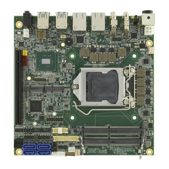
Page 16: Motherboard Components
HARDWARE INSTALLATION CHAPTER 2: HARDWARE INSTALLATION This chapter provides information on how to use jumpers and connectors on the IK70 Motherboard. Be cautious while working with these modules. Carefully read the content of this chapter in order to avoid any damages. -
Page 17: I/O Side
All manuals and user guides at all-guides.com USER MANUAL CHAPTER 2 HARDWARE INSTALLATION 2.1.2 I/O Side 2.1.3 Solder Side - 17 -... -
Page 18: Memory Module (So-Dimm) Installation
HARDWARE INSTALLATION 2.2 Memory Module (SO-DIMM) Installation The IK70 SBC Motherboard has two 260-pin SODIMM slot. The socket supports DDR4. When installing the memory unit, please follow the steps below: 1. Firmly insert the SO-DIMM at an angle of about 30-degree into the slot. Align the SO-DIMM with the slot until it is fully inserted. -
Page 19: I/O Equipment Installation
HARDWARE INSTALLATION 2.3 I/O Equipment Installation 2.3.1 12V DC in The IK70 Motherboard allows plugging 12V DC-IN jack on the board without another power module converter under power consumption by Intel® 7th Generation Core i7/i5/i3 Processor and C236 chipset. 2.3.2 Serial COM Port Four COM Port Pin Headers build in the motherboard. -
Page 20: Jumper Settings
All manuals and user guides at all-guides.com USER MANUAL CHAPTER 2 HARDWARE INSTALLATION 2.4 Jumper Settings This section explains how to set jumpers for correct configuration of the motherboard. NOTE: A pair of needle nose pliers may be helpful when working with jumpers. If you have any doubts about the best hardware configuration for your application, contact your local distributor or sales representative before you make any changes. -
Page 21: Jp1: Panel Power Select
All manuals and user guides at all-guides.com USER MANUAL CHAPTER 2 HARDWARE INSTALLATION 2.4.1 JP1: Panel Power Select Pin № Name 1-2 (Default) +3.3V +12V 2.4.2 JP2: Backlight Power Select Pin № Name 1-2 (Default) +12V 2.4.3 JP3: Backlight Dimming Select Pin №... -
Page 22: Clr_Cmos: Clear Cmos Jumper
All manuals and user guides at all-guides.com USER MANUAL CHAPTER 2 HARDWARE INSTALLATION 2.4.5 CLR_CMOS: Clear CMOS Jumper Remember to set jumper back to Normal before turning on the power supply. CAUTION TURN OFF the power supply before setting Clear CMOS. Pin №... -
Page 23: Mainboard Connectors
All manuals and user guides at all-guides.com USER MANUAL CHAPTER 2 HARDWARE INSTALLATION 2.5 Mainboard Connectors 2.5.1 Internal Front Side Connectors Connectors Label Function Note Power 4P Wafer Wafer 4p dip QJ3119C-WFB1-4F vertical HDMI Port Connector H:15mm Display Port Connector 3VD21203-H7U0-4H SHB Express PCIEx16 16x164p180°2EG08217-D2D... - Page 24 All manuals and user guides at all-guides.com USER MANUAL CHAPTER 2 HARDWARE INSTALLATION SATA_PWR1, SATA Power Connector 2*5p P:2.0mm DIP 180° SATA_PWR2 FAN1, FAN2 Fan Connector 3P 2.54mm DIP 180° ASAA82X-EASB0-7H 9.2mm 1.2V DDR4 SO-DIMM AS0AB26-H2SB-7H 5.2mm AS0AB26-H2SB-7H 5.2mm 1.2V 1.2V SMT USB2.0 Wafer 2*4p P:2.0mm DIP 180o...
- Page 25 All manuals and user guides at all-guides.com USER MANUAL CHAPTER 2 HARDWARE INSTALLATION 2.5.1.2 CN6: SHB Express PCIEx16 Side B Description Side A Description SMB_SHB_CLK PCIE 12V power SMB_SHB_DATA External pull down Side B Side A PCIE 12V power PCIE 12V power Side B Side A SHB_TDI...
- Page 26 All manuals and user guides at all-guides.com USER MANUAL CHAPTER 2 HARDWARE INSTALLATION HSOP_6 SHB_PCIE_A6_TXP PCIE Group A TX6+ Side A CLK_PCIE_SHB_A2_P PCIE Group A TX6- Side B Side A CLK_PCIE_SHB_A2_N PCIE Group A RX6+ Side B Side A CLK_PCIE_SHB_A3_P PCIE Group A RX6- Side B Side A...
- Page 27 All manuals and user guides at all-guides.com USER MANUAL CHAPTER 2 HARDWARE INSTALLATION 2.5.1.3 CN8: NGFF M.2 KEY E Connector IK70 Mini-PCIe connector supports 2 Mini-PCIe card application: PCIe I/F + USB 2.5.1.4 CN9: Digital Input / Digital Output Pin № Signal Name Pin №...
- Page 28 All manuals and user guides at all-guides.com USER MANUAL CHAPTER 2 HARDWARE INSTALLATION 2.5.1.6 CN12: LVDS Connector CN12 Pin № Signal Name Pin № Signal Name LCDVDD LVDS0_TX0_N LCDVDD LVDS0_TX0_P LCDVDD LVDS0_TX1_N LVDS0_TX1_P LVDS0_TX2_N LVDS0_TX2_P LVDS0_CLK_N LVDS0_CLK_P LVDS0_TX3_N LVDS0_TX3_P LVDS1_TX0_N LVDS1_TX0_P LVDS1_TX1_N LVDS1_TX1_P...
- Page 29 All manuals and user guides at all-guides.com USER MANUAL CHAPTER 2 HARDWARE INSTALLATION 2.5.1.7 CN13: Backlight Connector Pin № Signal Name +BKLPWR_R +BKLPWR_R +BKLPWR_R BRIGHT BLON_5V 2.5.1.8 CN14: Backlight Brightness Control VR Knob Pin № Signal Name +V5S VRD_ADC 2.5.1.9 CN15, CN16, CN17: Power Output Wafer - 29 -...
- Page 30 All manuals and user guides at all-guides.com USER MANUAL CHAPTER 2 HARDWARE INSTALLATION 2.5.1.10 CN18: RTC Wafer Pin № Signal Name BACKUP_VBAT 2.5.1.11 CN20, CN21: USB2.0 Wafer Signal Signal Signal Name Signal № Name № Name № № Name USB_VCC USB_VCC9 USB_VCC8 USB_VCC...
- Page 31 All manuals and user guides at all-guides.com USER MANUAL CHAPTER 2 HARDWARE INSTALLATION 2.5.1.14 COM1, COM2, COM3, COM4: Internal RS232 COM The serial port which is Winbond I/O support is RS232 only. Signal Signal Signal Signal № Name № Name №...
- Page 32 All manuals and user guides at all-guides.com USER MANUAL CHAPTER 2 HARDWARE INSTALLATION 2.5.1.15 PANEL 1: Front Panel Pin Header Pin № Signal Name Pin № Signal Name PW_LED+ HD_LED+ HD_LED- PW_BT BRI+ RST-BT BRI- 5VSB 2.5.1.16 SATA1, SATA2, SATA3, SATA4: SATA Connector Pin №...
- Page 33 All manuals and user guides at all-guides.com USER MANUAL CHAPTER 2 HARDWARE INSTALLATION 2.5.1.18 FAN1, FAN2: Fan Connector FAN1 FAN2 2.5.1.19 J2: DDR4 SO-DIMM 2.5.1.20 J3: DDR4 SO-DIMM - 33 -...
-
Page 34: External I/O Side Connectors
Clear COM, Reset Button USB1, USB2 USB 3.0 USB Type A 2.5.2.1 CN1 (Power 4P Terminal Block Connector The DC power input for the IK70 Motherboard allows a voltage input of 12V DC. Pin № Signal Name Pin № Signal Name 12VDC 12VDC 2.5.2.2 CN3/ HDMI1 (HDMI 1.4a) - Page 35 Lane 3+ Lane 3- AUX_EN_N AUX+ AUX- Hot Plug +3.3V 2.5.2.4 CN4 (Audio Jack) IK70 has two stereo audio ports with phone jack connectors, one is Line-out, and the other one is Mic-in. Color Signal Name Line-out Mic-in CN24 CN23...
- Page 36 HARDWARE INSTALLATION 2.5.2.5 LAN1, LAN2 (Gigabit Ethernet) IK70 has two Ethernet connectors located on the front. Ethernet ports provide a standard RJ45 10/100/1000 Mbps jack connector with LED indicators on the front side to show its Active/ Link status and Speed status.
-
Page 37: Chapter 3: Driver Installation
USER MANUAL CHAPTER 3 DRIVER INSTALLATION DRIVER INSTALLATION This chapter contains driver installation instructions for IK70 motherboard. 3.1 Chipset Driver Installation 3.2 Graphic Driver Installation 3.3 Management Engine (ME) and .NET Framework 3.4 Audio Driver Installation 3.5 Ethernet Driver Installation 3.6 RST Driver Installation... -
Page 38: Chipset Driver
This chapter contains driver installation guide. Follow the instructions below to complete the installation. You will quickly complete the installation. This chapter provides instructions on how to install drivers on the IK70 Motherboard. 3.1 Chipset Driver Follow instructions below to install Chipset driver. - Page 39 All manuals and user guides at all-guides.com USER MANUAL CHAPTER 3 DRIVER INSTALLATION 2. Installation window will pop up, select Next. 3. Select Accept to agree with the terms of license agreement. - 39 -...
- Page 40 All manuals and user guides at all-guides.com USER MANUAL CHAPTER 3 DRIVER INSTALLATION 4. Check the ReadMe file information, select Install to continue. 5. Wait for the driver to be installed. - 40 -...
- Page 41 All manuals and user guides at all-guides.com USER MANUAL CHAPTER 3 DRIVER INSTALLATION 6. When installation completed, select Restart Now to restart your computer. - 41 -...
-
Page 42: Graphic Driver
All manuals and user guides at all-guides.com USER MANUAL CHAPTER 3 DRIVER INSTALLATION 3.2 Graphic Driver Follow instructions below to install Graphic driver. 1. Open the Driver CD (included in the package) and select Graphic driver. 2. Installation window will pop up, select Next. - 42 -... - Page 43 All manuals and user guides at all-guides.com USER MANUAL CHAPTER 3 DRIVER INSTALLATION 3. Select Accept to agree with the terms of license agreement. 4. Check the ReadMe file information, select Install to continue. - 43 -...
- Page 44 All manuals and user guides at all-guides.com USER MANUAL CHAPTER 3 DRIVER INSTALLATION 5. Wait for the driver to be installed. 6. Select Next to continue. - 44 -...
- Page 45 All manuals and user guides at all-guides.com USER MANUAL CHAPTER 3 DRIVER INSTALLATION 7. After installation is completed, select “Yes, I want to restart this computer now”, and click Finish. - 45 -...
-
Page 46: Management Engine (Me) And .Net Framework Driver
All manuals and user guides at all-guides.com USER MANUAL CHAPTER 3 DRIVER INSTALLATION 3.3 Management Engine (ME) and .NET Framework Driver Follow instructions below to install Management Engine (ME) and .NET Framework 1.1 driver. 1. Open the Driver CD (included in the package) and select ME driver. 2. - Page 47 All manuals and user guides at all-guides.com USER MANUAL CHAPTER 3 DRIVER INSTALLATION 3. Select .NET Framework 1.1. 4. Select Yes to start the installation. 5. Wait for the driver to be installed. - 47 -...
- Page 48 All manuals and user guides at all-guides.com USER MANUAL CHAPTER 3 DRIVER INSTALLATION 6. When installation completed, select Restart Now to restart your computer. 7. Again select the ME to continue installation. Select Next. 8. Please check the license agreement, and then select Next. - 48 -...
- Page 49 All manuals and user guides at all-guides.com USER MANUAL CHAPTER 3 DRIVER INSTALLATION 9. Select Next to start the installation. 10. Wait for the driver to be installed. 11. When installation completed, select Finish complete installation. - 49 -...
-
Page 50: Audio Driver
All manuals and user guides at all-guides.com USER MANUAL CHAPTER 3 DRIVER INSTALLATION 3.4 Audio Driver Follow instructions below to install Audio driver. 1. Open the Driver CD (included in the package) and select Audio driver. 2. Select Next to continue. - 50 -... - Page 51 All manuals and user guides at all-guides.com USER MANUAL CHAPTER 3 DRIVER INSTALLATION 3. Wait for the driver to be installed. 4. When installation completed, select Finish complete installation. - 51 -...
-
Page 52: Ethernet Driver
All manuals and user guides at all-guides.com USER MANUAL CHAPTER 3 DRIVER INSTALLATION 3.5 Ethernet Driver Follow instructions below to install LAN driver. 1. Open the Driver CD (included in the package) and select LAN driver. 2. Compression has started. - 52 -... - Page 53 All manuals and user guides at all-guides.com USER MANUAL CHAPTER 3 DRIVER INSTALLATION 3. When compression is complete, select Next. 4. Read the license agreement, and then select Next. 5. System displays the installed packages, select Next. - 53 -...
- Page 54 All manuals and user guides at all-guides.com USER MANUAL CHAPTER 3 DRIVER INSTALLATION 6. Confirm the installation, select Install to start the installation. 7. Wait for installation to complete. 8. When installation is completed, select Finish to close the window. - 54 -...
-
Page 55: Watchdog Driver Installation
All manuals and user guides at all-guides.com USER MANUAL CHAPTER 3 DRIVER INSTALLATION 3.6 Watchdog Driver Installation For more details about Winmate Watchdog, please download Watchdog Guide from Winmate Downloads Center: http://dc.winmate.com.tw/_downloadCenter/2017/Embedded%20Computing/Watchdog %20Guide_IB_IH_IV_IK.pdf Follow instructions below to install Watchdog driver. - Page 56 All manuals and user guides at all-guides.com USER MANUAL CHAPTER 3 DRIVER INSTALLATION 3. Wait for installation to complete. 4. When installation is complete, press any key to close. 5. Open the Driver CD (included in the package) and select Watchdog AP. - 56 -...
- Page 57 All manuals and user guides at all-guides.com USER MANUAL CHAPTER 3 DRIVER INSTALLATION 6. Select Next. 7. The installed storage location is displayed, select Next to continue. 8. Select Next to start the installation. - 57 -...
- Page 58 All manuals and user guides at all-guides.com USER MANUAL CHAPTER 3 DRIVER INSTALLATION 9. Wait for installation to complete. 10. When installation is completed, select Close to close the window. - 58 -...
-
Page 59: Chapter 4: Insyde H20 Bios Setup
All manuals and user guides at all-guides.com USER MANUAL CHAPTER 4 INSYDE H20 BIOS SETUP INSYDE H20 BIOS SETUP This chapter describes the different settings available in the AMI BIOS that comes with the board. This chapter offers information on the Award BIOS installation utility. -
Page 60: How And When To Use Bios Setup
All manuals and user guides at all-guides.com USER MANUAL CHAPTER 4 INSYDE H20 BIOS SETUP CHAPTER 4: INSYDE H20 BIOS SETUP This chapter provides information on how to use BIOS setup, its functions and menu. 4.1 How and When to Use BIOS Setup To enter the BIOS setup, you need to connect an external USB keyboard, external monitor and press Del key when the prompt appears on the screen during start up. - Page 61 All manuals and user guides at all-guides.com USER MANUAL CHAPTER 4 INSYDE H20 BIOS SETUP The following Keys can be used after entering the BIOS Setup. Function Help F5/ F6 Change Values Setup Defaults Save & Exit Exit Enter Select SubMenu ↑/ ↓...
-
Page 62: Bios Functions
All manuals and user guides at all-guides.com USER MANUAL CHAPTER 4 INSYDE H20 BIOS SETUP 4.2 BIOS Functions 4.2.1 Main Menu The Main menu displays the basic information about yoursystem including BIOS version, processor RC version, system language, time, and date. When you enter BIOS setup, the first menu that appears on the screen is the main menu.It contains the system information including BIOS version, processor RC version, system language, time, and date. -
Page 63: Advanced
All manuals and user guides at all-guides.com USER MANUAL CHAPTER 4 INSYDE H20 BIOS SETUP BIOS Setting Description Setting Option Effect Language Displays the system Adjustment of the Set the language in language. [English] language other language. The is set up by default. language in this device is English. - Page 64 All manuals and user guides at all-guides.com USER MANUAL CHAPTER 4 INSYDE H20 BIOS SETUP BIOS Setting Description Setting Effect Option Configures Trusted Enter Opens submenu Configuration Computing parameters Power & Configures Power & Enter Opens submenu Performance Performance parameters System Agent Configures System Agent Enter...
- Page 65 All manuals and user guides at all-guides.com USER MANUAL CHAPTER 4 INSYDE H20 BIOS SETUP 4.2.2.1 CPU Configuration BIOS Setting Description Setting Option Effect Intel (VMM) Enable or disable Enable/Disable When enabled, a Virtualization Intel Virtualization VMM can utilized Technology Technology.
- Page 66 All manuals and user guides at all-guides.com USER MANUAL CHAPTER 4 INSYDE H20 BIOS SETUP 4.2.2.2 Power & Performance BIOS Setting Description Setting Option Effect CPU – Power Configure CPU – Enter Enters sub-menu Management Control Power Management Control parameters - 66 -...
- Page 67 All manuals and user guides at all-guides.com USER MANUAL CHAPTER 4 INSYDE H20 BIOS SETUP - 67 -...
- Page 68 All manuals and user guides at all-guides.com USER MANUAL CHAPTER 4 INSYDE H20 BIOS SETUP BIOS Setting Description Setting Option Effect Boot Configure Boot -Max non-turbo Select the performance Performance Performance Mode performance state that the BIOS will Mode parameters -Max battery set starting from reset -Turbo...
- Page 69 All manuals and user guides at all-guides.com USER MANUAL CHAPTER 4 INSYDE H20 BIOS SETUP 4.2.2.3 System Agent (SA) Configuration BIOS Setting Description Setting Option Effect Graphics Configure Graphics Enter Opens sub-menu Configuration Configuration parameters PEG Port Configure PEG Port Enter Opens sub-menu Configuration...
- Page 70 All manuals and user guides at all-guides.com USER MANUAL CHAPTER 4 INSYDE H20 BIOS SETUP 4.2.2.3.1 Graphics Configuration - 70 -...
- Page 71 All manuals and user guides at all-guides.com USER MANUAL CHAPTER 4 INSYDE H20 BIOS SETUP BIOS Setting Description Setting Effect Option Graphics Turbo Graphics Turbo 14-31 Select Graphics Turbo IMON IMON Current IMON Current Current values supported values supported Primary Display Select Primary Auto Select which of IGFX/PEG/ PCI...
- Page 72 All manuals and user guides at all-guides.com USER MANUAL CHAPTER 4 INSYDE H20 BIOS SETUP 4.2.2.3.2 PEG Port Configuration - 72 -...
- Page 73 All manuals and user guides at all-guides.com USER MANUAL CHAPTER 4 INSYDE H20 BIOS SETUP BIOS Setting Description Setting Option Effect Enable Root Port Configure Root Enabled Enable or disable Root Port Port Disabled Auto parameters Max Link Speed Select Max Auto Configure PEG 0:1:0 Max Link Speed...
- Page 74 All manuals and user guides at all-guides.com USER MANUAL CHAPTER 4 INSYDE H20 BIOS SETUP Allow PERST # Allow PERST # Disabled Enable/ Disable GPIO-based GPIO Usage GPIO Usage Enabled resets to PEG endpoint(s) during margin search, if needed SW EQ Enable Select Jitter, -Jitter Only Test Select Jitter &...
- Page 75 All manuals and user guides at all-guides.com USER MANUAL CHAPTER 4 INSYDE H20 BIOS SETUP 4.2.2.3.3 VT-d BIOS Setting Description Setting Option Effect Vt-d Intel® Virtualization Enabled Vt-d capability Technology for Disabled Directed I/O - 75 -...
- Page 76 All manuals and user guides at all-guides.com USER MANUAL CHAPTER 4 INSYDE H20 BIOS SETUP 4.2.2.4 PCH-IO Configuration BIOS Setting Description Setting Option Effect PCI Express Configure PCI Enter Opens sub-menu Configuration Express settings SATA And RST Configure SATA And Enter Opens sub-menu Configuratuion...
- Page 77 All manuals and user guides at all-guides.com USER MANUAL CHAPTER 4 INSYDE H20 BIOS SETUP 4.2.2.4.1 PCI Express Configuration BIOS Setting Description Setting Option Effect PCI Express Clock PCI Express Clock Enabled PCI Express Clock Gating Gating settings Disabled Gating Enable/ Disable for each root port PCI Port assigned PCI Port assigned to...
- Page 78 All manuals and user guides at all-guides.com USER MANUAL CHAPTER 4 INSYDE H20 BIOS SETUP - 78 -...
- Page 79 All manuals and user guides at all-guides.com USER MANUAL CHAPTER 4 INSYDE H20 BIOS SETUP BIOS Setting Description Setting Option Effect PCI Express Root Control the PCI Enter Opens sub-menu Port 4 Express Root Port Topology Topology settings Unknown Identify the SATA Topology if it is Default or ISATA or Flex or SATA Express...
- Page 80 All manuals and user guides at all-guides.com USER MANUAL CHAPTER 4 INSYDE H20 BIOS SETUP 4.2.2.4.1 SATA and RST Configuration - 80 -...
- Page 81 All manuals and user guides at all-guides.com USER MANUAL CHAPTER 4 INSYDE H20 BIOS SETUP 4.2.2.4.2 USB Configuration BIOS Setting Description Setting Option Effect USB Port Disable USB Port Disable Disable Selectively Enable/ Override Override Select Per-Pin Disable the configuration corresponding USB port from reporting a Device...
- Page 82 All manuals and user guides at all-guides.com USER MANUAL CHAPTER 4 INSYDE H20 BIOS SETUP 4.2.2.4.3 State After G3 BIOS Setting Description Setting Option Effect State After G3 State After G3 S0 State Specify what state configuration S5 State to go to when power is re-applied after a power failure (G3 state)
- Page 83 All manuals and user guides at all-guides.com USER MANUAL CHAPTER 4 INSYDE H20 BIOS SETUP 4.2.2.5 PCH-FW Configuration - 83 -...
- Page 84 All manuals and user guides at all-guides.com USER MANUAL CHAPTER 4 INSYDE H20 BIOS SETUP BIOS Setting Description Setting Effect Option ME State ME State Disabled When Disabled ME will be put configuration Enabled into ME Temporarily Disabled Mode Manageability Manageability Disabled Enable/ Disable Intel...
- Page 85 All manuals and user guides at all-guides.com USER MANUAL CHAPTER 4 INSYDE H20 BIOS SETUP BIOS Setting Description Setting Option Effect USB Provisioning USB Provisioning of Disabled Enable/ Disable of AMT of AMT Enabled USB provisioning Activate Remote Trigger CIRA Boot Value Note: Network Access Assistance...
- Page 86 All manuals and user guides at all-guides.com USER MANUAL CHAPTER 4 INSYDE H20 BIOS SETUP BIOS Setting Description Setting Option Effect PTT Capability/ PTT Capability/ Select whether or not the State State configuration OS you will boot to will be PTP aware PTP aware OS PTP aware OS...
- Page 87 All manuals and user guides at all-guides.com USER MANUAL CHAPTER 4 INSYDE H20 BIOS SETUP - 87 -...
- Page 88 All manuals and user guides at all-guides.com USER MANUAL CHAPTER 4 INSYDE H20 BIOS SETUP 4.2.2.6 SIO F81866A BIOS Setting Description Setting Option Effect Serial Port A ~ Configure Serial Disable No configuration Serial Port D port settings Enable User configuration Auto EFI/OS chooses configuration...
- Page 89 All manuals and user guides at all-guides.com USER MANUAL CHAPTER 4 INSYDE H20 BIOS SETUP 4.2.2.6.1 Hardware Monitor BIOS Setting Description Setting Option Effect FAN1 Mode FAN1 Mode Manual Select FAN1 Mode configuration Linear configuration Stage - 89 -...
- Page 90 All manuals and user guides at all-guides.com USER MANUAL CHAPTER 4 INSYDE H20 BIOS SETUP 4.2.2.6.2 GPIO Configuration BIOS Setting Description Setting Option Effect Internal Internal Resistance Push Pull User can pull internal Resistance configuration Open Drain resistance push-pull / open-drain Input/ Output GPIO pin...
- Page 91 All manuals and user guides at all-guides.com USER MANUAL CHAPTER 4 INSYDE H20 BIOS SETUP 4.2.2.7 Console Redirection BIOS Setting Description Setting Effect Option Console Serial Console Redirection Enabled Enable Console Redirect Function settings Disabled Redirection Function Terminal Type Console Redirection VT_100 Set Console Redirection Terminal Type...
- Page 92 All manuals and user guides at all-guides.com USER MANUAL CHAPTER 4 INSYDE H20 BIOS SETUP Parity Console Redirection None Set Console Redirection Parity bit settings Even Parity bit Stop Bits Console Redirection 1 Bit Set Console Redirection Stop Bits settings 2 Bits Stop Bits Flow Control...
-
Page 93: Security
All manuals and user guides at all-guides.com USER MANUAL CHAPTER 4 INSYDE H20 BIOS SETUP 4.2.3 Security BIOS Setting Description Setting Option Effect TrEE Protocol Choose TrEE TrEE Protovol Version Protocol Version Version: 1.0 or 1.1 TPM Availability TPM Availability Available When hidden don’t configuration... -
Page 94: Power
All manuals and user guides at all-guides.com USER MANUAL CHAPTER 4 INSYDE H20 BIOS SETUP 4.2.4 Power BIOS Setting Description Setting Option Effect ACPI S3 ACPI S3 Disabled Enable/ Disable configuration Enabled ACPI S1/S3 Sleep state Auto Wake on S5 Auto Wake on S5 Disabled Auto Wake on S5,... - Page 95 All manuals and user guides at all-guides.com USER MANUAL CHAPTER 4 INSYDE H20 BIOS SETUP 4.2.2.10 Boot - 95 -...
- Page 96 All manuals and user guides at all-guides.com USER MANUAL CHAPTER 4 INSYDE H20 BIOS SETUP BIOS Setting Description Setting Effect Option Boot Type Boot Type UEFI Boot Select boot type to Dual type, configuration Type Legacy type or UEFI type Quick Boot Quick Boot Enabled...
- Page 97 All manuals and user guides at all-guides.com USER MANUAL CHAPTER 4 INSYDE H20 BIOS SETUP 4.2.5 Exit - 97 -...
-
Page 98: Using Recovery Wizard To Restore Computer
All manuals and user guides at all-guides.com USER MANUAL CHAPTER 4 INSYDE H20 BIOS SETUP 4.3 Using Recovery Wizard to Restore Computer Note: Before starting the recovery process, make sure to backup all user data. The data will be lost after the recovery process. Important: Before starting the recovery process, remove the PCI/ PCIe card and CFast card. - Page 99 All manuals and user guides at all-guides.com USER MANUAL CHAPTER 4 INSYDE H20 BIOS SETUP 4. A warning message about data loss will show up. Make sure the data is backed up before recovery, and click Yes to continue. 5. Wait the recovery process to complete. During the recovery process, a command prompt will show up to indicate the percent of recovery process complete.
-
Page 100: How To Enable Watchdog
INSYDE H20 BIOS SETUP 4.4 How to Enable Watchdog To enable Watchdog, you need to download Winmate Watchdog utility. Find more information on Watchdog in “Watchdog Guide” that you can download from Winmate Download Center or File Share. Refer to the User Manual for more details. - Page 101 All manuals and user guides at all-guides.com USER MANUAL CHAPTER 4 INSYDE H20 BIOS SETUP 3. In Watchdog utility window set countdown time and periodically feed time, or disable watchdog. Example: Every 10 min watchdog will monitor the system, in case any error occurs the system will restart automatically when the countdown time reaches 0.
-
Page 102: Chapter 5: Technical Support
All manuals and user guides at all-guides.com USER MANUAL CHAPTER 5 TECHNICAL SUPPORT TECHNICAL SUPPORT This chapter contains directory to technical support. 5.1 Drivers 5.2 Software Development Kit (SDK) - 102 -... -
Page 103: Drivers
We are always ready to give advice on application requirements or specific information on the installation and operation of any of our products. If any problem occurs immediately contact us. 5.1 Drivers The list of drivers available for IK70 Motherboard: Item Driver Chipset Driver... - Page 104 All manuals and user guides at all-guides.com NOTE ________________________________________________________________________ ________________________________________________________________________ ________________________________________________________________________ ________________________________________________________________________ ________________________________________________________________________ ________________________________________________________________________ ________________________________________________________________________ ________________________________________________________________________ ________________________________________________________________________ ________________________________________________________________________ ________________________________________________________________________ ________________________________________________________________________ ________________________________________________________________________ ________________________________________________________________________ ________________________________________________________________________ ________________________________________________________________________ ________________________________________________________________________ ________________________________________________________________________...
- Page 105 All manuals and user guides at all-guides.com NOTE ________________________________________________________________________ ________________________________________________________________________ ________________________________________________________________________ ________________________________________________________________________ ________________________________________________________________________ ________________________________________________________________________ ________________________________________________________________________ ________________________________________________________________________ ________________________________________________________________________ ________________________________________________________________________ ________________________________________________________________________ ________________________________________________________________________ ________________________________________________________________________ ________________________________________________________________________ ________________________________________________________________________ ________________________________________________________________________ ________________________________________________________________________ ________________________________________________________________________...
- Page 106 All manuals and user guides at all-guides.com NOTE ________________________________________________________________________ ________________________________________________________________________ ________________________________________________________________________ ________________________________________________________________________ ________________________________________________________________________ ________________________________________________________________________ ________________________________________________________________________ ________________________________________________________________________ ________________________________________________________________________ ________________________________________________________________________ ________________________________________________________________________ ________________________________________________________________________ ________________________________________________________________________ ________________________________________________________________________ ________________________________________________________________________ ________________________________________________________________________ ________________________________________________________________________ ________________________________________________________________________...
- Page 107 All manuals and user guides at all-guides.com NOTE ________________________________________________________________________ ________________________________________________________________________ ________________________________________________________________________ ________________________________________________________________________ ________________________________________________________________________ ________________________________________________________________________ ________________________________________________________________________ ________________________________________________________________________ ________________________________________________________________________ ________________________________________________________________________ ________________________________________________________________________ ________________________________________________________________________ ________________________________________________________________________ ________________________________________________________________________ ________________________________________________________________________ ________________________________________________________________________ ________________________________________________________________________ ________________________________________________________________________...
- Page 108 All manuals and user guides at all-guides.com...
Need help?
Do you have a question about the IK70 and is the answer not in the manual?
Questions and answers