Sign In
Upload
Manuals
Brands
SICK Manuals
Industrial Equipment
LMS151 RDW
SICK LMS151 RDW Manuals
Manuals and User Guides for SICK LMS151 RDW. We have
1
SICK LMS151 RDW manual available for free PDF download: Operating Instructions Manual
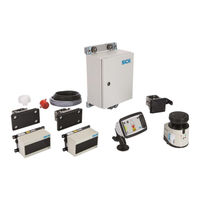
SICK LMS151 RDW Operating Instructions Manual (90 pages)
Driver assistance system
Brand:
SICK
| Category:
Industrial Equipment
| Size: 5 MB
Table of Contents
Table of Contents
3
1 About These Operating Instructions
6
Function of this Document
6
Target Group
6
Information Depth
6
Abbreviations Used
7
Symbols Used
7
2 Safety
8
Qualified Safety Personnel
8
Applications of the System
8
Intended Use
9
General Safety Notes and Protective Measures
9
Safety Notes and Symbols
9
General Safety Notes
10
Potential Sources of Danger
11
Protection of the Environment
13
Power Consumption
13
Disposal after Final Decommissioning
13
3 Product Description
14
Scope of Delivery
14
System Components
14
Fig. 1: Scope of Delivery for TPS
14
Fig. 2: Laser Output Aperture of the LD-MRS Front and Rear
15
Fig. 3: Laser Output Aperture of the LMS151 RDW
15
Fig. 4: Operator Display with Mounting Kit
15
Fig. 5: Control Cabinet
16
Fig. 6: Tone Buzzer
16
Fig. 7: GPS Receiver
16
System Functionality
17
Front Collision Warning
17
Fig. 8: Mounting Kit for LMS151 RDW and LD-MRS Front and Rear
17
Fig. 9: Front Collision Warning
17
Rear End Collision Warning
18
Road Departure Warning
18
Fig. 10: Rear End Collision Warning
18
Fig. 11: Road Departure Warning Function with In-Lane Symbol
18
Black Spot Warning
19
Fig. 12: Black Spot Warning
19
Status Indicators
20
Fig. 13: Status Indicators for the LMS511
20
Fig. 14: the Operator Display in Configuration and Operating Mode
21
Fig. 15: DIP Switch on the Tone Buzzer
21
4 Mounting
22
Function Test before Mounting
22
Mounting the Lidar Sensor
22
Fig. 16: Mounting the LD-MRS Using Mounting Kit with Shock Absorber
23
Fig. 17: Mounting the LMS151 RDW Using Mounting Kit with Shock Absorber
23
Fig. 18: Mounting Position of the LD-MRS HD Front
24
Fig. 19: Mounting Position of the LD-MRS HD Rear
24
Mounting the Bracket for the Operator Display
25
Fig. 20: Mounting Position of the LMS151 RDW
25
Fig. 21: Mounting the Operator Display
25
Mount the Control Cabinet
26
Fig. 22: Mounting the Control Cabinet
26
Mount the GPS Receiver
27
Mounting the Tone Buzzer
27
Fig. 23: Mounting the GPS Receiver
27
Fig. 24: Mounting the Tone Buzzer
27
5 Electrical Installation
28
Wiring Plan
28
Fig. 25: TPS Wiring Plan
28
Fig. 26: TPS Wiring Connection Overview (Inside Control Cabinet)
29
Connecting the LD-MRS Front and Rear Lidar Sensor
30
Fig. 27: LD-MRS Connections
30
Fig. 28: Connecting the LD-MRS to the Control Cabinet
30
Connecting the LMS151 RDW Lidar Sensor
31
Fig. 29: Connecting the LMS511 to the Ethernet Switch
31
Fig. 30: LMS151 Connections
31
Fig. 31: Connecting the LD-MRS to the Control Cabinet
32
Fig. 32: Connecting the LMS511 to the Ethernet Switch
32
Connecting the Operator Display
33
Fig. 33: Connecting the Operator Display
33
Fig. 34: Connecting the Operator Display to the Control Cabinet
33
Fig. 35: Inserting Connecting Cables on the Operator Display
34
Fig. 36: Mounting the Adapter on the Operator Display
34
Fig. 37: Mounting the Adapter with the Operator Display on the Bracket
35
Connecting the GPS Receiver
36
Connecting the Tone Buzzer
36
Fig. 38: Connecting the Operator Display
36
Fig. 39: Connecting the Tone Buzzer
36
Connecting the Control Cabinet
37
Fig. 40: Connecting the Control Cabinet to the Voltage Supply of the Truck
37
Connecting the Reverse Signal (Optional)
38
Connecting the Pause Signal
38
Fig. 41: Connecting the Control Cabinet to the Voltage Supply of the Truck
38
Connecting the RDW Lights (Optional)
39
Fig. 42: Connecting the Control Cabinet to the RDW Lights (Optional)
39
6 Commissioning
40
Launching the System
40
Fig. 43: Self-Test of the System on the Operator Display
40
Fig. 44: Information about Incomplete Configuration
40
Fig. 45: Configuration Mode after Launching for the First Time
41
Fig. 46: Testing Operational Readiness of the Devices
41
The Operator Display in Configuration Mode
42
Making Vehicle Setup Settings
43
Configuring the Lidar Sensors
44
Starting Sensor Setup
44
Front Sensor Set up
45
Rear Sensor Set up
46
RDW Sensor Set up
48
Saving Sensor Setup Settings
50
Making Supervisor Setup Settings
51
Front Zones Set up
51
RDW Setup
53
Saving Sensor Setup Settings
54
Reverse Gear and Components Connection Check
54
Switch to the Operating Mode
55
Quit Configuration Mode
55
Operating Mode for Person Carrying out Commissioning
55
Enable Operating Mode for Truck Operators
57
7 Operation
58
Start the Truck and System
58
The Operator Display in the Operating Mode for Truck Drivers
59
Forward Driving
59
Black Spot Warning
60
Reverse Driving
60
Operate the System
61
Switching between Day/Night Mode
61
Collision Warning in the Event of Obstacles in the Warning Zone
62
Collision Warning in the Event of Unintentional Road Departure
63
React to Collision Awareness
63
8 Maintenance
64
Overview of Maintenance Tasks
64
Maintenance During Operation
64
Cleaning the Lidar Sensor
64
Fig. 47: Cleaning the Lidar Sensor
64
Visual Inspection of the Cables
65
Replacing Components
65
Replacing a Lidar Sensor
66
Replacing the Operator Display
67
Fig. 48: Removing the Operator Display from the Bracket
67
Fig. 49: Removing the Adapter from the Operator Display
67
Activities on the Web Interface
68
Calling up the Web Interface
68
Fig. 50: the Web Interface
68
Enable Configuration Mode on the Display
69
Activating Operating Mode for Truck Operators Via the Web Interface
70
Up- and Downloading of GPS Black Spots
70
Updating TPS Software
71
9 Fault Diagnosis
72
Response to Faults
72
Fault Indicators of the LMS151
72
Typical Fault Situations During Commissioning
73
Configuration Incomplete or Incorrect
73
Lidar Sensor Not Available
73
Typical Fault Situations During Operation
74
Viewing Window of the Lidar Sensor Contaminated
74
Lidar Sensor Not Available
75
No Image on Display
76
SICK Support
76
10 Annex
77
10.1 Technical Data
77
10.2 Dimensional Drawings
78
10.2.1 Dimensional Drawing of the 3D Lidar Sensor LD-MRS
78
10.2.2 Dimensional Drawing of the 2D Lidar Sensor LMS151
78
Fig. 51: Dimensional Drawings of the LD-MRS 3D Lidar Sensor
78
Fig. 52: Dimensional Drawings of the LMS151 2D Lidar Sensor
78
10.2.3 Display Dimensional Drawing
79
Fig. 53: Dimensional Drawings of the Operator Display
79
10.2.4 Control Cabinet Dimensional Drawing
80
10.2.5 Tone Buzzer Dimensional Drawing
80
Fig. 54: Dimensional Drawings of the Mounting Kit for the Operator Display
80
Fig. 55: Dimensional Drawings of Control Cabinet
80
Fig. 56: Dimensional Drawing of the Tone Buzzer
80
10.3 Tone Selection for Tone Buzzer
81
Fig. 57: Tone Selection for Tone Buzzer
81
11 Figures and Tables
82
List of Tables
82
Figures and Tables
83
List of Figures
83
Keywords Index
85
Advertisement
Advertisement
Related Products
SICK LD-MRS HD
SICK LXRH
SICK LXRC
SICK LMS151
SICK LMS153
SICK LMS133
SICK LMS1 Series
SICK 1036556
SICK 1036557
SICK 1036558
SICK Categories
Accessories
Security Sensors
Measuring Instruments
Scanner
Barcode Reader
More SICK Manuals
Login
Sign In
OR
Sign in with Facebook
Sign in with Google
Upload manual
Upload from disk
Upload from URL