Table of Contents
Advertisement
Quick Links
Advertisement
Table of Contents

Subscribe to Our Youtube Channel
Related Manuals for GSS PHIS 1000 S


Summary of Contents for GSS PHIS 1000 S
- Page 1 PHIS 1000 S...
-
Page 2: Table Of Contents
o n t e n t s 1 Safety regulations and notes ................ 4 2 General information ..................5 Packing contents ................5 Meaning of the symbols used ............5 Technical data ................5 Description ...................6 Software query................7 3 Assembly ....................8 Installing the cassette..............8 EMC regulations ................9 Cassette overview................10 Connecting the cassette ..............10 Retrofitting a CA module ..............11... - Page 3 Setting the DVB mode ..............30 Setting the input frequency ............30 Setting the output parameters ............32 Setting the IP addresses for the outputs ...........33 Switching the IP address off or on ..........34 Selecting the transmission protocol ..........34 Setting the port number ..............34 Defining the quantity of data packets ..........35 Setting the forward error correction ..........35 Setting the transmission channel ............35...
-
Page 4: Safety Regulations And Notes
a f e t y r e g u l a t i o n s a n d n o t e s • Assembly, installation and servicing should be carried out by authorised electricians. • Switch off the operating voltage of the system before beginning with assem- bly or service work or pull out the mains plug. -
Page 5: General Information
2.1 P aC k i n g C o n t e n t s 1 Cassette PHIS 1000 S 2 RF cables 1 LAN cable 2 F jack-to-jack adapter... -
Page 6: Description
Connections SAT inputs: ................2 F sockets RF output: ............1 IEC socket (no function) LAN: ................1 RJ 45 socket Connection strip (10-pin): ....for supply voltages and control circuits RS 232 socket: ........serial interface for software update Conditional access:......several channels can be descrambled. 2.4 d es C r i P t i o n The cassette is a DVB-S2 / SPTS converter which combines modulated services... -
Page 7: Software Query
A control voltage for a DiSEqC controlled multi switch which is not suitable as power supply is present at the antenna input (use an external power sup- ply). The cassette is controlled with the head-end station control unit as well as with station tables which can be uploaded and stored to the cassettes via Ethernet. -
Page 8: Assembly
s s e m b l y 3.1 i n s ta l l i n g t h e C a s s e t t e – Ensure the head-end station is mounted so it will not be able to vibrate. Avoid, for example, mounting the head-end station onto a lift shaft or any other wall or floor construction that vibrates in a similar way. -
Page 9: Emc Regulations
3.2 emC r e g u l at i o n s To comply with the current EMC regulations, it is necessary to connect the lines leading in and out of the head-end station using cable terminals. When mounting the cassette in a head-end station which is installed in a 19" cabinet, make sure the connections leading in and out for the 19" cabinet are made using cable terminals. The attenuation of shielding of the connection lines for ASI and antenna must meet the requirements for "Class A". CLASS • Insert the required number of cable terminals in the openings provided in the head-end station or in the 19" cabinet. Tighten the nuts on the cable terminals until the teeth on the lock washer have penetrated the exterior coating and a good connection is made between the hous- ing and cable terminals. -
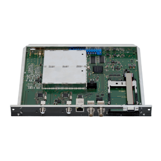
Page 10: Cassette Overview
3.3 C a s s e t t e ov e rv i e w Status LED of channel strip "B" SAT IF input of channel strip "B" Status LED of channel strip "A" SAT IF input of channel strip "A" Status LED of the LAN interface (data transfer) LAN socket Status LED of the LAN interface (network connection) -
Page 11: Retrofitting A Ca Module
3.5 r Ca e t r o f i t t i n g m o d u l e The cassette is equipped with a common interface. It allows you to connect a CA module for various scrambling systems and service providers. Scrambled channels can only be descrambled with a CA module suitable for the scram- bling system and the corresponding smart card. -
Page 12: The Control Panel At A Glance
C o n t r o l P a n e l g l a n C e 4.1 m e n u i t e m s Programme the cassette using the buttons on the control unit of the head-end station. -
Page 13: Programming
The switchover of the different station tables is done via the menu "LOCATION" in the PHIS 1000 S cassettes. This menu only appears if station tables were up- loaded before. The menus "INPUT" and "IP-OUT" then are hidden. In point 5.3 the structure of a corresponding text file and in point 5.4 the pro- gramming of the cassettes (upload) is described. -
Page 14: Programming Procedure
5.2 P ro g r a m m i n g Pro C e d u r e Ein / On Bedienhinweise Operating Hints BE–Remote V 45 "blättert" Menüs vorwärts. scrolls forward through the menu. please wait … "blättert" Menüs rückwärts. scrolls backward through the menu. - Page 15 Tuner B off/– –Hh …DFV1 *DiSEqC is a trademark of EUTELSAT 10600 / 9750 ◀ ▶ ◀ ▶ Bx 4A SYMBOL DVB-S / QPSK… / 8PSK… / DTV… 27500 DVB-S 27500 / 22000 Bx 4A FREQ ◀ ▶ 11836 -1.8 CN 12 Kanalzug “A”...
- Page 16 1 … 7 copy ◀ ▶ IP 1 DATARATE auto 2 … 80.0 MBits ( 7.3) > 10.0 MB IP 1 001/016 Das Erste IP 1 AUDIO all / 01/… IP 1 PIDS auto manual/auto manual manual Nur wenn "PIDS" –> "manual" Only if "PIDS"...
-
Page 17: Creating Station Tables
The head-end station can be pre-programmed with different station allocations via the station tables. Then the configuration can be switched over by the menu "Location" of the cassette PHIS 1000 S. The station tables are created using a text editor and stored e.g with the title "config.txt"... -
Page 18: The Structure Of The Text File For Programming Station Tables
P r o g r a m m i n g s tat i o n ta b l e s —> Programming for the receiving cassette PHIS 1000 S L "Name 1" Identifier for "Location" "Name 1" arbitrary title, this title is shown in menu "Location" for select- ing the configuration. - Page 19 T 1,11836,H,27500 // ARD transponder Identifier for transponder Selection of the "SAT configuration" 1,D1,9750,10600) Commas are the separators between the items 11836 Downlink frequency Polarity - H, L 27500 Symbol rate // ARD… Comment; following the "double slash" comments can be en- tered. —> With this sequence the LNB settings of one tuner of one cassette are predefined.
- Page 20 Possible Flags are: —> AC3 tone NOAC3 —> No AC3 tone —> Teletext —> DVB subtitle —> Event Information Table, included information about the service (e.g. start time, duration, scrambling etc.). NONE —> suppresses other PIDs —> passes through all PIDs —>...
- Page 21 —> With this sequence the settings of one modulator of one cassette are predefined. The order of the cassettes is defined by the order of the hardware IP addresses which are assigned to the cassettes manually. Modulator A transmitting cassette 1, modulator B transmitting cassette 1, modulator A transmitting cassette 2, modulator B transmitting cassette 2, etc.
-
Page 22: Uploading The Station Tables To The Cassettes
5.4 u P loa d i n g t h e s tat i o n ta b l es t h e C a s s e t t e s To upload the station tables to the cassettes the software "HotelTransponder. exe"... -
Page 23: Programming The Cassette
5.5 P r o g r a m m i n g t h e C a s s e t t e —> Pressing the button for longer than 2 seconds cancels the programming procedure. This takes you back to the program item "Selecting the cassette"... -
Page 24: Selecting The Station Table
• Press the button. —> The "Selecting the station table" – "LOCATION" ("virtual station ta- bles" is activated) or "Setting the Ethernet parameters" – "ETHERNET" ("virtual station tables" is not activated) menu is activated. e l e C t i n g t h e s tat i o n ta b l e... -
Page 25: Setting The Hardware Ip Address Of The Cassette
• Press the button to activate the setting options ("Options"). —> The "Setting the hardware IP address of the cassette" – menu "IP-ADDR" is activated. iP e t t i n g t h e h a r dwa r e a d d r es s t h e C a s s e t t e... -
Page 26: Setting The Address Range
e t t i n g t h e a d d r es s r a n g e In this menu you define the address range for the cassettes connected to the LAN network. Bx 4 IP-MASK 255.255.255. •... -
Page 27: Setting The Udp Port
udP e t t i n g t h e P o r t The UDP port setting is required if the text file with the station tables can not be uploaded via port 60000 (default). The port set must match to the port for uploading the text file (page 18). -
Page 28: Lnb Oscillator Frequency / Control Voltage
—> The "Setting the LNB oscillator frequency" – "LNB" menu is acti- vated. lnb os C i l l ato r f r e q u e n C y C o n t r o l vo ltag e In this menu set the oscillator frequency of the LNB used and, if necessary, a LNB control voltage. -
Page 29: Setting The Input Symbol Rate
—> The control voltage only serves to control multiswitches and is not suitable for power supply of upstreamed components (maximum load 65mA). —> GSS Multiswitches must be triggered by the following DiSEqC comands: Input group A —> DiSEqC command D0 Input group B —> DiSEqC command D1 Input group C —> DiSEqC command D2 Input group D —>... -
Page 30: Setting The Dvb Mode
dvb e t t i n g t h e m o d e The cassette recognizes the transmitted DVB mode and switches over between the normal QPSK mode (DVB-S) and the DVB-S2 mode. Receiving stations with DVB-S2 mode, we suggest to preset the DVB mode to shorten the time for searching stations. - Page 31 —> The "CN 12" display indicates the signal to noise ratio of the signal received. —> The quality of the received transport stream (level and C/N) is indi- cated by a status LED. —> If the LED lights yellow the SAT IF input level and the signal to noise ratio must be tested.
-
Page 32: Setting The Output Parameters
e t t i n g t h e o u t P u t Pa r a m e t e rs In this menu you select the IP output, for which you would like to set the output parameters in the submenus. -
Page 33: Setting The Ip Addresses For The Outputs
iP e t t i n g t h e a d d r es s es f o r t h e o u t P u t s In this menu you set the IP address for the IP output selected. —> "IPTV" IP addresses (menu IP-OUT), which are used to send and re- ceive the IPTV channels (e.g. 227.40.50.x) must be within the "mul- ticast" range from 224.5.0.0 to 231.255.255.255. -
Page 34: Switching The Ip Address Off Or On
iP w i tC h i n g t h e a d d r es s o f f e l e C t i n g t h e t r a n s m i s s i o n P r oto C o l e t t i n g t h e... -
Page 35: Defining The Quantity Of Data Packets
• Press the button. —> The "Defining the quantity of data packets, setting the forward error correction, setting the transmission channel" – "PKTS / FEC" menu is activated. e f i n i n g t h e q ua n t i t y data PaC k e t s e t t i n g... -
Page 36: Setting The Output Data Rate
Copying the settings to all IP outputs • Pressing the button the settings "Quantity of the data packets", Forward error correction" and "Transmission channel" can be copied to all IP outputs. copy —> The display shows " " for a short time. •... -
Page 37: Allocating Services Manually
l lo C at i n g s e rv i C es m a n ua l ly In this menu all services (programmes) supplied via "Tuner A" and "Tuner B" can be displayed and each service is assigned a set IP address in the "OUT-IP" menu. -
Page 38: Selecting The Sound Options Of The Service
If no service is found the display shows "– – –" instead of the name of the service. In this case check the configuration of the antenna system including the head-end station and the previous settings of the cassette. • Press the button. -
Page 39: Switching Dvb Service Information On Or Off
Setting "auto" Return to the "Setting the output parameters" – "IP-OUT 1" menu (page 32). dvb w i tC h i n g s e rv i C e i n f o r m at i o n o f f —>... -
Page 40: Stuffing The Output Data Rate
t u f f i n g t h e o u t P u t data r at e In this menu it is to set, whether the current output data rate remains "unmodi- fied" or whether it is stuffed to a "constant" value. This value is a little bit higher than the current "maximum"... -
Page 41: Factory Reset
aC to ry r es e t In this menu you can reset all settings to the factory defaults. Bx 4 FACTORY Bx 4 FACTORY ▶ Defaults => STORE => M • Press the button. —> The submenu "FACTORY STORE" is invoked. —>... -
Page 42: Operation With A Ca Module
Ca P e r at i o n w i t h m o d u l e Scrambled channels can only be descrambled with a CA module suitable for the scrambling system and the corresponding smart card. The smart card con- tains all the information for authorisation, descrambling and subscription. - Page 43 • Press the button to activate the menu of the CA module. —> The display shows e.g.: Bx 4A 01/03 MENU Information Meaning of the indicators: "01/03" – The first of three menu items is activated. "MENU" – The menu of the CA module is activated. For the explanation of further details please use the operating instructions of the CA module used.
-
Page 44: Descrambling Services
es C r a m b l i n g s e rv i C es In this menu you select the services wished from the scrambled data stream, which are to be descrambled. —> The display shows e.g.: Bx 4A TV X 04/09 .. -
Page 45: Final Procedures
Save changes and activate the filter: • Press the button. —> The filter is activated. The display shows the "Configuring the CA module" – "CA" menu. Bx 4A Menu <= => Edit • Press the button. —> The "Selecting the input data stream" – "INPUT" menu is activated (page 27). - Page 46 Phone: +49 (0) 911 / 703 8877 • Fax: +49 (0) 911 / 703 9210 www.gss.de/en • info@gss.de CLASS CLASS Service: Phone: +49 (0) 911/703 2221; Fax: +49 (0) 911/703 2326; service@gss.de Alterations reserved. Technical data E. & O.E. © by GSS Grundig Systems GmbH V5/001/2017...
Need help?
Do you have a question about the PHIS 1000 S and is the answer not in the manual?
Questions and answers