Table of Contents
Advertisement
Quick Links
Advertisement
Table of Contents

Related Manuals for GSS PHDQ 8008 TSR


Summary of Contents for GSS PHDQ 8008 TSR
- Page 1 PHDQ 8008 TSR...
-
Page 2: Table Of Contents
o n t e n t s 1 Safety regulations and notes ................ 4 2 General information ..................5 Packing contents ................5 Meaning of the symbols used ............5 Technical data ................5 Description ...................6 Input signal path ................6 Output signal path "OUTROUTE" ............7 Menu setting "ASI => ASI" ............7 Menu setting "1 =>... - Page 3 Input symbol rate .................22 DVB mode ..................22 Input frequency ................23 Signal to noise ratio ..............23 Setting the PSI ................24 QAM modulation ................25 Inverting the user signal ..............25 Stuffing..................26 Setting a substitute signal ..............27 Factory reset / Cassette reset ............28 Factory reset ................28 Cassette reset (Restart) ............29 Saving settings ................29...
-
Page 4: Safety Regulations And Notes
a f e t y r e g u l a t i o n s a n d n o t e s • Assembly, installation and servicing should be carried out by authorised electricians. • Switch off the operating voltage of the system before beginning with assem- bly or service work or pull out the mains plug. -
Page 5: General Information
2.1 P aC k i n g C o n t e n t s 1 Cassette PHDQ 8008 TSR 2 RF cables 1 Brief assembly instructions 1 Measuring log 2.2 m... -
Page 6: Description
Connections SAT inputs: ................2 F sockets RF output: ................1 IEC socket ASI input: ..............1 BNC socket, 75 Ω ASI output: ..............1 BNC socket, 75 Ω Connection strip (10-pin): ....for supply voltages and control circuits RS 232 socket: ........serial interface for software update 2.4 d es C r i P t i o n The twin transmodulator cassette is a QPSK-converter, which converts all sta-... - Page 7 "outroute" u t P u t s i g n a l Pat h "asi => asi" e n u s e t t i n g Transport stream 1 is made available via modulator "A", transport stream 2 via modulator "B" and the transport stream ASI from the ASI input via the ASI output.
-
Page 8: General
e n e r a l Using the software PSW 1000 the transport streams of the cassette can be processed. This means that the data (PSI, NIT, SI etc.) primary contained in the transport stream can be replaced by the data processed with the software PSW 1000. -
Page 9: Assembly
s s e m b l y 3.1 i n s ta l l i n g t h e C a s s e t t e – Ensure the head-end station is mounted so it will not be able to vibrate. Avoid, for example, mounting the head-end station onto a lift shaft or any other wall or floor construction that vibrates in a similar way. - Page 10 3.2 emC r e g u l at i o n s To comply with the current EMC regulations, it is necessary to connect the lines leading in and out of the head-end station using cable terminals. When mounting the cassette in a head-end station which is installed in a 19" cabinet, make sure the connections leading in and out for the 19" cabinet are made using cable terminals. The attenuation of shielding of the connection lines must meet the requirements for "Class A". CLASS • Insert the required number of cable terminals in the openings provided in the head-end station or in the 19" cabinet. —>...
-
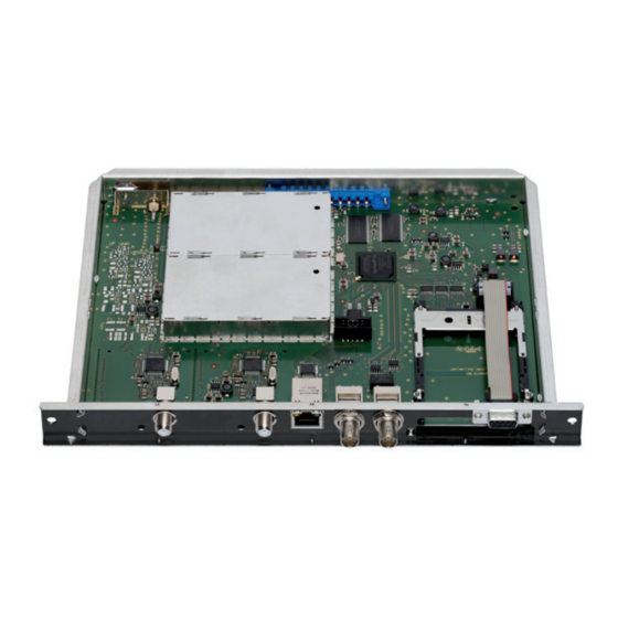
Page 11: Cassette Overview
3.3 C a s s e t t e ov e rv i e w D-SUB socket "RS 232" without function ASI output ASI input without function SAT input (tuner "A") Status LED of channel strip "A" SAT input (tuner "B") Status LED of channel strip "B"... -
Page 12: Menu Items
C o n t r o l P a n e l g l a n C e 4.1 m e n u i t e m s Program the cassette using the buttons on the control unit of the head-end sta- tion. - Page 13 r o g r a m m i n g 5.1 P r e Pa r at i o n • Connect the test receiver to the RF output or the test output of the head-end station. • Set the output channel / output frequency of the cassette (see page 19) and adjust the TV test receiver to this channel.
- Page 14 5.3 P ro g r a m m i n g Pro C e d u r e Bedienhinweise Operating Hints BE–Remote V 45 Ein / On "blättert" Menüs vorwärts. scrolls forward through the menu. please wait … "blättert" Menüs rückwärts. scrolls backward through the menu.
- Page 15 10600 MHz 4A/B SYMBOL ◀ ◀ ▶ ▶ 27500 DVB-S DVB-S / DVB-S 2 … 4A/B FREQ 4A/B ◀ ▶ Anzeige: Signalqualität Display: Signal quality 11835 -0.7 CN 15 15.3 dB (+ 11.3) OK 4A/B 4A/B ◀ ▶ normal / inverse 256-QAM normal 4 …...
- Page 16 5.4 P r o g r a m m i n g t h e C a s s e t t e —> Pressing the button for longer than 2 seconds cancels the programming procedure. This takes you back to the programme item "Selecting the cassette"...
- Page 17 u t P u t s i g n a l Pat h In this menu you define the signal path of the output transport streams. Menu setting "ASI => ASI" (page 7). Menu setting "1 => ASI ASI => MA" (page 7). Menu setting "2 => ASI ASI => MB" (page 7). Bx 4 OUTROUTE ASI=>ASI...
- Page 18 asi e t t i n g t h e o P t i o n s In this menu you define the size of the data packets, their polarity and the type of transmission. For this setting please take the required information from the documentation (technical data) of the ASI component to be connected.
- Page 19 e l e C t i n g t h e C h a n n e l s t r i P Bx 4 LINE Line A <= => Line B • By pressing select channel strip "A" ("Line A") or channel strip "B" ("Line B") by pressing the button.
- Page 20 e t t i n g t h e o u t P u t C h a n n e l In this menu you set the output channel of the channel strip. Additionally the modulator of the channel strip can be switched off or on. Bx 4A OUTPUT •...
- Page 21 dj u s t i n g t h e o u t P u t l e v e l s t h e C h a n n e l s t r i P s This menu item is used to set the output levels of the modulators of the channel strips "A"...
- Page 22 n P u t s ym b o l r at e dvb m o d e The symbol rates of the satellite transponders can be found in the current chan- nel table of the satellite operator, in various satellite magazines and in the Internet.
- Page 23 n P u t f r e q u e n C y If three dots " … " appear in the second line of the display, the cassette is in the "station search" mode. Please wait until the process has finished. Bx 4A FREQ Bx 4A...
- Page 24 If "OK" is shown, the signal to noise ratio is ok. If a value < 5 is shown under the display changes from "OK" to "??". In this case test the input signal. —> In addition to the indicator in the display, there is also a status LED which indicates the quality of the received transport stream: Status LED Tuner A Status LED Tuner B...
-
Page 25: Inverting The User Signal
Setting "MIX+TABLES+EIT": In addition to the functions of the "MIX+TABLES" setting the EIT is levelled. Bx 4A • Press to select the operating mode. • Press the button. —> The "QAM modulation" – " " menu is activated. qam m o d u l at i o n n v e r t i n g t h e u s e r... -
Page 26: Stuffing
t u f f i n g Bx 4A STUFFING SR=6900 (6325) Number 1 Number 2 SR=6900 (= "Number 1"): Active output symbol rate (6325) (= "Number 2"): Current measured output symbol rate. —> This value must be less than the value of "Number 1". If necessary remove stations using the software PSW 1000 or increase the value of "Number 1". - Page 27 Is the "Number 1" lower than "Number 2" question marks "??" appear in the display. In this case transmission problems may occur. Bx 4A STUFFING 6200 (6325) ?? • Press the button. —> The "Setting a substitute signal in the case of an incorrect input FAILURE signal"...
- Page 28 / C aC to ry r es e t a s s e t t e r es e t In this menu, you can reset all settings to the factory defaults or call up a menu to reset the cassette (restart). Bx 4 FACTORY Bx 4...
- Page 29 a s s e t t e r es e t es ta r t Bx 4 FACTORY Defaults => • Press the button. Bx 4 FACTORY STORE => M • Press the button. Bx 4 RESET RESET => M —>...
- Page 30 h a n n e l a n d f r e q u e n C y t a b l e s Advice for a frequency raster (8 MHz) in the Band I/III 42.00 82.00 146.00 186.00 226.00 266.00 50.00 114.00...
- Page 31 Phone: +49 (0) 911 / 703 8877 • Fax: +49 (0) 911 / 703 9210 www.gss.de/en • info@gss.de CLASS CLASS Service: Phone: +49 (0) 911/703 2221; Fax: +49 (0) 911/703 2326; service@gss.de Alterations reserved. Technical data E. & O.E. © by GSS Grundig Systems GmbH V40/001/2018...
Need help?
Do you have a question about the PHDQ 8008 TSR and is the answer not in the manual?
Questions and answers