
Related Manuals for SEW-Eurodrive MOVI-PLC basic DHP11B-T0


Summary of Contents for SEW-Eurodrive MOVI-PLC basic DHP11B-T0
- Page 1 Gearmotors \ Industrial Gear Units \ Drive Electronics \ Drive Automation \ Services ® MOVI-PLC basic DHP11B.. Controller FA37A100 Edition 06/2006 anual 11427426 / EN...
- Page 2 SEW-EURODRIVE – Driving the world...
-
Page 3: Table Of Contents
Contents 1 Important Notes...................... 5 2 Introduction ......................6 ® MOVI-PLC – Comprehensive, Scalable, Powerful........6 ® MOVI-PLC basic DHP11B.. controller ............7 OST11B option .................... 11 3 Assembly / Installation Instructions..............12 ® Mounting options for the MOVI-PLC basic DHP11B.. controller....12 ®... - Page 4 Contents 6 PROFIBUS-DP-V1 Functions................58 Introduction to PROFIBUS-DP-V1 ............... 58 Features of the SEW-DP-V1 interfaces ............60 Structure of the DP-V1 parameter channel ..........61 Project planning for a C1 master..............74 Appendix ...................... 74 7 Error Diagnostics ....................76 Diagnostic procedure for system buses CAN 1 / CAN 2......
-
Page 5: Important Notes
Important Notes Important Notes • This manual does not replace the detailed operating instructions! • Only trained personnel are allowed to perform installation and startup ® observing valid accident prevention regulations and the MOVIDRIVE ® ® MDX60B/61B, MOVITRAC B or MOVIAXIS operating instructions! Documentation •... -
Page 6: Introduction
Introduction MOVI-PLC® – Comprehensive, Scalable, Powerful Introduction Content of the This user manual describes: manual ® ® • How to install the MOVI-PLC basic DHP11B.. controller in MOVIDRIVE MDX61B • Assembly and installation of the OST11B option ® • Interfaces and LEDs of the MOVI-PLC basic DHP11B.. - Page 7 Introduction MOVI-PLC® basic DHP11B.. controller ® Control class • MOVI-PLC basic DHP11B.. allows coordinated single axis movements and integra- tion of external inputs / outputs as well as Drive Operator Panels (DOP). This makes ® MOVI-PLC basic DHP11B.. suitable for the task of module controller and also for that of stand-alone controller for machines of medium complexity.
- Page 8 Introduction MOVI-PLC® basic DHP11B.. controller Automation Use as a stand-alone machine controller topologies ® You can also use the MOVI-PLC basic DHP11B.. controller as a control unit for an entire machine. ® If used without a higher-level PLC, the MOVI-PLC basic DHP11B..
- Page 9 Introduction MOVI-PLC® basic DHP11B.. controller Use as a module controller ® You can also use the MOVI-PLC basic DHP11B.. controller for decentralized automa- ® tion of a machine module ( Æ Following figure). In this way, the MOVI-PLC basic DHP11B.. controller coordinates motion sequences in the axis system. The control card is connected to a higher-level PLC via the PROFIBUS interface.
- Page 10 Introduction MOVI-PLC® basic DHP11B.. controller ® System buses You can use the MOVI-PLC basic DHP11B.. controller to control a machine module by ® CAN 1 and CAN 2 coupling several inverters via the system bus. The MOVI-PLC basic DHP11B.. controller controls all the drives in the machine module and thereby relieves the higher- level control (e.g.
-
Page 11: Ost11B Option
Introduction OST11B option Binary inputs and Binary inputs and outputs enable you to switch actuators, (e.g. valves) and evaluate outputs binary input signals (e.g. sensors). You can freely use the binary inputs and outputs in ® the PLC Editor of the MOVITOOLS MotionStudio software in programming. -
Page 12: Assembly / Installation Instructions
Assembly / Installation Instructions Mounting options for the MOVI-PLC® basic DHP11B.. controller Assembly / Installation Instructions ® Mounting options for the MOVI-PLC basic DHP11B.. controller Observe the following installation instructions: ® ® • You can plug the MOVI-PLC basic DHP11B.. controller into the MOVIDRIVE ®... -
Page 13: Installing Movi-Plc® Basic Dhp11B.. In Movidrive® Mdx61B
Assembly / Installation Instructions Installing MOVI-PLC® basic DHP11B.. in MOVIDRIVE® MDX61B ® Basic procedure for installing or removing an option card in MOVIDRIVE MDX61B 53001AXX 1. Remove the retaining screws holding the card retaining bracket. Pull the card retaining bracket out evenly from the slot (do not twist!). 2. -
Page 14: Installation Of Ost11B Option In Movidrive
Assembly / Installation Instructions Installation of OST11B option in MOVIDRIVE® MDX61B ® Installation of OST11B option in MOVIDRIVE MDX61B ® Installation • If the MOVI-PLC basic DHP11B.. controller is installed in the fieldbus slot [2], you options must install the OST11B option in the encoder slot [1]. Observe the instructions in ®... -
Page 15: Installation Of Movi-Plc ® Basic Dhp11B
Assembly / Installation Instructions Installation of MOVI-PLC® basic DHP11B.. controller ® Installation of MOVI-PLC basic DHP11B.. controller 3.4.1 Functional description of the terminals, DIP switches and LED Front view ® MOVI-PLC basic Designation DIP switches Function DHP11B.. controller Terminal LED 1 24V / I/O OK Status of voltage supply I/O LED 2... -
Page 16: Connecting Binary Inputs And Outputs (Connector X31)
Assembly / Installation Instructions Installation of MOVI-PLC® basic DHP11B.. controller 3.4.2 Connecting binary inputs and outputs (connector X31) Connector X31 provides eight binary inputs or outputs (e.g. for controlling external actu- ators / sensors). ® You can program the binary inputs / outputs in the PLC Editor of the MOVITOOLS MotionStudio software. -
Page 17: Connection Can 2 System Bus (Connector X32) / Can 1 (Connector X33)
Assembly / Installation Instructions Installation of MOVI-PLC® basic DHP11B.. controller 3.4.3 Connection CAN 2 system bus (connector X32) / CAN 1 (connector X33) Do not connect more than 64 units to the CAN 2 or CAN 1 system bus. The system bus supports the address range 0 ... -
Page 18: Movidrive
Assembly / Installation Instructions Installation of MOVI-PLC® basic DHP11B.. controller Cable length • The permitted total cable length depends on the baud rate setting of the system bus: – 125 kBaud 320 m Æ – 250 kbaud 160 m Æ –... - Page 19 Assembly / Installation Instructions Installation of MOVI-PLC® basic DHP11B.. controller The PROFIBUS interface sends a TTL control signal for a repeater or fiber optic adapter (reference = pin 9) via pin 4 (CNTR-P). ® Baud rates The operation of the MOVI-PLC basic DHP11B..
-
Page 20: Connecting Rs485 Interface Com 1 (Connector X34)
Assembly / Installation Instructions Installation of MOVI-PLC® basic DHP11B.. controller 3.4.5 Connecting RS485 interface COM 1 (connector X34) You can connect one of the following devices to the RS485 interface COM 1: • Engineering PC (Æ Sec. 3.8) or • DOP11A operator terminal DHP11B PC COM... -
Page 21: Operating Displays Of The Movi-Plc
Assembly / Installation Instructions Installation of MOVI-PLC® basic DHP11B.. controller ® 3.4.6 Operating displays of the MOVI-PLC basic DHP11B.. controller ® The MOVI-PLC basic DHP11B.. controller comes equipped with seven LEDs that indi- ® cate the current status of the MOVI-PLC basic DHP11B.. - Page 22 Assembly / Installation Instructions Installation of MOVI-PLC® basic DHP11B.. controller ® PLC status LED The PLC status LED indicates the firmware status of the MOVI-PLC basic DHP11B.. controller. Diagnostics Remedy status ® Flashing • Firmware of the MOVI-PLC basic – green DHP11B..
- Page 23 Assembly / Installation Instructions Installation of MOVI-PLC® basic DHP11B.. controller CAN 2 status LED The CAN 2 status LED indicates the status of the CAN 2 system bus. CAN 2 Diagnostics Remedy status Orange • The CAN 2 system bus is being initialized. – Green •...
-
Page 24: Installation Of Ost11B Option
Assembly / Installation Instructions Installation of OST11B option Installation of OST11B option 3.5.1 Description of terminal and LED functions Front view Designation Function OST11B option Terminal Connector X35: X35:4 BZG_COM 2 Reference potential COM2 RS485 COM 2 X35:3 RS– Signal RS485– (RJ10 socket) X35:2 Signal RS485+... -
Page 25: Ost11B Option Operating Display
Assembly / Installation Instructions Installation of OST11B option 3.5.3 OST11B option operating display ® CTRL LED The CTRL LED indicates correct communication with the MOVI-PLC basic DHP11B.. controller. CTRL Diagnostics Remedy Green • Communication between OST11B option – ® and the MOVI-PLC basic DHP11B.. -
Page 26: Moviaxis
Assembly / Installation Instructions Installation of MOVI-PLC® basic DHP11B.. controller in MOVIDRIVE® ® ® Installation of MOVI-PLC basic DHP11B.. controller in MOVIDRIVE MDX61B ® MOVI-PLC basic DHP11B.. controller is installed as stipulated in section 3.4. The ® ® MOVI-PLC basic DHP11B.. controller is supplied with voltage by MOVIDRIVE MDX61B. - Page 27 Assembly / Installation Instructions Installation of MOVI-PLC® basic DHP11B.. in the MOVIAXIS® master Wiring diagram 24 V external ® ® MOVIAXIS MOVIAXIS MXM master module MXS switched-mode power supply DHP11B DGND 4 BGND DC 24 V for DC 24 V supply for brake supply control electronics 59232AEN...
-
Page 28: Installation Of Movi-Plc ® Basic Dhp11B In Mc 07B / Compact Control
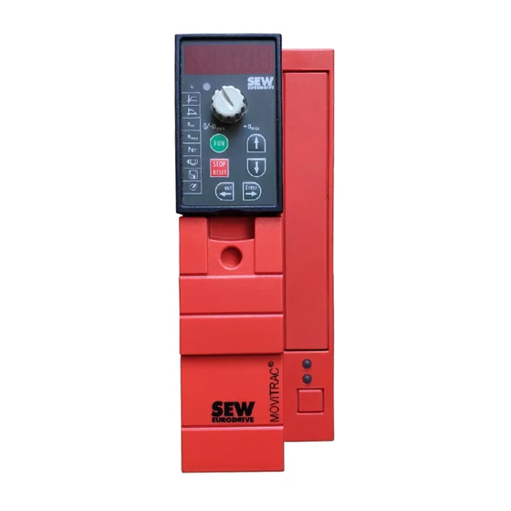
Assembly / Installation Instructions Installation of MOVI-PLC® basic DHP11B in MC 07B / compact control ® Installation of MOVI-PLC basic DHP11B in MC 07B / compact control ® MOVI-PLC basic DHP11B.. controller is installed as stipulated in section 3.4. The ®... - Page 29 Assembly / Installation Instructions Installation of MOVI-PLC® basic DHP11B in MC 07B / compact control ® MOVITRAC DHP11B FSC11B H L ⊥ 1 2 3 4 5 6 1 2 3 4 5 6 7 24V IO 59090AXX ® Fig. 8: Installation in MOVITRAC ®...
-
Page 30: Operating Displays Option Slot Movitrac
Assembly / Installation Instructions Installation of MOVI-PLC® basic DHP11B in MC 07B / compact control Compact control DHP11B SEW Drive 1 2 3 4 5 6 7 SC11 System Bus +, CAN high SC12 System Bus -, CAN low + 24 V GND, CAN GND 59088AEN ®... -
Page 31: Engineering Interfaces Of The Movi-Plc
Assembly / Installation Instructions Engineering interfaces of the MOVI-PLC® basic DHP11B.. controller ® Engineering interfaces of the MOVI-PLC basic DHP11B.. controller ® Use one of the following interfaces for engineering access to the MOVI-PLC basic DHP11B.. controller: • RS485 (connector X34, X24, X35) •... -
Page 32: 3.10 Shielding And Routing Bus Cables
Assembly / Installation Instructions Shielding and routing bus cables 3.10 Shielding and routing bus cables Having the bus cables correctly shielded attenuates parasitic interference, which can occur in an industrial environment. The following measures ensure the best possible shielding: • Manually tighten the mounting screws on the connectors, modules, and equipotential bonding conductors. -
Page 33: Project Planning And Startup
Project Planning and Startup For project planning using the MOVITOOLS® MotionStudio PC software Project Planning and Startup This section provides information on project planning and startup ® • for the MOVI-PLC basic DHP11B.. controller ® • for inverters controlled using the MOVI-PLC basic DHP11B.. - Page 34 Project Planning and Startup For project planning using the MOVITOOLS® MotionStudio PC software Configuring the The SEW communication server SECOS is started automatically and appears in the engineering task bar. interface To open the SEW communication server SECOS, double-click the icon < >...
- Page 35 Project Planning and Startup For project planning using the MOVITOOLS® MotionStudio PC software Configure the parameters of the PC interfaces as follows: • Click the right mouse button on the required "PC Communication Interface" and select [Configure] in the [Options] menu. •...
- Page 36 Project Planning and Startup For project planning using the MOVITOOLS® MotionStudio PC software ® Unit-specific tool • Click on the icon < > (Scan) in MOVITOOLS MotionStudio. The software now selection displays all units connected to the engineering PC (Æ following figure) in a tree struc- ture [1].
-
Page 37: For Project Planning Using The Movitools
Project Planning and Startup Configuring and starting up drives Configuring and starting up drives How to configure and startup drives is described in the following library manuals: Drive Manual ® ® ® MOVIDRIVE B MOVIAXIS Libraries MPLCMotion_MDX and MPLCMotion_MX for MOVI-PLC ®... -
Page 38: Configuring A Profibus-Dp Master
Project Planning and Startup Configuring a PROFIBUS-DP master Configuring a PROFIBUS-DP master ® You require a GSD file for configuring a PROFIBUS-DP master for the MOVI-PLC basic DHP11B.. controller ® The current version of the GSD file for the MOVI-PLC basic DHP11B.. - Page 39 Project Planning and Startup Configuring a PROFIBUS-DP master The SEW drive is available under the following path in the hardware catalog: PROFIBUS-DP +--Additional PERIPHERAL UNITS +--Drives +---SEW +--DPV1 +---MOVI-PLC The installation of the new GSD file is now complete. ® Project planning Proceed as follows to configure the MOVI-PLC basic DHP11B..
- Page 40 Project Planning and Startup Configuring a PROFIBUS-DP master ® 2. The MOVI-PLC basic DHP11B.. controller is now preconfigured with the 3PD configuration. To change the PD configuration, you have to delete the 3 PD module in slot 3. Next, add another PD module (e.g. 10PD) from the "MOVI-PLC" folder at slot 3 using the drag &...
- Page 41 Project Planning and Startup Configuring a PROFIBUS-DP master ® 3. Optionally, you can configure a MOVILINK parameter channel in the cyclic process data (Æ following figure). To do so, delete the "Empty" module from slot 2 and replace it by the module "Param (4words)" using drag & drop. 58370AXX ®...
- Page 42 Project Planning and Startup Configuring a PROFIBUS-DP master 4. Enter the I/O or peripheral addresses for the configured data widths in the "I Address" [1] and "Q Address" [2] columns. 58375AXX ® DP configuration To enable MOVI-PLC basic DHP11B.. controller to support the type and number of the input and output data used for transmission, the DP master must transmit the corre- ®...
- Page 43 Project Planning and Startup Configuring a PROFIBUS-DP master The following tables contain additional information on possible DP configurations. • The "Parameter data / Process data configuration" column displays the name of the configuration. These names also appear in a selection list in the configuration soft- ware for the DP master.
- Page 44 Project Planning and Startup Configuring a PROFIBUS-DP master Process Data Meaning / Notes DP configuration Configuration 16 PD Process data exchange via 0xC0, 0xCF, 0xCF 16 process data words 32 PD Process data exchange via 0xC0, 0xDF, 0xDF 32 process data words Configuration Slot 1: Empty example...
- Page 45 Project Planning and Startup Configuring a PROFIBUS-DP master The following figure shows the configuration data structure defined in IEC 61158. This ® configuration data is transmitted to the MOVI-PLC basic DHP11B.. controller during the initial start of the DP master. 7 / MSB 0 / LSB Data length...
-
Page 46: Procedure For Replacing The Unit
Project Planning and Startup Procedure for replacing the unit Procedure for replacing the unit ® When exchanging a MOVI-PLC basic DHP11B.. controller, a compact control or a controlled drive, proceed as described in sections 4.2 and 4.3. ® The "Version Management Tool" (MOVITOOLS MotionStudio Æ... -
Page 47: Profibus-Dp Operating Characteristics
PROFIBUS-DP Operating Characteristics Process data exchange with the MOVI-PLC® basic DHP11B.. controller PROFIBUS-DP Operating Characteristics ® This section describes the basic characteristics of the MOVI-PLC basic DHP11B.. controller connected to the PROFIBUS-DP system. ® Process data exchange with the MOVI-PLC basic DHP11B.. - Page 48 PROFIBUS-DP Operating Characteristics Process data exchange with the MOVI-PLC® basic DHP11B.. controller ® STEP7 example In this example, project planning for the MOVI-PLC basic DHP11B.. controller has the program process data configuration 10 PD on input addresses PIW512... and output addresses POW512...
-
Page 49: Profibus-Dp Timeout
PROFIBUS-DP Operating Characteristics PROFIBUS-DP timeout ® The following figure shows the corresponding project planning for the MOVI-PLC basic DHP11B.. controller in the hardware configuration of STEP7 (Æ Section "DP configura- tion", page 42). 58376AXX PROFIBUS-DP timeout ® The response monitoring time on the MOVI-PLC basic DHP11B.. -
Page 50: Parameter Setting Via Profibus-Dp
PROFIBUS-DP Operating Characteristics Parameter setting via PROFIBUS-DP Parameter setting via PROFIBUS-DP ® In the PROFIBUS-DP system, the parameters are accessed via the 8 byte MOVILINK parameter channel. This parameter channel offers extra parameter services in addition to the conventional read and write services. ®... - Page 51 PROFIBUS-DP Operating Characteristics Parameter setting via PROFIBUS-DP Management of The entire procedure for setting parameters is coordinated using management byte 0. the 8 byte This byte provides important service parameters, such as the service identifier, data ® MOVILINK length, version and status of the service performed. parameter channel ®...
- Page 52 PROFIBUS-DP Operating Characteristics Parameter setting via PROFIBUS-DP Data range As shown in the following table, the data is contained in byte 4 through byte 7 of the parameter channel. This means up to 4 bytes of data can be transmitted per service. The data is always entered with right-justification;...
- Page 53 PROFIBUS-DP Operating Characteristics Parameter setting via PROFIBUS-DP ® The MOVI-PLC basic DHP11B.. controller now processes the read service and sends the service confirmation back when the handshake bit changes. 7 / MSB 0 / LSB Service identifier 0001 = Read parameter Data length Not relevant for read service Handshake bit...
- Page 54 PROFIBUS-DP Operating Characteristics Parameter setting via PROFIBUS-DP The following table shows how a write service is coded in the management byte 0. The ® data length is 4 bytes for all parameters of the MOVI-PLC basic DHP11B.. controller. ® This service is now transferred to the MOVI-PLC basic DHP11B..
-
Page 55: Return Codes For Parameter Setting
PROFIBUS-DP Operating Characteristics Return codes for parameter setting Parameter data When parameters are set via the fieldbus interface, the same parameter coding is used format as with the serial RS485 interface or the system bus. Return codes for parameter setting ®... -
Page 56: Special Cases
PROFIBUS-DP Operating Characteristics Special cases ® Additional code The additional code contains SEW-specific return codes for errors in the MOVI-PLC basic DHP11B.. controller configuration. They are returned to the master under error class 8 = other error. The following table shows all possible codings for the additional code. - Page 57 PROFIBUS-DP Operating Characteristics Special cases Incorrect service Incorrect code was specified in the management byte or reserved byte during parameter code in the setting via the parameter channel. The following table shows the return code for this parameter channel special case. Code (dec) Meaning Error class:...
-
Page 58: Profibus-Dp-V1 Functions
PROFIBUS-DP-V1 Functions Introduction to PROFIBUS-DP-V1 PROFIBUS-DP-V1 Functions Introduction to PROFIBUS-DP-V1 ® This section describes the functions and terms used for operating the MOVI-PLC basic DHP11B.. controller on PROFIBUS-DP-V1. Refer to the PROFIBUS user organization or visit www.profibus.com for detailed technical information on PROFIBUS-DP-V1. The PROFIBUS-DP-V1 specification introduced new acyclical read / write services as part of the PROFIBUS-DP expansions. - Page 59 PROFIBUS-DP-V1 Functions Introduction to PROFIBUS-DP-V1 The PROFIBUS-DP-V1 network differentiates between various master classes. Class 1 master The C1 master essentially performs the cyclical data exchange with the slaves. A typical (C1 master) C1 master is a control system, such as a PLC, that exchanges cyclical process data with the slave.
-
Page 60: Features Of The Sew-Dp-V1 Interfaces
PROFIBUS-DP-V1 Functions Features of the SEW-DP-V1 interfaces Features of the SEW-DP-V1 interfaces The SEW fieldbus interfaces to PROFIBUS-DP-V1 have the same communication ® features as the DP-V1 interface. The MOVI-PLC basic DHP11B.. controller is usually controlled via a C1 master with cyclical process data in accordance with the DP-V1 stan- ®... -
Page 61: Structure Of The Dp-V1 Parameter Channel
PROFIBUS-DP-V1 Functions Structure of the DP-V1 parameter channel Structure of the DP-V1 parameter channel ® Generally, parameter settings for the MOVI-PLC basic DHP11B.. controller based on the PROFIdrive DP-V1 parameter channel of profile version 3.0 are made via data set index 47. - Page 62 PROFIBUS-DP-V1 Functions Structure of the DP-V1 parameter channel The following PROFIdrive services are supported: • Reading (request parameter) individual parameters of type double word • Writing (change parameter) individual parameters of type double word Field Data Type Values Request Unsigned8 0x00 reserved reference...
- Page 63 PROFIBUS-DP-V1 Functions Structure of the DP-V1 parameter channel Procedure for Parameter access is provided by the combination of the DP-V1 services write and read. setting The master transfers the parameter setting request to the slave by sending Write.req., parameters via followed by slave-internal processing.
- Page 64 PROFIBUS-DP-V1 Functions Structure of the DP-V1 parameter channel DP-V1 master If the bus cycles are very short, the request for the parameter setting response arrives ® processing before the MOVI-PLC basic DHP11B.. controller has concluded parameter access in ® sequence the device.
- Page 65 PROFIBUS-DP-V1 Functions Structure of the DP-V1 parameter channel Example for The following tables show an example of the structure of the Write.request and Read.res ® reading a user data for reading an individual parameter via the MOVILINK parameter channel. parameter via ®...
- Page 66 PROFIBUS-DP-V1 Functions Structure of the DP-V1 parameter channel ® Positive MOVILINK parameter response The two following tables show the Read.req user data with the positive response data of the parameter setting request. For example, the parameter value for index 8300 (firm- ware version) is returned.
- Page 67 PROFIBUS-DP-V1 Functions Structure of the DP-V1 parameter channel Query parameter response The following table shows the code of the Write.req user data including the DP-V1 header. Field Value Description Function_Num Read.req Slot_Number Slot_Number not used Index Index of data set Length Maximum length of response buffer in DP master Positive response to "Write Parameter volatile"...
- Page 68 PROFIBUS-DP-V1 Functions Structure of the DP-V1 parameter channel ® MOVILINK The following table shows the return codes that are returned by the SEW DP-V1 inter- return codes of face in case of an error in the DP-V1 parameter access. parameter setting ®...
- Page 69 PROFIBUS-DP-V1 Functions Structure of the DP-V1 parameter channel ® PROFIdrive The PROFIdrive parameter channel of the MOVI-PLC basic DHP11B.. controller is parameter directly mapped in the structure of data set 47. Parameter access with PROFIdrive requests services usually takes place according to the structure described below. The typical tele- gram sequence for data set 47 is used.
- Page 70 PROFIBUS-DP-V1 Functions Structure of the DP-V1 parameter channel Query parameter response The following table shows the code of the Read.req user data including the DP-V1 header. Service Read.request Slot_Number Random, (is not evaluated) Index Index of the data set; constant index 47 Length Maximum length of response buffer in the DP-V1 master Positive PROFIdrive parameter response...
- Page 71 PROFIBUS-DP-V1 Functions Structure of the DP-V1 parameter channel Example for writing The following tables show an example of the structure of the write and read services for a parameter via the remanent writing of the value 12345 to the variable H0 (parameter index 11000) ®...
- Page 72 PROFIBUS-DP-V1 Functions Structure of the DP-V1 parameter channel Positive response Write Parameter Service Read.response Slot_Number Random, (is not evaluated) Index Index of the data set; constant index 47 Length 4 byte user data in response buffer Byte Field Value Description Response reference 0x01 Reflected reference number from the parameter setting...
- Page 73 PROFIBUS-DP-V1 Functions Structure of the DP-V1 parameter channel PROFIdrive return The following table shows the coding of the error number in the PROFIdrive DP-V1 codes for DP-V1 parameter response according to PROFIdrive profile V3.1. This table applies if you use the PROFIdrive services Request Parameter or Change Parameter.
-
Page 74: Project Planning For A C1 Master
PROFIBUS-DP-V1 Functions Project planning for a C1 master Error no. Meaning Used at Supplem. Info. 0x18 Number of values is not Write request: Number of parameter data consistent values that do not match the number of elements in the parameter address 0x19 Axis nonexistent Access to an axis which does not exist... - Page 75 PROFIBUS-DP-V1 Functions Appendix Error codes of The following table shows possible error codes of DP-V1 services that may occur in the the DP-V1 event of an error in the communication on DP-V1 telegram level. This table is relevant services if you want to write your own parameter assignment block based on the DP-V1 services because the error codes are reported directly back on the telegram level.
-
Page 76: Error Diagnostics
Error Diagnostics Diagnostic procedure for system buses CAN 1 / CAN 2 Error Diagnostics Diagnostic procedure for system buses CAN 1 / CAN 2 Diagnostic problem: Communication via system bus CAN 1 or CAN 2 does not work. Initial status: •... -
Page 77: Diagnostic Procedure For Profibus-Dp
Error Diagnostics Diagnostic procedure for PROFIBUS-DP Diagnostic procedure for PROFIBUS-DP ® Diagnostic problem: The MOVI-PLC basic DHP11B.. controller does not work on PROFIBUS. Initial status: ® • The MOVI-PLC basic DHP11B.. controller is connected physically to PROFIBUS. ® • The MOVI-PLC basic DHP11B.. -
Page 78: Technical Data And Dimension Drawings
Technical Data and Dimension Drawings General technical data Technical Data and Dimension Drawings General technical data The general technical data listed in the following table apply to: ® • the MOVI-PLC basic DHP11B.. controller installed in the inverter or OST11B option ®... -
Page 79: Movi-Plc® Basic Dhp11B.. Controller
Technical Data and Dimension Drawings MOVI-PLC® basic DHP11B.. controller ® MOVI-PLC basic DHP11B.. controller ® MOVI-PLC basic DHP11B.. controller ® Unit design and part • MOVI-PLC basic DHP11B-T0: 1 820 472 4 ® number • MOVI-PLC basic DHP11B-T1: 1 820 822 3 ®... -
Page 80: Ost11B Option
Technical Data and Dimension Drawings OST11B option ® MOVI-PLC basic DHP11B.. controller System bus CAN 2 • System bus CAN 1 and CAN 2 to CAN specification 2.0, parts A and B, transmission technology to X32:1 ... X32:3 ISO 11898, max. 64 stations, •... -
Page 81: Movi-Plc® Basic Compact Control
Technical Data and Dimension Drawings MOVI-PLC® basic compact control ® MOVI-PLC basic compact control ® MOVI-PLC basic compact control ® Unit types • MOVI-PLC basic DHP11B-T0 / UOH11B ® • MOVI-PLC basic DHP11B-T1 / UOH11B ® • MOVI-PLC basic DHP11B-T2 / UOH11B ®... -
Page 82: Dimension Drawings Of Movi-Plc® Basic Dhp11B.. Compact Control
Technical Data and Dimension Drawings Dimension drawings of MOVI-PLC® basic DHP11B.. compact control / ® Dimension drawings of MOVI-PLC basic DHP11B.. compact control / UOH..B 8.5.1 Dimensions drawing DHP11B.. / UOH11B 22.5 58609AXX ® Manual – MOVI-PLC basic DHP11B.. controller... -
Page 83: Dimensions Drawing Dhp11B
Technical Data and Dimension Drawings Dimension drawings of MOVI-PLC® basic DHP11B.. compact control / 8.5.2 Dimensions drawing DHP11B../ OST11B / UOH21B OST 11B CTRL 22.5 58606AXX ® Manual – MOVI-PLC basic DHP11B.. controller... -
Page 84: Index Of Changes
Index of Changes Changes to the previous version Index of Changes Changes to the previous version The following section lists the changes made to the individual sections from edition 09/2005, publication number 11350717 (EN). New additions include: ® ® • The installation of the MOVI-PLC basic DHP11B.. -
Page 85: Index
Index Index 0...9 24V / I/O OK LED ..........21 Fault Profibus LED ..........22 Functional description of the terminals, DIP ® switches and LED of the MOVI-PLC basic Additional documentation ........6 DHP11B.. controller ........... 15 Automation topologies ..........8 GSD file Basic procedure for installing an option card in Installation in STEP7 ........ - Page 86 Index ® ® MOVI-PLC basic DHP11B.. in MOVILINK parameter channel MC07B / compact control ....28 Index addressing ......... 51 ® MOVI-PLC basic DHP11B.. in Management ..........51 ® MOVIDRIVE MDX61B .... 12 ® MOVILINK parameter channel ® MOVI-PLC basic DHP11B.. in the data range ........
- Page 87 Index Read parameter (Read) .......52 RS485 interface COM1 ........10 ® Structure of the MOVILINK parameter Run Profibus LED ..........22 channel ..........50 Write parameter (WRITE) ......53 Sample STEP7 program ........48 PROFIBUS-DP-V1 Shielding and routing bus cables ....... 32 Alarm handling ..........59 Structure of the DP-V1 parameter channel Appendix ............74...
- Page 88 16, rue des Frères Zaghnoun Fax +213 21 8222-84 Bellevue El-Harrach 16200 Alger Argentina Assembly Buenos Aires SEW EURODRIVE ARGENTINA S.A. Tel. +54 3327 4572-84 Sales Centro Industrial Garin, Lote 35 Fax +54 3327 4572-21 Service Ruta Panamericana Km 37,5 sewar@sew-eurodrive.com.ar...
- Page 89 Address List Australia Assembly Melbourne SEW-EURODRIVE PTY. LTD. Tel. +61 3 9933-1000 Sales 27 Beverage Drive Fax +61 3 9933-1003 Service Tullamarine, Victoria 3043 http://www.sew-eurodrive.com.au enquires@sew-eurodrive.com.au Sydney SEW-EURODRIVE PTY. LTD. Tel. +61 2 9725-9900 9, Sleigh Place, Wetherill Park Fax +61 2 9725-9905 New South Wales, 2164 enquires@sew-eurodrive.com.au Austria...
- Page 90 Address List China Assembly Suzhou SEW-EURODRIVE (Suzhou) Co., Ltd. Tel. +86 512 62581781 Sales 333, Suhong Middle Road Fax +86 512 62581783 Service Suzhou Industrial Park suzhou@sew.com.cn Jiangsu Province, 215021 P. R. China Additional addresses for service in China provided on request! Colombia Assembly Bogotá...
- Page 91 Address List Hungary Sales Budapest SEW-EURODRIVE Kft. Tel. +36 1 437 06-58 Service H-1037 Budapest Fax +36 1 437 06-50 Kunigunda u. 18 office@sew-eurodrive.hu India Assembly Baroda SEW-EURODRIVE India Pvt. Ltd. Tel. +91 265 2831086 Sales Plot No. 4, Gidc Fax +91 265 2831087 Service Por Ramangamdi ·...
- Page 92 Address List Luxembourg Assembly Brüssel CARON-VECTOR S.A. Tel. +32 10 231-311 Sales Avenue Eiffel 5 Fax +32 10 231-336 Service B-1300 Wavre http://www.caron-vector.be info@caron-vector.be Malaysia Assembly Johore SEW-EURODRIVE SDN BHD Tel. +60 7 3549409 Sales No. 95, Jalan Seroja 39, Taman Johor Jaya Fax +60 7 3541404 Service 81000 Johor Bahru, Johor...
- Page 93 Address List Romania Sales Bucuresti Sialco Trading SRL Tel. +40 21 230-1328 Service str. Madrid nr.4 Fax +40 21 230-7170 011785 Bucuresti sialco@sialco.ro Russia Assembly St. Petersburg ZAO SEW-EURODRIVE Tel. +7 812 3332522 +7 812 5357142 Sales P.O. Box 36 Fax +7 812 3332523 Service 195220 St.
- Page 94 Address List Sweden Assembly Jönköping SEW-EURODRIVE AB Tel. +46 36 3442-00 Sales Gnejsvägen 6-8 Fax +46 36 3442-80 Service S-55303 Jönköping http://www.sew-eurodrive.se Box 3100 S-55003 Jönköping info@sew-eurodrive.se Switzerland Assembly Basel Alfred lmhof A.G. Tel. +41 61 417 1717 Sales Jurastrasse 10 Fax +41 61 417 1700 Service CH-4142 Münchenstein bei Basel...
- Page 95 SEW-EURODRIVE – Driving the world...
- Page 96 Gearmotors \ Industrial Gear Units \ Drive Electronics \ Drive Automation \ Services How we’re driving the world With people who With comprehensive With uncompromising think fast and With a worldwide With drives and controls knowledge in virtually quality that reduces the develop the service network that is that automatically...
Need help?
Do you have a question about the MOVI-PLC basic DHP11B-T0 and is the answer not in the manual?
Questions and answers