Table of Contents
Advertisement
Quick Links
1. Cautions
Please note the following cautions. Mis-operation may lead to personal injury or equipment failure:
1) Do not energize the system before installation is complete; never carry out installation activities when the system is energized. Check the correctness of cable connection
before you energize the system.
2) All peripheral devices must be grounded.
3) The conduits of wires under relay must be matched with metaled conduits, other wires can use PVC conduits.
4) It is strongly recommended that the length of exposed part of any connection cable should not be longer than 4 mm. Professional clamping tools may be used to avoid
unintentional contact of exposed wires to avoid short-circuit or communication failure.
5) It is recommended that the control panel be installed at height of 2m above ground, card readers and buttons be installed at height of 1.4m-1.5m above ground.
6) It is not recommended that the electrical lock and control panel use the same power supply. It is recommended that the control panel use the provided access control
power supply or PoE, and the electrical lock use an external power supply separately.
Description of normal working state:
Connect the system to the power supply. If the system works properly, the POWER indicator (red) is lit constantly and the RUN indicator (green) flashes. If the system is
communicating, the COMM indicator (yellow) flashes.
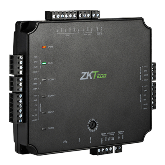
2. Components
Heat Dissipation
Hole
Box Lock Hole
Antenna
Power
Connector
Interface
Panel Box Appearance
3. Installation
If the provided chassis is used, the control panel has been installed inside the chassis by default. Fix the chassis on the wall, remove the hole plug or get through the thread
hole, connect the access control cable, and install other components.
Remarks: The control panel has a guide rail on the back. If you need to install the control panel separately without the chassis, you can use the guide rail to fix the control
panel. The following figures show how to fix the control panel using the guide rail.
Thread Hole
1) Remove the hole plug or get
through the thread hole
C5S110 Installation and Connection Guide
State Indicator
Thread
Hole
2) Fix the guide rail on the wall
Control Panel
Power Adapter
Panel Box Inside
Version: V1.1
Temper Switch
Get the Panel off the track
(Remove the set screws)
Control Panel
Guide Rail
3) Install other components
Advertisement
Table of Contents

Related Manuals for ZKTeco C5S110


Summary of Contents for ZKTeco C5S110
- Page 1 C5S110 Installation and Connection Guide Version: V1.1 1. Cautions Please note the following cautions. Mis-operation may lead to personal injury or equipment failure: 1) Do not energize the system before installation is complete; never carry out installation activities when the system is energized. Check the correctness of cable connection before you energize the system.
- Page 2 4. LED Indicators and Wire Illustration 1) Meaning of LED indicators: POWER indicator (red): light always indicates control panel is power on. RUN indicator (green): flashing indicates the system works normally. COMM1 indicator (yellow): flashing indicates the system is communicating with upper-level devices (for example, the PC). COMM2 (yellow): flashing indicates the system is communicating with lower-level devices (for example, readers).
- Page 3 5. DIP Switch Settings The 0–F bits of the rotary DIP switch indicate device numbers 1–16 during RS485 communication. (Switch 0 indicates device number 16, switch 1 indicates device number 1, and so on. Switch F indicates device number 15). You can rotate the 0–F bits of the rotary DIP switch to corresponding positions to set device numbers, and then restart the control panel to make the setting take effect.
- Page 4 For example, use the KR502M-RS card reader, the standby current is less than 80mA, the max current is less than 90mA, When the device is start, Instantaneous current can reach 180 mA. As RS485 reader, consider the starting current is bigger, through the EXT RS485 interface can only connect four readers for power supply.
- Page 5 8.3 Wireless Communication 1) Create a valid connection string using TCP/IP, and make sure that there is available WiFi network. 2) Input the IP address of the controller (factory default is 192.168.1.201) in the address bar; enter the user name and password (both are admin), and click [Sign In] to access the ZKPanelWeb.
- Page 6 figure 1 figure 2 Note: The PC (server) must be on the same network segment as the router (wireless network). 6) Switch network connection in the software. For ZKAccess3.5 software: Select the added C5S control panel on the Device page and click [More…] > [Set up WiFi], as figure 3, set the WIFI parameters of the control panel based on the router parameters.
Need help?
Do you have a question about the C5S110 and is the answer not in the manual?
Questions and answers