
Related Manuals for SMC Networks ZFC Series


Summary of Contents for SMC Networks ZFC Series
- Page 1 No.FGX-OM-Q013-A PRODUCT NAME In-line Air Filter MODEL / Series / Product Number Series ZFC ZFC1∗-∗ ZFC3∗-∗ ZFC5∗-∗ ZFC7∗-∗...
-
Page 2: Table Of Contents
Contents Safety Instructions Series ZFC specific product precautions 1. Product components and functions 2. Specifications 3. Mounting P.11 4. Element Replacement P.12 - 1 -... -
Page 3: Safety Instructions
In-line Air Filter Safety Instructions These safety instructions are intended to prevent hazardous situations and/or equipment damage. These instructions indicate the level of potential hazard with the labels of “Caution,” “Warning” or “Danger.” They are all important notes for safety and must be followed in addition to International Standards (ISO/IEC) , and other safety regulations. - Page 4 In-line Air Filter Safety Instructions Caution 1.The product is provided for use in manufacturing industries. The product herein described is basically provided for peaceful use in manufacturing industries. If considering using the product in other industries, consult SMC beforehand and exchange specifications or a contract if necessary.
-
Page 5: Series Zfc Specific Product Precautions
Series Specific product precautions (1) Be sure to read before handling. Refer to “Handling Precautions for SMC Products” (M-E03-3) for Safety Instructions. Design Air Supply Warning Warning 1. Confirm the specifications. 1. Type of fluids Products represented in this catalog are designed Please consult with SMC when using the product in only for use in compressed air systems (including applications other than compressed air. - Page 6 Series Specific product precautions (2) Be sure to read before handling. Refer to “Handling Precautions for SMC Products” (M-E03-3) for Safety Instructions. Handling Precautions Maintenance Warning Warning Use of intermittent air blow may increase piping 5. The performance of an ejector will deteriorate due temperatures.
-
Page 7: Product Components And Functions
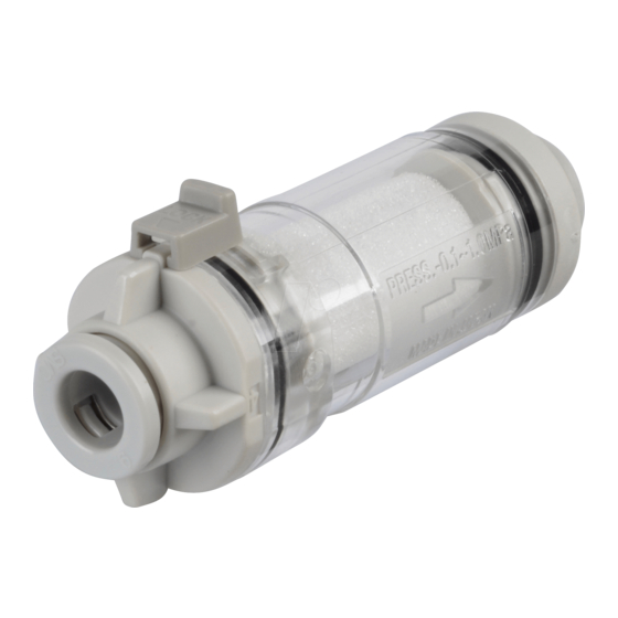
1. Product components and functions Product number label Table 1 Name and function of components Description Material Function Catches foreign matter. Element (Replace the element when it is clogged.) Vessel body (The clogging of the element can be checked Case visually). -
Page 8: Specifications
2. Specifications 2-1 How to Order Z F C □ □-□ Body size Option Filtration None Symbol Body size area With bracket Applicable tubing O.D. 5 L/min 140 mm Metric size 10 L/min 470 mm Applicable Symbol ZFC1 ZFC3 ZFC5 ZFC7 20 L/min 750 mm... - Page 9 2-2 Specifications Remarks Specifications This product cannot be used in an environment Fluid Air, Nitrogen exposed to chemicals. The maximum operating pressure varies depending on the temperature. Refer to the graph below for the relation between the operating temperature and maximum operating pressure.
- Page 10 2-3 Dimensions 1) ZFC1∗-∗ Applicable tubing O.D. ( φ2,φ3.2,φ1/8”) 2) ZFC3∗-∗ Applicable tubing O.D. (φ3.2,φ4,φ1/8”,φ5/32”) 3) ZFC5∗-∗ Applicable tubing O.D. ( φ4,φ6,φ5/32”,φ1/4”) - 9 -...
- Page 11 4) ZFC7∗-∗ Applicable tubing O.D. (φ6,φ8,φ1/4”,φ5/16”) Applicable tubing O.D. ( φ10,φ12,φ3/8”) - 10 -...
-
Page 12: Mounting
3. Mounting 1) Tube connection - Check the IN side and OUT side before connecting the tube. IN/OUT direction can be identified by the arrow (showing the flow direction) displayed on the transparent case. Flow direction Note) When replacing the element, ensure that there is enough space for removing the cover (IN side). Note) Refer to "One-touch Fittings Precautions"... -
Page 13: Element Replacement
4. Element Replacement Replace the element at least once a year or when the following conditions apply. 1) When pressure drop reaches 0.1MPa in a positive pressure or 20kPa in a vacuum pressure. 2) When the set values (flow rate, time required to reach the specified vacuum) change. Replacement Element Part no. - Page 14 Revision history Rev.A: The ZFC1series and ZFC3 series added. 4-14-1, Sotokanda, Chiyoda-ku, Tokyo 101-0021 JAPAN Tel: + 81 3 5207 8249 Fax: +81 3 5298 5362 http://www.smcworld.com Note: Specifications are subject to change without prior notice and any obligation on the part of the manufacturer. ©...
Need help?
Do you have a question about the ZFC Series and is the answer not in the manual?
Questions and answers