Autonics GP Series User Manual
Hide thumbs
Also See for GP Series:
- User manual for communication (50 pages) ,
- Solution manual (40 pages) ,
- User manual (36 pages)

Related Manuals for Autonics GP Series


Summary of Contents for Autonics GP Series
- Page 1 GP Series USER MANUAL Thank you very much for selecting Autonics products. For your safety, please read and keep this instruction carefully before using.
- Page 2 ▣ Precaution for safety ※ Please keep the following for preventing from the accident or danger with safety using. ※ ‘Precaution for safety’ is consisted of ‘Warning’ and ‘Caution’, please refer to the following. Warning Serious injury or death possibly caused if this instruction is not followed. Caution Slight wound or product damage could possibly caused if this instruction is not followed.
- Page 3 Warning 1. Do not use on devices that require high safety and stability (ex: nuclear energy systems, power supply, medical devices, aircraft control devices, combustion devices, automobiles, riding, moving parts, etc.) It may cause a fire, human injury or property loss. 2.
- Page 4 Caution 1. Please read all notes related to installation and wiring in the manual. If this is not observed, electrical shock or malfunction may occur. 2. Make sure the ground wire of Graphic Panel is wired separately from the ground wires of other devices.
- Page 5 15. To change the battery, contact the store or an authorized technician. 16. The manufacturer is not liable for damages that occur due to causes for which the manufacturer is not responsible, damages that occur due to an extraordinary situation, secondary damages, compensation for accidents, damages occurring on other products, compensation for other processes, and damage and loss of opportunity to the user due a malfunction of the product, regardless of the predictability of the accident.
-
Page 6: Table Of Contents
CONTENTS OUTLINE ............................ 15 1.1 THE DEFINITION OF GP ......................15 1.2 THE FEATURE OF GP2480 ......................16 1.3 ORDERING INFORMATION ......................17 1.4 THE RATING ..........................18 1.5 SPECIFICATIONS ........................20 1.6 SERIAL CONNECTION SPECIFICATIONS ................22 1.6.1 Serial port ..........................22 1.6.2 Connection of PLC ........................ - Page 7 3.6.1 Data transmission ........................55 3.6.2 Time switch ..........................56 3.6.3 Print out ............................. 57 4. USER SCREEN ..........................58 4.1 SCREEN SPECIFICATION ......................58 4.2 SCREEN DISPLAY OBJECTS ....................61 4.3 SCREEN SWITCHING ........................ 62 4.5 DISPLAY OF DEVICE CONNECTION STATUS ................65 5.
- Page 8 8.1.2 Window screen ......................... 98 8.2 CREATE NEW SCREEN ......................100 8.2.1 Operation procedure ....................... 100 8.2.2 Adjustment after design ......................101 8.2.3 Precaution of designing key window ..................101 8.2.4 Screen property ........................103 8.3 LOAD SCREEN ......................... 104 8.3.1 Operation procedure .......................
- Page 9 10.3.3 Adjust size of object ......................126 10.4 PART/PANEL KIT LIBRARY ....................127 10.4.1 Panel kit window ........................127 10.4.2 View/draw contents of library ....................128 10.4.3 Create/delete panel kit library ....................128 10.4.4 Register/delete/copy kit in panel kit library ................129 10.4.5 Save/import panel kit library ....................
- Page 10 13.3.1 PLC connection ........................161 13.3.2 Configuration of connection PLC with GP/PLC type window ..........162 13.3.3 Data link of CH1 ........................163 13.3.4 Data link of CH2 ........................165 13.3.5 Switch device for changing PLC type ................... 168 14.FIGURE ............................170 14.1 LINE ............................
- Page 11 18. ASCII INPUT ..........................194 18.1 BASIC CONFIGURATION ....................... 194 18.2 BASIC OPERATION ........................ 194 18.3 DETAIL CONFIGURATION AND OPERATION IN MAIN DEVICE .......... 196 18.3.1 Basic tap ..........................196 18.3.2 Form tap ..........................197 18.3.3 Trigger tap ..........................198 18.3.4 Option tap ..........................
- Page 12 23.1.2 Word operation ........................227 23.2 EDIT PROCEDURE IN EDITOR ....................227 23.3 Detail configuration and operation ................... 228 23.3.1 Basic tap ..........................228 23.3.2 Bit tap ............................ 230 23.3.3 Word ............................231 24. LAMP DISPLAY ......................... 232 24.1 EDIT PROCEDURE IN EDITOR ....................232 24.2 BASIC OPERATION ........................
- Page 13 29. PANEL METER .......................... 258 29.1 BASIC FUNCTION OF PANEL METER .................. 258 29.2 BASIC CONFIGURATION IN EDITOR ..................258 29.3 DETAIL CONFIGURATION AND OPERATION OF MAIN DEVICE ......... 259 29.3.1 Basic tap ..........................259 29.3.2 Form tap ..........................260 29.3.3 Graph tap ..........................
- Page 14 34.1.1 Operation procedure ......................285 34.1.2 Operation type ........................286 34.2 DETAIL CONFIGURATION AND OPERATION IN EDITOR ............ 287 34.2.1 Project tap ..........................288 34.2.2 Screen tap ..........................288 34.2.3 Trigger tap ..........................289 34.2.4 Operation tap ........................290 35. RECIPE ............................292 35.1 CONFIGURATION IN EDITOR ....................
-
Page 15: Outline
1. OUTLINE 1.1 THE DEFINITION OF GP GP(Graphic Panel) is a graphic interface device to monitor parameters of controllers as PLC. It is one of HMI(Human-Machine Interface) or MMI(Man-Machine Interface). It is used to find out current value and status of process between controller and user, it also available to monitor control parameter on LCD screen, switch touch screen or set a variable. -
Page 16: The Feature Of Gp2480
1.2 THE FEATURE OF GP2480 Product upgrade in Web site GP OS, GP Editor, protocol, language, font and various manuals can be downloaded in www.autonics.com. Heterogeneous controllers communication Different model of controllers can be connected to serial ports separately. -
Page 17: Ordering Information
1.3 ORDERING INFORMATION 2480 SB D 0 ① ② ③ ④ ⑤ ① Series Graphic panel ② LCD resolution 2480 240X80 dots ③ LCD type STN BLUE ④ Power 24VDC ⑤ Serial port RS232C, RS422 2 ports of RS232C Item Graphic panel ①... -
Page 18: The Rating
1.4 THE RATING GP-2480 Model 24VDC ±10% Power supply 3.6W max Power consumption The square wave noise (Pulse width 1㎲) by the noise simulator Noise strength with ±1000V R/S phase and repetition frequency 60Hz 500VAC(50/60Hz) for a minute Dielectric strength Insulation resistance Min. - Page 19 24VDC ±10% Power supply 3.6W max Power consumption The square wave noise (Pulse width 1㎲) by the noise simulator Noise strength with ±1000V R/S phase and repetition frequency 60Hz Dielectric strength 500VAC(50/60Hz) for a minute Insulation resistance Min. 100MΩ (at 500VDC) Ground grounding (Max.
-
Page 20: Specifications
1.5 SPECIFICATIONS Model xx-xxxx-xxD0 xx-xxxx-xxD1 LCD type STN Blue Negative Resolution 240 X 80 dots Display area 112.8mm X 37.6mm Color Single color (Blue, White) LCD visible angle 30° of Up/Down/Left/Right direction Backlight White LED Battery life cycle 3 years at 25℃ Brightness Adjust as software Serial communication... - Page 21 Device Monitoring Monitor connected PLC device and change the status. Monitoring (*)input/output Device Monitor the state of Input/output (supported in LP Series only) Monitoring Language selection Designate system language and character set. Configure connection device of serial port connected to CH1, CH2, Channel connection editor, printer, barcode reader and serial setup.
-
Page 22: Serial Connection Specifications
1.6 SERIAL CONNECTION SPECIFICATIONS 1.6.1 Serial port Port Pin(GP-2480) Pin(GP-S057) Pin(LP-S044) RS232C Non-used Non-used Non-used Non-used Non-used Non-used D-Sub 9Pin Non-used Non-used Non-used Male Non-used Non-used Non-used RS422 TXD+ TXD+ TXD+ RXD+ RXD+ RXD+ RTS- Non-used Non-used CTS+ Non-used Non-used TXD- TXD- TXD-... -
Page 23: Configuration Of Serial Port
◎Connection of CH1 and CH2 •Connect PLC to both RS232C/RS422 port. •GP observes CH1 mainly and accesses specified data register of CH2. •It is able to connect even if CH and CH2 are not same type and GP can relay data exchange between CH1 and CH2 according to configuration. -
Page 24: Dimensions And Description Of Parts
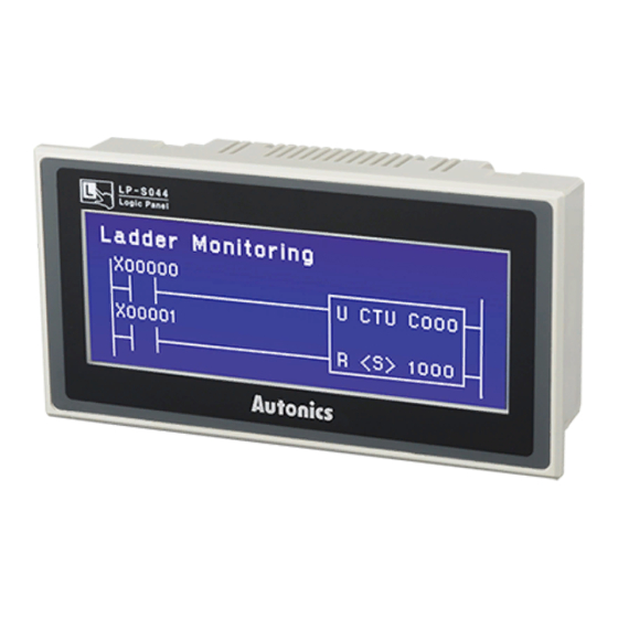
1.7 DIMENSIONS AND DESCRIPTION OF PARTS 1.7.1 Parts description •GP-2480 GP-2480 LCD screen AUTONICS Fixing brackets GRAPHIC PANEL Built-in battery case Power RS422 port RS232C port terminal or RS232C port block... - Page 25 •LP-S044 LCD Screen Fixing brackets Run/Stop Switch LED Power LED: ON(Green) Green On (RUN) Green On/Off (Pause) Orange On (Debug) Red On/Off (Error) Red Off (Stop) Power Input connector terminal block Output connector RS422 port RS232C port or RS232C port...
- Page 26 •GP-S057 Fixing brackets Fixing brackets Power LCD Screen terminal block...
-
Page 27: Dimensions
1.7.2 Dimensions Color : IVORY Unit : mm •GP-2480 •LP-S044... -
Page 28: The Fixing Bracket (20060407)
•GP-S057 1.7.3 The fixing bracket (20060407) Unit : mm •GP-2480, LP-S044... - Page 29 •GP-S057...
-
Page 30: Panel Cut-Out
1.7.4 Panel cut-out Unit : mm •GP-2480, LP-S044 *100 이상 : Min.100 * Over 100 : Min. 100 •GP-S057... -
Page 31: Installation Procedure
1.8 INSTALLATION PROCEDURE (1) Set a rubber waterproof ring in GP. (2) Set GP in panel. (3) Set brackets in 4 bracket slots and fix them. Mounting slot for bracket ※ Procedure of mounting bracket Approx. 0.3Nm... -
Page 32: The Wiring Of Power
1.9 THE WIRING OF POWER •Please use the power line as min.0.75mm , ground wire as min.1.25mm of dimension. •Please use crimp-on type ring terminal with min.3mm of inside diameter and max. 6mm of external diameter. •Please check power is on before connecting a power line. •Please check power polarity. -
Page 33: Start Up
2. START UP This chapter explains a whole procedure from putting main power into GP to switching as user screen. 2.1 START UP PROCEDURE provides Check the connection status of RS- various types 232C and RS-422 connector. connection. Please refer “Communication manual”. -
Page 34: Initial Screen Display
2.2 INITIAL SCREEN DISPLAY It displays model name, production year on the initial screen. The version information in lower-right indicates GP firmware version. The upgrade of regional language, fonts, protocol are executed in GP Editor. ※Notice • The initial screen display can be changed as releasing date of product. •... -
Page 35: System Display
3. SYSTEM DISPLAY 3.1 ORGANIZATION OF SYSTEM DISPLAY SCREEN Menu screen including monitoring, preference, data check and function configuration is displayed when touching system screen access key. When each item is selected, the sub menus is displayed for each item. The whole screen organization is as below. Organization of system menu Monitoring Preference... -
Page 36: Operation Of System Display Screen
3.2 OPERATION OF SYSTEM DISPLAY SCREEN It shows the menu It moves to title of current the prior item. screen. It moves from system configuration It moves to screen to user the upper screen. item as one space. When the appropriate menu is touched, it It moves to... -
Page 37: Monitoring Menu
3.3 MONITORING MENU 3.3.1 Device Monitoring It monitors the connected inner device or configures the value at specified device. The applicable device can be differed from connected model, it is available to monitor bit and word device of connected machinery, special function of device, inner bit device and inner word device area of GP. Please refer to communication manual for confirming monitor each device. -
Page 38: Monitoring I/O Device
3.3.2 monitoring I/O device The Menu for I/O device monitoring is only supported in LP Series Function and Operation Monitor the states of a Input contact points, X0 ~ X0 ① Monitor the states of a output contact points, Y0 ~ YF ②... -
Page 39: Data Check Mode
3.4 DATA CHECK MODE 3.4.1 Base display screen It shows the number of base screen and title list. The design status of the screen can be confirmed when touching a screen list. Screen check and operation When touching on the screen called, it When touching a screen number returns to basic screen list menu. -
Page 40: Comment List
3.4.3 Comment list It checks the downloaded comment of user. 3.4.4 Check used memory It displays used memory for design data and additional memory in 512 Kbyte of available user memory. 3.4.5 Check model and version It displays model name of GP and firmware version. -
Page 41: Preference Menu
5 PREFERENCE MENU It confirms the configuration status of GP operation and resets it. It can effect on the operation of GP as configuration status, it is designed to set password and cancel for protection of screen. It is also available to check the current status of configuration on the right part for each item. -
Page 42: Selection Of Language
3.5.1 Selection of language It displays the language using in system screen of GP, user screen and ASCII character fonts and it is available to set as the system menu language selecting one between using language and English. Language types – Korean, English and other languages are also available later on. Font types –... -
Page 43: Connection Of Plc
3.5.2 Connection of PLC It displays/configures the device connected to RS232C, RS422 port of GP and configure the station of GP and device. Connection port PLC protocol 1. CH1 configuration line 2. CH2 configuration line 4. CH1 station configuration touch key 3. - Page 44 - In case of download configuring to use CH1 only in editor. Item description Operation when it touched It rotates as Downloaded protocol → Editor → Printer → It shows the protocol of CH1. ① Barcode → Universal → Default protocol. In case of GP-2480-SBD0, it rotates as RS422 A PORT ↔...
- Page 45 - In case of download configuring to use CH2 only in editor. Item description Operation when it touched It rotates as Downloaded protocol → Editor → Printer → It shows the protocol of CH1. ① Barcode → Universal → Default protocol. In case of GP-2480-SBD0, it rotates as RS422 A PORT ↔...
- Page 46 - Detail configuration of CH1/CH2 Number Function and operation It configures operation mode. CH1,2 protocol : PLC configured and downloaded in GP and editor communicates to each port. Editor : It is an I/O mode and it is available to download user design data from GP Editor. Printer : It is an output mode and prints alarm list of GP.
-
Page 47: Current Time
3.5.3 Current time It sets and checks the current time. Number Function and operation There are 12 input buttons to set date and time. 0~9 : It inputs setting time. CLR : It cancels inputting of setting value and clears a cursor. ... -
Page 48: Delete User Data
3.5.4 Delete user data 3.5.4.1 Default GP Data It deletes user data of GP and the deleted data cannot be restored. In order to preserve alarm history, select [communication]-[upload] of main menu and check “Alarm history (ALHISTRY.TXT)” and “Alarm frequency (ALFREQUE.TXT)” to save as txt file. In case, GP is connected with serial printer, select [Preference]-[Print up]-[Alarm history] and it can be saved after printing it. - Page 49 3.5.4.2 Default LP Data This menu is only supported at LP Series only This menu deletes LP User Data Functions and Operations Deletes all of ladder programs and parameters and device data Display a Message which show the now state of deleting while deleting all item data ...
-
Page 50: Configuration/Access Key
3.5.5 Configuration/access key It is used to check the position of key for moving from user screens to system screens or re-configure. Number Function and operation It is set as configuration/access key position. It is not set as configuration/access key. ... -
Page 51: Buzzer
3.5.6 Buzzer It configures buzzer sound for touch key operation, touch of numeric, ASCII input, system configuration menu and notification for start/end of communication. Number Function and operation It operates buzzer when it touched. It notifies the alternated item is configured. ... -
Page 52: Backlight
It displays the time for switching from current configured initial screen to user screen. When touching time display position to reconfigure, a cursor is appeared and it is able to input time to configure. ※Reference • In the initial screen, it is available to check basic information of the product. (Releasing year, firmware version) 3.5.8 Backlight It configures time of putting out backlight of LCD. -
Page 53: Battery
The configuration and operation of backlight is valid when the status of backlight control device is set (ON) and it is not worked when it is reset (OFF). Please refer to the detail for system information. 3.5.9 Battery It is displayed as percentage for battery remaining. Number Function and operation ... -
Page 54: Screen Contrast
3.5.10 Screen contrast It configures the color contrast of screens. Number Function and operation It displays the current configuration status within 1/32 ~ 32/32. It displays the configured screen contrast ratio as graphic. ○ 3 It lowers contrast ratio when it touched. ④... -
Page 55: Function Configuration Mode
3.6 FUNCTION CONFIGURATION MODE 3.6.1 Data transmission It is displayed during a communication (Upload, download) with GP Editor of PC. Standby status Download Upload... -
Page 56: Time Switch
3.6.2 Time switch It executes ON/OFF the specified bit device of connected apparatus when it is on the designated day and time. It is configured in time action of GP Editor or time switch menu. It is only changed in GP Editor and it is not available on GP, the configuration of time switch operation time is only available. -
Page 57: Print Out
3.6.3 Print out It transmits alarm history list stored during GP operation to external printer. Number Function and operation It prints alarm history list when it touched. Configuration of printer port Configures the connection as printer in [Preference]-[Serial port]. CH1 does not use the out port of printer. -
Page 58: User Screen
4. USER SCREEN It is a base or window screen designed with GP Editor and this chapter describes the specification of base and window screens. 4.1 SCREEN SPECIFICATION □the size of a base screen The size base screen is a size included the size of a screen full area the size of a base screen as a model model the size of a base screen... - Page 59 □the size of a window screen The size of a window screen has a various size. You can determine a window size and it’s position in GP editor, and can assign the number of a window, which is unique from other window screen numbers like a base screen in GP editor the size of a window screen as a model model minimum size...
- Page 60 Model contents Base screen Window screen Start position of (0, 0) ~ (223, 59) screen (0,0) (left-upper point) GP-2480 end position of LP-S044 screen (239, 79) (15, 19)~(239, 79) (right-lower point) Start position of (0, 0) ~ (223, 59) screen (0,0) (left-upper point) GP-S057...
-
Page 61: Screen Display Objects
4.2 SCREEN DISPLAY OBJECTS □Available display objects for screens Base screen Window screen Line, Rectangle, Circle, Line, Rectangle, Circle, Character, Character, Bitmap, Bitmap, Numeric display, ASCII display, Numeric display, ASCII display, Clock display, Comment list, Parts Numeric input, ASCII input, display, Lamp display, Line graph, Available display Clock display, Comment list,... -
Page 62: Screen Switching
4.3 SCREEN SWITCHING □ Screen switching device The designed user screen in GP Editor has own number and it is downloaded to GP, it decides base screens to display switching device of base screen periodically. The switching device of screen is designated in editor. - Page 63 4.4 OVERLAP WINDOW FUNCTION GP monitors user-defined of 2 screen overlap devices and overlaps the screen satisfying current value of the device on a base screen. In order to use screen overlap function, configure device for overlap window in GP Editor. The overlap window is displayed in order of window 1, 2 on current screens as below.
- Page 64 □Example of overlap screen operation It describes assuming D0 is configured as screen access device, D1 as overlap window 1 device, D2 as overlap window device 2. All user-defined base screen numbers : 1,2,3,4,5,6,7,8 In case of values as D0=1, D1=3, D2=11, Base screen Overlap window 1 screen Screen number...
-
Page 65: Display Of Device Connection Status
4.5 DISPLAY OF DEVICE CONNECTION STATUS GP displays a message when the device configured in [PLC connection] menu is not connected or there is an error as below. The error message is appeared when touching a message window but it is popped an error message again if it is not recovered. -
Page 66: System Key Window
5. SYSTEM KEY WINDOW 5.1 KEYPAD TYPES Illustration of system keypad For hexadecimal input For decimal input For binary input For octal input For real number input For ASCII input... -
Page 67: Organization Of Keypad
5.2 ORGANIZATION OF KEYPAD Input display Buttons for window inputting value of displaying input configuration status form ENT: Execute write or input operation of writing value on a device. CLR: Delete all input value. BS: Delete the last letter. ▲: Move to the previous input field in accordance with configuration ▼: Move to the next input field in accordance with configuration ◀: Move to the previous page (Only for ASCII input key window) ▶: Move to the next page (Only for ASCII input key window) -
Page 68: The Outline Of Gp Editor
6. THE OUTLINE OF GP EDITOR 6.1 ORGANIZATION OF EDITOR PROGRAM WINDOW ① ② ③ ⑬ ④ ⑤ ⑥ ⑦ ⑪ ⑧ ⑫ ⑨ ⑩ Number Name Description Title bar Display number and title of working screen. ① Main menu Menu for all editing function ②... -
Page 69: Organization And Description Of Main Menu
6.2 ORGANIZATION AND DESCRIPTION OF MAIN MENU Menu Shortcut Description Project Create a new project. Ctrl+N Open Open saved project Ctrl+O Close Close project Save Save project Ctrl+S Save as Save project as other name Import project Import base screen, window screen, part, comment on current project. - Page 70 Select object-Tag Select tag Group Group selected objects Ungroup Disorganize group Bring to forward Move selected object to the forward Ctrl+F Send to backward Move selected object to the backward Ctrl+B Replace device Change device used for tag and it is available to select applicable range as all project, current screen, selected object, used device for common configuration.
- Page 71 accordance with ON/OFF of designated bit device. Panel meter Create panel meter tag, indicate percentage of max/min. value of designated word device with meter needle. Line/Trend/Bar Create line/trend/bar graph tag, display designated word device value with line/trend/bar graph type. Statistic graph Create statistic graph tag, display percentage of designated word device value as graph.
- Page 72 Download object. Common Title-Project Allow title and detail description of project. Title-Screen Allow title and detail description of screen. PLC connection Confirm and change of connection PLC. System information Define facts about device using for special purpose. Switching screen Designate device using switching screen. Security Able to designate password for security level, usage of security for system screen and communication security.
-
Page 73: Description Of Tools
6.3 DESCRIPTION OF TOOLS Icon Menu Description Project-New Create new project. Project-Open Open saved project. Project-Save Save project. Screen-New Create new screen. Screen-Load Load closed screen. Screen-Store Store screen. Edit-Undo Undo movement, delete, size adjustment. Edit-Cut Cut selected object. Edit-Copy Copy selected object. - Page 74 Draw-Line Able to draw line, create straight line connecting 2 points and designate color, style of line Draw-Rectangle Able to draw rectangle, color and style of outline and pattern filled inside of rectangle Draw-Circle Able to draw circle, designate outline color, pattern filled inside of rectangle and make an oval pulling a line Draw-Text Able to draw text and designate color and size of letter...
- Page 75 device and configure of word device value, special function...
-
Page 76: Project Operation
7. PROJECT OPERATION This chapter describes to make project executing program, configure project attribution and manage project including save, open and import. 7.1 CREATE PROJECT 7.1.1 Startup program The start operation of program is decided as configuration in [PROJECT-OPTION-FILE TAP]. (1) When selecting ‘Select every time’... -
Page 77: Create New Project
After selecting new project, call GP/PLC type window to select PLC type. Call project auxiliary configuration window, designate required items and create new project with base screen B-1. (2) When selecting ‘Select every time’ in project and not checking ‘Show “Select project” dialog when you start GP Editor’: Create default project having a base screen B-1 when program is started and it follows the previous project configuration in this case. -
Page 78: Configuration Of Gp/Plc Type
7.2 CONFIGURATION OF GP/PLC TYPE To operate downloaded screen data on GP, user should designate GP and PLC type to be used in the editor correctly. It shows GP/PLC type window to designate GP/PLC type for creating new project. When selecting ‘Select every time’ in PROJECT and not checking ‘Show “Select project” dialog when you start GP Editor’, it does not show GP/PLC type window and make same project with previous configuration. -
Page 79: Configuration Of Project Auxiliary Property
7.3 CONFIGURATION OF PROJECT AUXILIARY PROPERTY 7.3.1 Configuration of format type Select Horizontal or Vertical in format group box of basic tap in project auxiliary configuration property window, edit GP screen as horizontal or vertical direction. • Horizontal : Edit as horizontal direction •... -
Page 80: Configuration Of Key Window
7.3.3 Configuration of key window There are 3 key windows for inputting DECIMAL (DEC), HEXADECIMAL (HEXA), ASCII CHARACTER (ASCII) using in GP. • Use default key window : Use key window provided from system. • Select key window : Use user-defined key window. (User should designate key window separately.) It is able to select alternating window for each items and have own window screen number with 0~500 of configuration range. -
Page 81: Configuration Of Serial Port
7.3.4 Configuration of serial port It is configuration of serial connection when connecting main device with editor, barcode reader and print. It is configuration of port, not CH1 communication port, in system screen [Channel connection] of GP. In case of GP-2480-SBD0 and RS422 A PORT is using for CH1, it configures to connect editor, barcode reader, print with RS232C B PORT. -
Page 82: Configuration Of Project Option
7.4 CONFIGURATION OF PROJECT OPTION 7.4.1 Configuration of overwrite message If user check overwrite message box, it shows message prior project is changed whenever project is saved and it is able to cancel save command. 7.4.2 Configuration of backup file If user check backup file check box, backup folder is created to the below of current working folder, all data in working folder are copied into backup folder whenever it is saved. - Page 83 7.4.3 Designation of view option Grid display, screen enlargement, snap, tag, ID display and device display are for making screen data efficiently. It is able to configure in view tap. (1) Grid : Scale indicating arrangement of objects for editing •...
-
Page 84: Communication Configuration Of Pc/Gp
7.4.4 Communication configuration of PC/GP Designate communication speed and serial port of PC for configuration of communication between PC and GP among 9600, 19200, 38400, 57600 and 115200. When GP is connected with editor, it decides communication speed and upload/download automatically. -
Page 85: Configuration Of Language And Font
7.4.5 Configuration of language and font • Language : Configure using character set. • System language : Configure character using in system screen of GP. • Regional font : Configure regional character font. • English font : Configure ASCII letter. •... -
Page 86: Configuration/Access Key For System Menu
7.4.6 Configuration/access key for system menu Designate key position able to enter system screen. It is able to designate one or two among four corners of GP screen. Press two keys simultaneously to enter system menu when designating two points. ※Notice After inputting power, it is able to enter system screen touching corner of upper-left(Based on the width). -
Page 87: Other Auxiliary Configurations
7.4.7 Other auxiliary configurations • Preservation time of opening screen It shows basic information (Releasing year, firmware version) of product, it is able to set as second unit with range of 0~60 sec when inputting power. • Backlight OFF time If there is no touch on main screen during user-designated time, LCD backlight will be OFF and it is ON again when user touching it. -
Page 88: Save/Open Project
7.5 SAVE/OPEN PROJECT 7.5.1 Save project (1) It is able to save editing project as file selecting [Project-Save] of main menu or pressing CTRL+S or save button on tool bar. Select [Project-Save as] of main menu to save with other name. (2) Selecting [Project-Save], Save GP project window is popped up first. - Page 89 7.5.2 Open project (1) Select [Project-Open] in main menu or press CRTL+O or open project of tool bar. (2) If the current project is not saved, it shows warning message for save project. (3) Open GP project window is opened. (4) Press open button after designating a path to open, selected project is opened.
-
Page 90: Import Project
7.6 IMPORT PROJECT It registers to editing project importing partial or whole of base, window screen, comment and part of other project. 7.6.1 Import base screen (1) Select import project of main menu, import project window is popped up. (2) Press Browse button, open file window is popped up. (3) Select project to import in this window. - Page 91 •Select item of source list box - All items are selected pressing select all button. - All items in dragged area are selected dragging with mouse. - Click one by one with mouse pressing Ctrl key. - Several items are selected with Up/Down key pressing Shift key. (6) Input screen number of current project in spin box of destination number.
-
Page 92: Import Window Screen
7.6.2 Import window screen It is operated same with import base screen. 7.6.3 Operation procedure of import parts (1) Select project using view button, if it is not selected in select tap. (2) Move to part tap. (3) Select part from source number list box. The selecting operation is same with operation in base tap. - Page 93 •Operation of image select window Pressing <<,<,>,>> buttons, screen image is changed as one page or previous/next number of screen as one. Input value in number spin box and press jump button, screen image of next number is displayed with the number of screen at the head. Click the screen image with mouse or input value in number spin box when proper screen is founded.
- Page 94 7.6.4 Import comment (1) Select project using view button, if it is not selected in select tap. (2) Move to comment tap. (3) Select proper comment in source number list box. (4) Designate value in destination number spin box and it is able to designate the value using comment list button.
-
Page 95: Print Out Project
7.7 PRINT OUT PROJECT It outputs image, tag, configuration of tag and device list of screen as print or file. 7.7.1 Print procedure (1) It calls print property window when executing print command in menu. (2) Select printer in output menu as printer or file to output as a file. It is only able to print as file when project is saved. - Page 96 •Range : Checking all boxes, all screens of project are able to print or range of screen number to print at from, to, spin box. (5) In order to print window screen, check window screen check box and press window screen button.
-
Page 97: Creating Folder When Printing As File
7.7.2 Creating folder when printing as file Printing as file, GPDOC folder is created in the folder with project. Refer to the following description for files in GPDOC folder. ① project.txt : It is created when project information is checked and there are common configuration and device list. -
Page 98: Screen Operation
8. SCREEN OPERATION It describes the operation of screen specification, creating of screen, load, store and copy. The screen is divided into base screen and window screen. In base screen, it observes arranged graphic objects. The window screen is able to access when touching input object and it is used as key pad. 8.1 GP SCREEN 8.1.1 Base screen •... - Page 99 ASCII key window number : Designate window screen number when inputting ASCII. If it is designated as 0, default key window supported by GP is called.
-
Page 100: Create New Screen
8.2 CREATE NEW SCREEN 8.2.1 Operation procedure Base screen no.1 is created when project is made and refer to the following procedure to create new screen. (1) Select new screen in screen of main menu and new screen window is displayed. (2) Select base in screen type combo box to create base screen, window for window screen. -
Page 101: Adjustment After Design
8.2.2 Adjustment after design • To change screen number, use [Screen]-[Save as] or copy function of [Screen]-[Screen Copy/Delete]. • To edit screen title, detail description, use [Common]-[Title] menu. • To designate movement of cursor, screen color and security level, use [Common]—[Auxiliary configuration]-[Screen] menu. - Page 102 Or drag bottom-left (Indicated with white circle) of window by mouse, window size is changed. •Designate display position of key window It is able to designate key window position in editor. Select [Draw]-[Key window], X mark is appeared and key window having top-left of X mark is appeared. If window is exceeded screen range based on this point, it is adjusted.
-
Page 103: Screen Property
8.2.4 Screen property It is able to designate movement of cursor, floating alarm, background color and security level for property of each base screen. ⓐ Cursor movement It is a configuration for cursor movement when touching ENT, CLR, up/down movement key in numeric input or ASCII input mode. -
Page 104: Load Screen
8.3 LOAD SCREEN It opens stored screen to edit. 8.3.1 Operation procedure (1) Select [Screen]-[Load] and load screen window is popped up. (2) Designate screen type in screen type combo box. Select base to load base screen and window for window screen, then, screen number and titles of project are displayed in order of numbers in list box. -
Page 105: Clear Screen
※Notice Pressing in toolbar, the lower/higher number of screen than currently editing screen will be a edit object. If is pressed, it opens closed screen and it will be a editing object. 8.4 CLEAR SCREEN Select [Screen]–[Clear], it clears editing screen. If only one screen is loaded, it shows warning message, but it is not cleared. -
Page 106: Store As
8.6 STORE AS Store currently editing screen as new number of screen. □Operation procedure (1) Select [Screen] - [Store as], then, store as window is popped up (2) Designate new number of screen in new number spin box. (3) In order to delete existing screen, check delete old screen. (4) Press OK, title window is popped up. -
Page 107: Copy/Delete Screen
8.7 COPY/DELETE SCREEN In order to delete or copy several screens at a time, select [Screen]-[Screen copy/delete]. Copy/Delete Screen copy/delete Screen type • Select screen type to be copied/deleted. • Copy selected screen in a list to the number of screen inputted in destination number. -
Page 108: Edit
9. EDIT In this chapter, it describes basic editing function of GP Editor. 9.1 UNDO OPERATION In case, delete the object on a screen, change size or position and it is able to return to the before operation status undoing the previous operation. Select [Edit]-[Undo] in a menu or press CTRL+Z to execute. -
Page 109: Successive Copy
9.6 SUCCESSIVE COPY It copies selected objects successively and arranges on a screen. Select [Edit]-[Successive copy], the window is popped up. Designate the number of objects to be copied, interval between objects, address increment and press OK button to execute. Configuration and operation of successive copy Successive copy Copy selected objects successively in accordance with configuration... - Page 110 Example of successive copy If the object configured as D100 is specified as number of X = 4, number of Y=3, inter of X=2, interval of Y=3, increment=1, it is copied as below. Total X * Y=12 of objects are created and adjacent two objects have 2 dots for horizontal direction, 3 dots for vertical direction of interval.
-
Page 111: Selection Objects
9.7 SELECTION OBJECTS It is able to change the clicked object or object included in dragged area into selection status and designate selection object. Select [Edit]-[Select object]-[Draw]/[Tag] or in tool bar. It is useful to separate and edit a figure object or tag only when figure and tag are existed closely. Selection object •... -
Page 112: Change Stacking Order Between Objects
two overlap screens, it is displayed as following order. Tag of base screen > Figure of base screen > Tag of overlap screen2 > Figure of overlap scree2 > Tag of overlap screen1 > Figure of overlap screen1 9.9.2 Change stacking order between objects •... -
Page 113: Group
9.10 GROUP It is executed with [Edit]-[Group] command to bind more than 2 objects as one. Existing group can be a factor of new group. Grouped object is recognized as an object and all function including copy, cut, bring forward, send backward is also applied. •... -
Page 114: Ungroup
9.11 UNGROUP Select group object and [Edit]-[Ungroup] command, it separates each object as previous status. 9.12 ALIGNMENT It is useful to arrange objects as up/down/left/right when several objects are on a screen. When selecting [Edit]-[Align], align window is popped up and it is aligned pressing apply button. Vertical alignment Horizontal alignment 9.12.1 Horizontal alignment... -
Page 115: Vertical Alignment
▣ Right : It moves top-right X coordinate of selected all objects to make same as top-right X coordinate of rightmost object with horizontal way. 9.12.2 Vertical alignment ▣ No : There is no vertical alignment. ▣ Top : It moves top-left Y coordinate of selected all objects to make same as top-left Y coordinate of topmost object with vertical way. -
Page 116: Equal Interval Of Alignment
9.12.3 Equal interval of alignment ▣ Horizontal : Leaving objects with left end of X coordinate on leftmost and rightmost among selected objects, move other objects as horizontal way to make left end of X coordinate of other objects to position equally between left end of X coordinate of two objects. If left end of X coordinate among more than 2 objects is same, front part of object is moved to the right. -
Page 117: Calling Of Property Window
9.13 CALLING OF PROPERTY WINDOW Select [Edit]–[Property] in main menu, property of popup menu clicking with right button of mouse, double-click the left button of mouse or press Alt+Enter key after selecting object, property window of the appropriate object is popped up. If executing property command when overlap screen is selected, overlap window is popped up with the appropriate overlap screen selected. -
Page 118: Draw
• When destination device designated as lead device and point is out of the range, it displays “Some device are not changed because they are out of device range.” 10. DRAW In this chapter, it describes basic operation of tag arrangement on a screen. 10.1 DRAW FIGURES 10.1.1 Draw lines (1) Select [Draw]-[Line] or click... -
Page 119: Draw Rectangles
10.1.2 Draw rectangles (1) Select [Draw]-[Rectangle] or click in toolbar, then, mouse cursor indicating draw mode is appeared on a screen. (2) Place a mouse on a summit position of rectangle and click left button. (3) Pressing left button and drag it, the dotted rectangle is created with summit facing the initial clicked point and current cursor position. -
Page 120: Draw Circles
10.1.3 Draw circles (1) Select [Draw]-[Circle] or click in a toolbar, then, mouse cursor indicating draw mode is created on a screen. (2) Place a mouse cursor on a proper position, click left button. (3) Pressing left button and drag it. The dotted oval is created in a rectangle with summit facing the initial clicked point and current cursor position. -
Page 121: Text
10.1.4 Text (1) Select [Draw]-[Text] in a menu or click in a toolbar, then, text property window is popped up. (2) Input text to display on a window and designate color and size. (3) Pressing OK button, dotted rectangle is dangling after a mouse cursor. - Page 122 (4) Place a mouse cursor on a proper position, click left button. Text is arranged on a screen.
-
Page 123: Bitmap
10.1.5 Bitmap (1) Select [Draw]-[Bitmap] in a menu or in a toolbar, file open window is popped up. (2) Select proper bitmap image file in this window and press open button. (3) Pressing OK button, dotted rectangle is dangling after a mouse cursor. (4) Pressing left button of mouse, bitmap image is appeared on a rectangle position. -
Page 124: Draw Tags
10.2 DRAW TAGS It describes example drawing numeric display and other tags are drawn with same procedure. (1) Select icon for appropriate tag in a menu or toolbar. (2) Property window of the appropriate tag is popped up. (Example of numeric display) (3) Complete configuration of window and press OK button, dotted rectangle is created with size as to be drawn on a screen. -
Page 125: Object Selection, Movement And Size Adjustment
10.3 OBJECT SELECTION, MOVEMENT SIZE ADJUSTMENT 10.3.1 Select an object It is able to change clicked or included object in a drag area into selecting status. In this case, it is able to designate selection target. Selection target Press Release Select only figure object. -
Page 126: Move An Object
10.3.2 Move an object When clicking selected object, mouse cursor is appeared to move. It dangles after a mouse displaying the object outline as dotted line when it dragged. It is moved to the right position when taking off from a button. -
Page 127: Part/Panel Kit Library
10.4 PART/PANEL KIT LIBRARY It is a library to reuse frequent figure and tag easily and there are three type of part/panel kit library. □Part library • It is not able to edit because it is a basic library supported by developer. •... -
Page 128: View/Draw Contents Of Library
10.4.2 View/draw contents of library (1) Select one among part library/panel kit library/part in a tree view and lower folder. Then, items of the appropriate library on a image view. (2) Select proper item of image view. (3) Place a mouse on a editing screen and object with dotted outline dangles after a mouse. (4) Click mouse button on a proper position, the appropriate part/panel kit is arranged. -
Page 129: Register/Delete/Copy Kit In Panel Kit Library
10.4.4 Register/delete/copy kit in panel kit library •Register Panel kit register button is activated when selected object is on a screen. Pressing this button, edit panel kit window is popped up and register number and name of kit in this window. If there is a designated number of kit, it shows warning message to overwrite or cancel it. -
Page 130: Register/Copy/Delete/Draw Part
path configured in a browser. After selecting items on a list and press import button, libraries of selected library file are loaded to currently using editor. 10.4.6 Register/Copy/Delete/Draw part • Register It is able to register as part when plural objects or group only consisted with figures (Straight line, rectangle, circle, text and BMP) are selected. -
Page 131: Overlap Screen
10.5 OVERLAP SCREEN It overlaps editing screen and it is useful to produce common part among several screens as an independent screen to write screen data and save data capacity when using it as an overlap screen. It is not able to use overlap function in window screen. Select [Draw]-[Overlap screen] in a menu, overlap base screen window is popped up and base screen selected in this window is overlapped. - Page 132 □ Example of overlap Base screen Overlap screen Base screen after overlapping...
-
Page 133: Designation Of Key Window Position
10.6 DESIGNATION OF KEY WINDOW POSITION It designates key window position for inputting value of numeric or ASCII input. Select [Draw]-[Key window] in a menu, red dotted rectangle dangles after a mouse. It is an outline of key window showing position when key window is called. -
Page 134: Communication
11. COMMUNICATION 11.1 OUTLINE Editor and GP main device communicate as serial through RS232C or RS422 port. It is able to execute following operations with communication. • Screen data download : Download project written on editor to main device. • Upload main device data : Upload project stored in main device to editor. •... -
Page 135: Detail Description Of Download Window
11.2.2 Detail description of download window Download Configuration of editor data download and execution of download • All screen data designed in current project is downloaded. All data • Select one between base screen and window screen. • Select part of data designed in a project and download it. Base tap, window Selected data tap and other tap are activated when it selected and only selected item of each tap is downloaded. - Page 136 Base tap Select base screen to download. It is activated when data selected in setting tap is checked. • Display number and title of screen existing on a project in order of number. Base No. • Only checked screens are downloaded. Select all •...
- Page 137 Other tap Select part/comment download Part • Download all parts registered in current project when it selected. Comment • Download all comments registered in current project when it selected. • Download all configured items on common setting. Common setting...
-
Page 138: Upload
11.3 UPLOAD It uploads monitoring project file on main device to editor. It is also able to upload alarm history. Select [Communication] - [Upload] in a menu or , then, upload window is popped up and it executes detail configuration and operation for upload. 11.3.1 Upload procedure (1) Confirm communication configuration of editor and main device. -
Page 139: Detail Description Of Upload Window
11.3.2 Detail description of upload window Upload Execution of upload main device data • Designate folder to save project to be uploaded. Upload • Other screen data is saved in a designated path, warning window to overwrite destination path before overwrite is popped up. All data •... - Page 140 Base(Window) Select base(window) screen to upload Base(Window) • Display number and title of base(window) screen existing on GP in order of number number. Only checked screens are uploaded. Select all • Select all items displayed on a list. Deselect all •...
-
Page 141: Memory Function
11.4 MEMORY FUNCTION It confirms screen organization, memory capacity and firmware version of main device of project in GP and deletes specific screen of project. It shows detail information about project to user not loading all data reading memory. 11.4.1 Operation procedure (1) Select [Communication]-[Memory] in a menu. -
Page 142: Data Check
It shows software version using in GP. OS tap In order to upgrade as improved version, use [Communication]-[GP firmware download] and download new firmware. 11.5 DATA CHECK It checks error data and makes user to adjust it when writing screen data in editor. It is executed automatically when downloading to main device. -
Page 143: Check Tap Of Area
11.5.1 Check tap of area It lists data out of the editing area. Data area tap Display and edit tag out of design area Title • Base or window screen or number of the appropriate tag. Tag name • Tag name •... -
Page 144: Check Tap Of Store Memory Option
11.5.2 Check tap of Store memory option It checks store memory option of alarm list and trend graph are used more than 17. It shows list of tag using store memory option and makes user to edit. The operation is same with area check tap. 11.5.3 Level password tap It checks password is inputted for the highest level of base screen with project security level. -
Page 145: Common Device
and move to security window of [Common]-[Password], input and adjust each security level, password. • Check : After inputting and adjusting security level and password, press “Check”, it executes to check for security level and it displays “Set” in password status when there is no error. -
Page 146: Firmware Download
11.6 FIRMWARE DOWNLOAD It is able to download and replace firmware of main GP from editor. ▣ Procedure of firmware download (1) Firmware file is classified by GP model, it is only loaded for same firmware with GP type configured in editor. - Page 147 (4) Pressing download button, it shows firmware version saved in main device and asks to progress. If connected GP main device is different with GP type configured in [Communication]-[GP/PLC type], error message is displayed. (5)Select “Yes”, “GP FIRMWARE UPGRADE” is displayed in main screen and it starts to download.
- Page 148 At a product which has one RS-422 and one RS-232C Port, a firmware data should be downloaded through only RS-232C Port.
-
Page 149: View
12. VIEW It describes tool bar option and view of tag/device list for edit. 12.1 TAG LIST It shows all tag list using in current editing screen and edits each main property. It is able to check all type of tag arrange on a screen or each tag. Select [View]-[Tag list] in main menu, tag list window is popped up. - Page 150 • It is used to change selected device to new device. Device • Pressing this button, select window of device is displayed and selected device is changed to new device designating new device. • Pressing this button, it calls attribution window of selected tag and it is able Edit to edit it.
- Page 151 12.1.2 Numeral display tap Monitor device • Display configured monitor device on tag. Data type • Display data type of device. Data size • Display data size of specified device. Format • Display numeral display type. Alignment • Display alignment method using in display numeral. •...
-
Page 152: View Device List
12.2 VIEW DEVICE LIST It shows device list using in whole project or specific screen. It is very useful to correct an error for device configuration since it displays which device is using on tag collectively. Select [View]-[Device list]-[Screen] in menu for editing device list and device list-screen window is popped up. - Page 153 Replace • It calls device replace window and change the selected device of the list into other device one. • It calls device input window, input device to find and if there is same device Search with inputted device, it scrolls to the position and show as the item is selected.
-
Page 154: View Overlap Screen List
12.3 VIEW OVERLAP SCREEN LIST It combines the existing screen and make it as new one. Selecting [View]-[Overlap screen list], overlap screen list window is popped up. It confirms and edits overlapped screen list using this window. Overlap screen list Change/Delete of list display of overlap screen Screen number •... -
Page 155: Preview
12.4 PREVIEW It displays the editing screen same with screen to be showed as 100% of enlargement ratio. Checking [View]-[Preview] in menu, preview window is popped up. The background color of screen is displayed as white when it is designated as white and black for other colors. -
Page 156: Tool Bar
If specified tag is selected on a screen, “Select […]”is displayed and “Ready” for others. It displays status bar only when [View]-[Status bar] is checked. 12.9 TOOL BAR It is able to operate display of specified group of tool in menu or designate in project configuration. In configuration of Project/Option/View tap or [View]-[Tool bar], * System tool bar : Designate display of main tool bar. -
Page 157: Common Configuration
13. COMMON CONFIGURATION 13.1 SCREEN INFORMATION It is able to write project ID, title and detail description to control in main device and editor and this information is downloaded to the main device and uploaded to the editor. It is also available to invest title and detail description for each base and window screen. The title is downloaded to the main device and uploaded to the editor, detail description is not downloaded to the main device and title is used to view a screen in the main device. -
Page 158: Configuration Of Screen Information
13.1.2 Configuration of screen information It edits user-defined title and detail description of base and window screen. Put a cursor on a base to be edited and press button, “Edit screen title” window is popped up. Edit screen title Edit each screen of title and detail description •... -
Page 159: Comment
13.2 COMMENT It is commonly used to display alarm or comment in alarm history, alarm list and comment display. It is able to write max.2000, they are downloaded to GP but it is required to write with care for memory capacity, the comment is in system menu of GP. - Page 160 • Copy or delete several items of list at a time. • Pressing this button, copy/delete window is called. ⓕCopy/Delete ▪ Operation : Copy=Copy, Delete=Delete ▪ Start number: First number of the object to copy/delete ▪ End number: Last number of the object to copy/delete ▪...
-
Page 161: Change Plc Type
13.3 CHANGE PLC TYPE Select the device connecting to GP first. Selecting [Common]-[GP/PLC type], GP/PLC type window is displayed, it is able to change PLC type and device using in a project as automatic or manual in this box. 13.3.1 PLC connection ▪Refer to “Communication manual”... -
Page 162: Configuration Of Connection Plc With Gp/Plc Type Window
13.3.2 Configuration of connection PLC with GP/PLC type window In order to transmit written data in GP editor to PLC, configure group, type, communication type of connected PLC. ⑩ ① ④ ② ③ ⑤ ⑥ ⑧ ⑦ ⑨ GP/PLC type Configuration of PLC type connected to GP ①GP type •... -
Page 163: Data Link Of Ch1
13.3.3 Data link of CH1 GP monitors CH1 device generally, it is also used to link CH1 device to GP device. In this chapter, D(i) is GP i-th device, Dk(i) is i-th CH1 with check number is k in a list. •... - Page 164 Ex 1) - CH1 GP connection device:D(0) - Configuration of link device 1:Check, Start device:K(0), Bit/Word:Word, Numbers:5, Read/Write:Write 2:Check, Start device:M(0), Bit/Word:Word, Numbers:3, Read/Write:Write 3:Check, Start device:D(0), Bit/Word:Word, Numbers:4, Read/Write:Read 4:Check, Start device:D(10), Bit/Word:Word, Number:6, Read/Write:Write Data movement Checked Device (Word) Number Device Numbers...
-
Page 165: Data Link Of Ch2
13.3.4 Data link of CH2 GP monitors CH1 device generally, it is available to monitor indirectly, linking CH2 device with GP device. Check CH2 station to be connected, same type of dialogue with CH1 check box is displayed. It configures same with CH data link. It is able to connect to several equipments and configure several stations. - Page 166 units of device from the Read/Write 1_D3(i) ~ 1_D3(i+C next units of device from the Read/Write 1_D4(i) ~ 1_D4(i+D next units of device from the Read/Write 1_D5(i) ~ 1_D5(i+E next … … … … units of device from the Read/Write 31_D1(i) ~ 31_D1(i+A next units of device from the...
- Page 167 D(16) <----- K(10) ~ K(11) Bit 2 D(17) ~ D(21) -----> M(16) ~ M(20) Word 5 D(22) ~ D(28) <----- D(20) ~ D(26) Word 7 D(29) ~ D(31) -----> D(30) ~ D(31) Word 2 D(32) -----> M(32) ~ M(35) Bit 4 ※Notice When numbers are configured as bigger than available numbers, the maximum range of number is used.
-
Page 168: Switch Device For Changing Plc Type
13.3.5 Switch device for changing PLC type Change PLC type and press OK button, switch device window is popped up. It shows device list changed automatically using device project to device using in new device as a classified bit/word device. It is able to user change the device not switched manually. - Page 169 □ Example of log file Before change -> After change - Change of Bit device - M0(Inner aux.relay#1) -> R0(Keep relay for power failure#1) M1(Inner aux.relay#1) -> R1(Keep relay for power failure #1) M2(Inner aux.relay#1) -> R2(Keep relay for power failure #1) M3(Inner aux.relay#1) ->...
-
Page 170: Figure
14.FIGURE There are 5 figures, straight line, rectangle, circle, text and bitmap using in GP. It is displayed on a screen as it is regardless of controller (PLC) connected with GP. Figures are displayed under the others, registered as individually, a group or a part and used in part display, lamp and touch key. -
Page 171: Rectangle
14.2 RECTANGLE Draw a rectangle with thick as a dot on a screen. It is able to designate color, style of outline and fill the inside with any pattern. 14.2.1 Edit procedure in editor (1) Select Draw-Rectangle in menu or in toolbar, drawing cursor is appeared. -
Page 172: Circle
14.3 CIRCLE Draw a circle with thick outline as a dot on a screen. It is able to designate color, style of outline and fill the inside with any pattern. 14.3.1 Edit procedure in editor (1) Select Draw-Circle in menu or in toolbar, drawing cursor is appeared. -
Page 173: Text
14.4 TEXT Arrange user-defined text on a screen. 14.4.1 Edit procedure in editor (1)Select Draw-text in main menu or press button of tool bar, text property window is popped (2)Input text to display in property window, designate size, color of letter and press OK button, it is arranged on a screen. - Page 174 • Designate to use 6x8 dot letter or not. • 6x8 dot font is only available in ASCII character. ○ 6x8 dot font • In case, there is no 6x8 dot font, it is displayed as a rectangle filled with letter color.
-
Page 175: Bitmap Image
14.5 BITMAP IMAGE Draw bitmap image on a screen and it switches and draw with a single color when it is not a single bitmap. Edit procedure in editor (1) Select Draw-Bitmap in menu or in tool bar, file open window is popped up. (2) Select proper bitmap image file in this window, press OPEN. -
Page 176: Numeral Display
15.NUMERAL DISPLAY It indicates the value in specified device as designated type of numeral. 15.1 PROCEDURE OF BASIC CONFIGURATION (1) Select [Draw]-[Numeral display] in main menu or click in tool bar, numeral display property window is popped up. (2) Configure a device. (3) Designate data type(With sign/Without sign 16/32bit)of device. -
Page 177: Detail Configuration
15.3 DETAIL CONFIGURATION 15.3.1 Basic tap ② ① ④ ⑤ ⑥ ⑦ ⑧ ⑩ ⑪ ⑨ BASIC TAP DESIGNATE SHAPE OF PLC DEVICE AND TAG • Designate to use shape menu or not. ①Shape • It is able to select tag shape provided by program. •... -
Page 178: Form Tap
15.3.2 Form tap ① ② ④ ③ ⑤ ⑦ ⑥ ⑧ ⑨ FORM TAP DESIGNATE NUMERAL DISPLAY TYPE AND LETTER SIZE Designate numeral display type • Decimal with sign : Display with decimal interpreting as a positive number with sign. •... -
Page 179: Operation Tap
• High quality of vivid font is used. ⑨High-definition • It is activated when the width size (⑥) of letter is bigger than 4, the length size font (⑦) is bigger than 2. 15.3.3 Operation tap ① ② ③ Operation Display the result value applying for arithmetical operation to saved value ○... -
Page 180: Display Type And Operation
15.4 DISPLAY TYPE AND OPERATION 15.4.1 Numeral display range for data type (Operation is not applied.) Data type Minimum value Maximum value -32,768 32,767 Decimal with sign 16bit Decimal without sign 16bit 65,535 Decimal with sign 32bit -2,147,483,648 2,147,483,647 Decimal without sign 32bit 4,294,967,295 15.4.2 Numeral display procedure It is executed in order as below, if display form is not a real number. -
Page 181: 32Bit Floating-Point Type (Ieee Standard 754)
16bit with sign Decimal with sign -1=0xFF 0xFFFF Decimal without sign 4,294,967,295 16bit without sign Decimal with sign 0x00FF Decimal without sign Inner GP Screen display Inner Controller 15.4.3 32bit floating-point type (IEEE standard 754) • Sign bit: B31; Negative number for ‘1’, 0 or positive number for ‘0’. •... -
Page 182: Real Number Display Of Gp
15.4.4 Real number display of GP Refer to the following rules to display real number. (1)If it is a positive number, do not add ‘+’sign. (2)Do not add ‘+’ sigh on exponent part. (3)Round off the numbers to next of displaying the last decimal place. ±... - Page 183 Case 2: Absolute value to be displayed is smaller than 1 (e < 0) When absolute value is bigger than 1/1000(e ≥ -2), display with fixed point. − − − − − − − − − −...
-
Page 184: Ascii Display
16. ASCII DISPLAY It displays word device value as the appropriate character. It is same with ASCII input tag excluding input function. 16.1 BASIC CONFIGURATION (1) Select [Draw]-[ASCII display] in main menu or click in tool bar, ASCII display property window is popped up. -
Page 185: Detail Configration And Operation In Main Device
16.3 DETAIL CONFIGRATION AND OPERATION IN MAIN DEVICE 16.3.1 Basic tap ① ④ ② ⑤ ⑥ ⑦ ⑧ Basic tap Configure PLC device and shape of tag • Designate to use shape. ①Shape • It is activated when checking ① and able to select shape in image selection window ②Shape pressing a button. -
Page 186: Form Tap
16.3.2 Form tap ① ② ③ ④ ⑤ Form tap Designate character size and display type • Designate the number of character to be displayed. ○ Digits • Able to designate only as an even number within 2~40. • Designate alignment type and it is only available when display character is smaller than digits. -
Page 187: Numeral Input
17. NUMERAL INPUT It inputs numeral in specific device using key window or key code of user-defined touch key. 17.1 BASIC CONFIGURATION (1) Select [Draw]-[Numeral input] in main menu or click in tool bar, numeral input property is popped up. (2) Configure device. - Page 188 ▣ Common operation procedure (1) Touch the area of numeral input tag is positioned on a screen. (2) The numeral input keypad is appeared. (3) Input numeral on a keypad, press ENT. (4) Keypad is disappeared and inputted numeral is displayed on a numeral input tag area. ※Notice Call condition of cursor and keypad is decided by configuration of basic tap key window/cursor display of project auxiliary window and movement of input focus is decided by operation of screen...
-
Page 189: Derail Configuration
17.3 DERAIL CONFIGURATION 17.3.1 Basic tap ① ④ ② ⑤ ⑥ ⑩ ⑦ ⑧ ⑪ ⑨ Basic Tap Designate PLC device and shape of tag • Designate to use shape. ○ Shape • Checking it, shape 1 is designated as a default. •... -
Page 190: Form Tap
17.3.2 Form tap ① ② ④ ③ ⑤ ⑥ ⑦ ⑧ Form tap Designate input type and character size • Select among decimal with sign/without sign, hexadecimal, octal and real number. ①Display type The real number is only selected when it is designated as 32bit in basic tap. •... -
Page 191: Trigger Tap
17.3.3 Trigger tap ① ② ③ Trigger tap Designate input trigger • Ordinary: Trigger function is not used. • ON: Use ON trigger. ○ Trigger type • OFF: Use OFF trigger. • It is able to input numeral when designated bit device is trigger status. ○... -
Page 192: Other Tap
17.3.4 Other tap ⑨ ① ② ⑪ ③ ④ ⑩ ⑤ ⑥ ⑧ ⑫ ⑦ Other tap Definition of input range, operation and key input focus movement • Designate max. value to be inputted. • When it is designated as fixed, use inputted value in ② as a max. value. ①~④... -
Page 193: Operation In Numeral Input
17.3.5 Operation in numeral input If inputted value in keypad is Vin, Vdev inputted value in device is as below. Vdev = (Factor 2*(Vin-Offset))/Factor 1 The operation is only for a positive number, division operation only takes a quotient. The display value for numeral input tap is as below. (Factor 1*Vdev)/Factor 2 + Offset Example 1. -
Page 194: Ascii Input
18. ASCII INPUT It inputs character string in PLC device using key window on screen. 18.1 BASIC CONFIGURATION (1) Select [Draw]-[ASCII input] in main menu or click in tool bar, ASCII input property window is popped up. (2) Configure device. (3) Designate the number of character to be displayed in form tap. - Page 195 ▣ Common operation procedure ABCDEF %$6”! %$6”! (1) Touch screen area with ASCII input tag is positioned. (2) ASCII input keypad is appeared. (3) Input character in keypad, press ENT. (4) Keypad is disappeared and inputted character string is displayed in ASCII input tag area. ※Notice •...
-
Page 196: Detail Configuration And Operation In Main Device
18.3 DETAIL CONFIGURATION AND OPERATION IN MAIN DEVICE 18.3.1 Basic tap ① ② ④ ③ ⑤ ⑥ ⑦ ⑧ Basic Tap Designate PLC device and shape of tag • Designate to use shape or not. ①Shape • It is activated when ① is checked. ②Shape •... -
Page 197: Form Tap
18.3.2 Form tap ① ① ② ② ③ ④ ③ ④ ⑤ ⑤ Form tap Designate character size and display type • Designate the number of character to be displayed. • Designate as even number with Default= 6 and within 2~40. •... -
Page 198: Trigger Tap
18.3.3 Trigger tap ① ② ③ Trigger tap Designate trigger condition • Designate trigger type • Common: Do not use trigger function. ①Trigger type • ON: Use ON trigger. • OFF: Use OFF trigger. • Designate bit device calling device window. ②Device •... -
Page 199: Option Tap
18.3.4 Option tap ② ① ④ ③ ⑤ Option tap Definition of key input focus movement ①User ID • Designate to configure user ID or not. ②User ID • Designate user ID and it is able to designate within 1~50. •... -
Page 200: Time Display
19. TIME DISPLAY It displays time or date using a clock of inner GP regardless of controller (PLC) connected with GP. 19.1 BASIC OPERATION ▣ Date display ④ 03/1/13 ① 03/1/13 ⑤ 13/JAN/2003(MON) ② 13/1/03 13/JAN/2003 ⑥ 1/13/03 ③ ▣ Date display type Display type Date type Date... -
Page 201: Detail Configuration
19.2 DETAIL CONFIGURATION ① ② ④ ③ ⑤ ⑥ ⑦ ⑧ 19.2.1 Basic tap Basic tap Designate selection of time/date and shape of tag • Designate to use shape or not. • It is able to select shape of tag in program when it checked. ①Shape •... -
Page 202: Form Tap
19.2.2 Form tap ① ② ③ ④ Form tap Designate character size and display type • Display type = Date Example YY/MM/DD : Year/Month/Day 03/1/13 DD/MM/YY : Day/Month /Year 13/1/03 MM/DD/YY : Month/ Day/Year 1/13/03 DD/MM/YYYY(DAY) Day/Month/ 13/JAN/2003(MON) Year(DAY) 13/JAN/2003 DD/MM/YYYY: Day/Month/Year ○... -
Page 203: Comment Display
20. COMMENT DISPLAY It displays comment in accordance with ON/OFF status of designated bit device or word device value. 20.1 BASIC OPERATION 20.1.1 Bit operation It displays appropriate comment in accordance with ON/OFF of designated bit device. The following figure is operation when monitor device is configured as M100, Display comment when it is ON : M100 is ON. -
Page 204: Basic Configuration
The value of D100 is 100. D100=100 Comment display 20.2 BASIC CONFIGURATION (1) Select [Draw]-[Comment display] in main menu or in tool bar, comment display property window is popped up. (2) Select monitor and bit/word operation in basic tap. (3) Designate character size of designated comment. (4) Designate comment number to be displayed in accordance with ON/OFF in bit tap or write comment directly. -
Page 205: Detail Configuration
20.3 DETAIL CONFIGURATION ① ③ ② ④ ⑤ ⑥ ⑦ ⑧ ⑨ ⑩ ⑪ 20.3.1 Basic tap Basic tap Designate detail about comment display type • Designate monitor device, bit/word device in accordance with bit/word definition. ①Device • Able to display designated device and designate by input directly. ②Device •... -
Page 206: Bit
20.3.2 Bit ① ⑧ ⑩ ⑨ ② ③ ⑪ ④ ⑮ ⑤ ⑫ ⑥ ⑬ ⑦ ⑭ Bit tap Designate content about comment display when monitor device is bit device • Designate to use registered comment in comment list or directly designated comment. -
Page 207: Word
20.3.3 Word ① ② ④ ③ Word Designate content about comment display when monitor device is word ①Start No. • Comment with Word device value + Start number is displayed. ②Plate color • Designate color of character to display. ③Text color •... -
Page 208: Alarm History
21. ALARM HISTORY It records occurred alarm history and it is able to records occurrence time, backup time and occurrence frequency. It is also available to print alarm history connecting with serial print and upload to PC. 21.1 BASIC FUNCTION IN GP ▪... -
Page 209: Common Configuration Of Alarm History
21.3 COMMON CONFIGURATION OF ALARM HISTORY 21.3.1 Basic tap ① ② ③ ④ ⑥ ⑤ ⑦ ⑧ ⑨ ⑩ ⑪ ⑫ ⑭ ⑬ Basic tap Designate operation mode, the number of monitor device and monitor cycle of alarm history • History : Display date and time of device ON and appropriate comment. ①Mode •... - Page 210 • It is able to designate device recording the number of occurrence alarm. ⑦Device • Configure bit device to delete alarm history and frequency. • When bit device designated in ⑩ is ON, all alarm history and frequency are ⑧History erase deleted.
-
Page 211: Monitor Device Tap
21.3.2 Monitor device tap ① ② ③ ⑤ ④ ⑥ Monitor Configure comment number, detail screen display to be recorded in monitor device device and alarm history • Display bit device to be monitored. • Bit device is appeared as the number of devices configured in basic tap and ①Device configure device and the appropriate comment no. - Page 212 • Type : Fixed as bit. (Word device is not supplied.) • Device : Configure the lead bit device to monitor. • Comment no. : Configure comment no. to display the appropriate message. Call comment list window pressing view button, check and designate comment no..
-
Page 213: Configuration Of Alarm History Tag Property
21.4 CONFIGURATION ALARM HISTORY PROPERTY 21.4.1 Basic tap ① ② ③ ④ ⑤ ⑥ ⑦ Basic tap Designate tag shape of alarm history • It is able to select tag shape provided by program. ①Shape • Designate no.1 of memorized shapes as a default. •... -
Page 214: Form Tap
21.4.2 Form tap ① ② ③ ④ ⑦ ⑤ ⑥ Form tap Configure type of alarm history to display • Designate the number of alarm to display. ①Display rows • In accordance with designation of length size, it is limiting the number of item to display. -
Page 215: Format Tap
21.4.3 Format tap ① ② ③ ④ ⑥ ⑦ ⑤ ⑻ ⑧ ⑼ ⑨ ⑽ ⑩ ⑾ ⑪ ⑿ ⑫ Format tap Detail configuration of format of alarm • Designate the row title displaying occurred time. ①Occurrence • Designate the row title displaying message. ②Message •... -
Page 216: Touch Key For Alarm History
21.5 TOUCH KEY FOR ALARM HISTORY Cursor control to select specific line displaying detail information in basic function of alarm history is used with appropriate key code in touch key configuration and arrange on a screen. Key code Function Descriptions Cursor ON When touching touch key with key code FFA4, it is displayed as top FFA4h... - Page 217 (2) Cursor OFF (FFA5h) Occurred Message Occurred Message 02/12/04 10:10:12 M0 ON 02/12/04 10:10:12 M0 ON 02/12/04 10:14:43 M2 ON 02/12/04 10:14:43 M2 ON Cursor on Cursor off Cursor on Cursor off It does not choose any Press touch key configured row.
- Page 218 (5) Delete (FFA8h) Occurred Message Occurred Message 02/12/04 10:10:12 M0 ON 02/12/04 10:10:12 M0 ON 02/12/04 10:14:43 M2 ON 02/12/04 10:25:07 M5 ON Del all Delete Delete Del all Press touch When selected item configured as FFA8h. restored alarm, deleted. (6) Delete All (FFA9h) Occurred Message...
- Page 219 (7) Call detail screen (FFA6h) Occurred Message Occurred Message 02/12/04 10:10:12 M0 ON 02/12/04 10:10:12 M0 ON 02/12/04 10:14:43 M2 ON 02/12/04 10:14:43 M2 ON Det. Det. Select item to read detail Display cursor with cursor information with Up/Down key. key.
-
Page 220: Alarm List
22. ALARM LIST When designated monitor bit device is ON, it displays designated comment and ON time. It is similar with alarm history but it is disappeared when appropriate device is OFF on user screen while alarm history displays old history continually when appropriate device is OFF. 22.1 EDIT PROCEDURE IN EDITOR (1) Select [Draw]-[Alarm list] in main menu or click in toolbar, alarm list property window is... -
Page 221: Detail Configuration And Operation Of Main Device
22.3 DETAIL CONFIGURATION AND OPERATION OF MAIN DEVICE 22.3.1 Basic tap ① ② ④ ③ ⑤ ⑦ ⑥ ⑧ ⑨ Basic tap Designate shape of alarm list and character size to be displayed. • Designate to use shape. ①Shape • Checking it, shape 1 is designated as a default. •... -
Page 222: Form Tap
22.3.2 Form tap ① ② ③ ④ ⑤ ⑥ ⑦ ⑧ ⑨ ⑩ Form tap Designate details about alarm list display ①Device points • Designate the number of monitor device related with alarm list. (Range of 1~256) • Configure device calling device window when pressing button. •... -
Page 223: Option Tap
22.3.3 Option tap ① ② ③ ④ ⑤ Option tap Configuration of option function • Designate to display detailed information using function key(touch key). • Place a cursor in specific item displayed in alarm list, press function key to ①Detailed display display detailed screen, detailed information of the appropriate alarm as window or base screen type in accordance with configuration of ②. -
Page 224: Detail Display Tap
22.3.4 Detail display tap ② ① Detail Designate base screen or comment number to be displayed when alarm detail display tap information is displayed. • In accordance with display screen selected in detail display, it shows designated ①Display appropriate detail comment number or base screen number. •... -
Page 225: Alarm Detail Information
22.3.5 Alarm detail information 02/12/04 10:10:12 M0 ON 02/12/04 10:10:12 M0 ON 02/12/04 10:14:43 M2 ON 02/12/04 10:14:43 M2 ON Det. Det. Select item to browse detail Display cursor using cursor information using Up/Down display key. case, key. detailed screen 02/12/04 10:10:12 M0 ON 02/12/04 10:10:12 M0 ON configured... -
Page 226: Part Display
23. PART DISPLAY Display part on a screen in accordance with designated bit device status or word device value. 23.1 BASIC OPERATION 23.1.1 Bit operation Display designated part in accordance with ON/OFF of bit device. Display part for ON Display part for OFF Part display tag Part display tag When using mark option, it shows specific part in accordance with device status, not switching part. -
Page 227: Word Operation
23.1.2 Word operation It displays part in accordance with word device value. Part no.3 Part no.1 Part no.2 D100=1 Part display tag D100=2 D100=3 23.2 EDIT PROCEDURE IN EDITOR (1) Select [Draw]-[Part display] or in toolbar, part display property window is popped up. (2) Designate part switching in basic tap. -
Page 228: Detail Configuration And Operation
23.3 Detail configuration and operation 23.3.1 Basic tap ① ② ③ ⑥ ④ ⑤ ⑦ ⑧ ⑨ ⑪ ⑩ ⑫ Basic tap Designate detail about part display • Designate one between device or fixed. ①Part • Device : Switch part in accordance with status of designated bit/word device. switching •... - Page 229 • Top-left : Place top-left point of part in center of tag area. Part Reference point Part Tag area switching ⑦Positioning • Center : Place center point of part in center of tag area. Part switching Reference point • Mark option is not used. ⑧Part •...
-
Page 230: Bit Tap
23.3.2 Bit tap ① ② ③ ④ ⑤ ⑥ Bit tap Configuration related with part display according to bit device • Designate part number to be displayed for ON/OFF. ①,④ • It is activated when type is designated as part in basic tap. •... -
Page 231: Word
23.3.3 Word Word tap Configuration related with part display according to word device value • Designate part number to be displayed when the value of specified word device is ①Start number • Start number : The part of word device value + start number is displayed. •... -
Page 232: Lamp Display
24. LAMP DISPLAY It executes ON/OFF the lamp according to ON/OFF of bit device. It is able to use lamp provided by GP or designed by user. 24.1 EDIT PROCEDURE IN EDITOR (1) Select [Draw]-[Lamp display] or in toolbar, lamp display property window is popped up. (2) Designate shape of lamp in window. -
Page 233: Detail Configuration
24.3 DETAIL CONFIGURATION ① ② ③ ④ 24.3.1 Basic tap Basic tap Designate shape of PLC device and tag ○ Device • Designate monitoring device calling bit window. ○ Device • Editor box inputting PLC device directly ○ Basic figure •... -
Page 234: Bit Tap
24.3.2 Bit tap ① ⑴ ② ⑵ ③ ④ ⑷ ⑤ ⑸ ⑥ ⑺ ⑦ ⑧ ⑨ ⑽ ⑩ ⑪... - Page 235 Bit tap Designate details about lamp display. • In case, specified shape in basic tap is basic figure, it is able to user designate lamp type among program supported lamps. ①Figure • In case, specified shape in basic tap is part, it is able to user designate ON part among program supported parts.
-
Page 236: Line Graph
25. LINE GRAPH It designates more than two devices and displays saved value of device as line graph. 25.1 BASIC FUNCTION • It is able to draw as max.8 lines having max.50 of device points. • It is able to designate max/min value displayed on a graph and it does not display point out of the range. -
Page 237: Detail Configuration And Operation Of Main Device
25.3 DETAIL CONFIGURATION AND OPERATION OF MAIN DEVICE ① ② ③ ④ ⑤ ⑥ 25.3.1 Basic tap Basic tap Designate type and shape of graph Select graph type. ○ Graph • Line: Line graph • Trend: Trend graph • Bar: Bar graph •... -
Page 238: Form Tap
25.3.2 Form tap ① ② ③ ④ ⑤ Form tap Configuration of graph type including direction, points etc • It is able to designate right/left. • In case of right direction, device address is increased to right of X axis. D100 D102 D103... -
Page 239: Monitor Device Tap
25.3.3 Monitor device tap ③ ② ④ ① ⑥ ⑤ Monitor Designate device to be monitored. device • Designate color, style of device and graph calling property window. ○ Edit • Property window * Device : Designate lead device calling device window. * Graph : Designate line color to be displayed on a graph. -
Page 240: Case Tap
25.3.4 Case tap ① ② ③ ④ ⑤ ⑥ ⑦ ⑧ ⑨ ⑩ ⑪ ⑫ Case tap Designate max/min.value to be displayed on a graph ○ • It is not used in line graph. ○ ○ ○ • In case of fixed, designated value is used for fixed max.value. •... -
Page 241: Other Tap
25.3.5 Other tap ① ③ ② ④ ⑤ ⑥ ⑦ ⑧ ⑨ ⑩ ⑫ ⑪ Other tap Configuration of scale display and other option ○ Scale display • Designate to use scale. ○ Scale points • Designate the number of scale points on X axis. (Width) ○... -
Page 242: Trend Graph
26. TREND GRAPH It displays saved value in designated device as line graph for time passing. 26.1 BASIC FUNCTION • X, Y axis indicates time and device value respectively. • It is able to designate max/min.value to be displayed on a graph, it does not display point out of the range. -
Page 243: Detail Configuration And Operation Of Main Device
26.3 DETAIL CONFIGURATION AND OPERATION OF MAIN DEVICE ① ② ③ ④ ⑤ ⑥ 26.3.1 Basic tap Basic tap Designate type and shape of graph ○ Graph • Select trend, trend graph is created. • Designate to use shape. ○ Shape •... - Page 244 Form tap Configuration of graph type including direction, points of graph • It is able to right/left direction. • In case of right direction, time is increased to right of X axis. Graph is floated to the left and the latest sample is in the rightmost. Time ①Direction •...
-
Page 245: Monitor Device Tap
26.3.3 Monitor device tap ① ② ④ ③ ⑥ ⑤ Monitor device Designate color of monitor device and graph • Call property window and designate color, style of device and graph. ①Edit • Property window * Device : Designate lead device calling device window. * Graph : Designate line color to be displayed on a graph as white/black. -
Page 246: Case Tap
26.3.4 Case tap ① ② ③ ④ ⑤ ⑥ ⑦ ⑧ ⑨ ⑩ ⑪ ⑫ Case tap Designate max/min.value to be displayed on a graph • It is not used in trend graph. ① ② ③ ④ • It is designated as fixed, use specified value as fixed max.value. ⑤... -
Page 247: Other Tap
26.3.5 Other tap ① ② ③ ④ ⑤ ⑥ ⑦ ⑧ ⑩ ⑨ ⑪ ⑫ Other tap Configuration of scale display and other option ①Scale display • Display scale on X/Y axis of graph when it checked. • Designate scale points on X/Y axis. ②, ③Scale points... -
Page 248: Bar Graph
27. BAR GRAPH It displays saved value in designated device as bar graph. 27.1 BASIC FUNCTION • Display the value from reference value to device current value designating max/min/reference value. • Min.size is 16x16 dot. • Display 3 dots inversing in the opposing side of start scale of bar to display reference display. •... -
Page 249: Detail Configuration
27.3 DETAIL CONFIGURATION ① ② ③ ④ ⑤ ⑥ 27.3.1 Basic tap Basic tap Designate type and shape of graph ○ Graph • Bar graph is created when selecting bar. • Designate to use shape. ○ Shape • When checking it, no.1 of memorized shapes is designated as a default. •... -
Page 250: Form Tap
27.3.2 Form tap ① ② ③ ④ ⑤ Form tap Configuration of graph type including direction, points of graph • It is able to designate as length or width. • When it is designated as length, bar is progressed as vertical way. D100=80 D100=50 The above figure is D100=50, 80 when monitor device is designated as D100... -
Page 251: Monitor Device Tap
27.3.3 Monitor device tap ① ② ③ ④ ⑥ ⑤ Monitor device Designate device to be monitored. • Designate color of device and bar calling property window. • Property window ○ Edit * Device : Designate monitor device calling device window. * Graph : Designate line color to display in graph. -
Page 252: Case Tap
27.3.4 Case tap ① ③ ② ④ ⑤ ⑦ ⑥ ⑧ ⑨ ⑪ ⑩ ⑫ Case tap Designate reference/min/max.value. • Designate reference value. • Specified value for fixed is used as reference value. ○ ○ Reference • Designate any device and use the value as reference value when it is not a fixed. •... -
Page 253: Other Tap
27.3.5 Other tap ① ③ ② ④ ⑥ ⑤ ⑧ ⑦ ⑨ ⑩ ⑪ ⑫ Other tap Designate the number and color of scale. ○ Scale display • Designate to display scale. • It is activated when it is width. ○... -
Page 254: Statistics Graph
28. STATISTICS GRAPH It displays more than 2 of value as a percentage. It is able to display with rectangle and circle graph according to configuration. The whole graph displayed on statistics graph is a sum total of absolute value from word device configured as parts of statistics graph and dimension corresponding to each device is same with percentage of absolute value of device value for the sum total of whole absolute value. -
Page 255: Detail Configuration
28.3 DETAIL CONFIGURATION ① ② ④ ③ ⑥ ⑤ ⑦ ⑧ ⑨ 28.3.1 Basic tap Basic tap Designate type and external form of statistics graph. • Create rectangle type of graph. ①Rectangle • Create circle type of graph. ②Circle ③-⑤ shape •... -
Page 256: Division Tap
28.3.2 Division tap ① ② ③ ⑤ ④ Division tap Configuration of set device display, color, number and data type of each device. • Designate color of device and partition calling property window. • Property window ①Edit *Device : Designate monitor device calling device window. *Graph : Designate color of partition. -
Page 257: Graph Tap
28.3.3 Graph tap ① ② ③ Graph tap Configuration of scale • Designate to display scale. • In case of rectangle, the scale is displayed in the bottom of the graph when direction is right and left for upper of graph. ①Scale •... -
Page 258: Panel Meter
29. PANEL METER It displays the occupying position of current value of specific word device within designated max/min.value with needle of panel meter to monitor device value. 29.1 BASIC FUNCTION OF PANEL METER The following figure is configured as 0~100 of panel meter range, D50=40. The needle indicates the appropriate value for 40. -
Page 259: Detail Configuration And Operation Of Main Device
29.3 DETAIL CONFIGURATION AND OPERATION OF MAIN DEVICE 29.3.1 Basic tap ① ② ④ ⑤ ⑥ ⑧ ⑦ ⑨ ⑩ Basic tap Designate external appearance and monitor device • Designate to use shape. ①Shape • When it checked, designate no.1 of memorized shapes as a default. •... -
Page 260: Form Tap
29.3.2 Form tap ① ② ③ ④ ⑥ ⑤ ⑦ ⑧ ⑩ ⑨ ⑪ ⑫ Form tap Designate panel meter type and range of value • Designate panel meter type. Up 1/4, Down 1/4, Left 1/4, Right 1/4, Top-left1/4, Top-right1/4, Down-left 1/4, Down-right 1/4, Up 1/2, Right 1/2, Left 1/2, Down 1/2, 3/4, Circle ①Type... - Page 261 • Designate moving direction of needle as device value is bigger. ②Direction • Designate as clockwise/counterclockwise. • It is activated only when it is a circle and designates scale position on a frame, 0°,90°,180°, 270°. The start point of needle designated in a point is +180°, Point = p, Number of scale=N, scale position is (degree), p, p+360°/N, p+2*360°/N, …, p+(N-1)*360°/N ③Point...
-
Page 262: Graph Tap
29.3.3 Graph tap ① ② ③ Graph tap Designate number and color of scale ①Scale display • Designate to display scale. ②Scale points • Designate to number of scale to display • Designate scale color ③Color... -
Page 263: Touch Key
30. TOUCH KEY It executes configuration of bit/word device, screen switching and specific function of key code according to configuration when touching screen area of tag arranged. 30.1 BASIC FUNCTION OF TOUCH KEY 30.1.1 Bit device configuration ON/OFF status of PLC bit device is controlled with touch. Device=X010 X010 Device is changed as ON status when it touched. -
Page 264: Configuration Of Word Device
RESET ALTERNATION MOMENTARY TOUCH STATUS Mode operation according to touch status 30.1.2 Configuration of word device Configure value on designated word device when touching tag Device=D100 D100=10 Designated value 50 is inputted into device when it touched. Device=D100 D100=50 Example of word operation: When it is configured as inputting fixed value 50 in D100. •... -
Page 265: Screen Switching
30.1.3 Screen switching Switch screen when touching tag. Screen no.10 Device=D100 D0=10 Screen is switched into designated screen and device value of screen switching is changed when it touched. Screen no.15 Device=D100 D0=15 Example of screen switching operation : When device of screen switching is D0. There are 4 operation modes for screen switching function as follows. -
Page 266: Edit Touch Key In Editor
Key code Function Description (Hexadecimal) FFA1 Clear input(CLR) Clear up to current input in key window. FFA2 Enter input(ENT) Complete to input in key window. FFA3 Backspace(BS) Clear the last inputted character in key window. FFA4 Show cursor Display a cursor in alarm list/alarm history. FFA5 Hide cursor Hide a cursor in alarm list/alarm history. -
Page 267: Detail Configuration And Operation Of Main Device
30.3 DETAIL CONFIGURATION AND OPERATION OF MAIN DEVICE 30.3.1 Basic tap ① ③ ② ④ Basic tap Define condition of key shape and change key shape • It defines change condition of ON/OFF shape of touch key. • Key : It displays shape of ON during touch status. Display trigger = Key •... -
Page 268: Form Tap
( Call device window and designate trigger device.) ②Device ( It is able to input trigger device directly showing designated device in ②. ③Device ( No : Display outline of touch area only. ( Basic figure : Use system-supported form for touch key. ④Shape ( Part : Use user-defined part as a shape. - Page 269 Call text editing window, register text to be displayed on a shape for ON. It is able to edit text to be displayed on touch key and designate position to display text. ⑤Text • It shows text to be displayed on touch key for ON. ⑥Text •...
-
Page 270: Action Tap
30.3.3 Action tap ② ③ ④ ① ⑤ ⑥ ⑦ ⑧ ⑨ Action tap Configure the operation of touch key • It shows list of configured touch key operation. ①Action list • Double click the item to adjust. • Call action(bit) window and configure bit operation. •... - Page 271 • Configure bit operation calling action(word) window. • Action(word) window ① ② ④ ③ ⑥ ⑤ ⑦ ⑧ ⑨ ⑩ ⑪ ⑫ ⑬ ⑭ ③Word ① : Designate word device influenced by touch key operation calling device window. ② : It displays device designated as ① and input directly. ③...
- Page 272 • Configure switching of base screen calling action (Base switching) window. ④Base switching • +1: Move to the adjacent screen among higher number of screens than current one. • -1: Move to the adjacent screen among lower number of screens than current one. •...
- Page 273 ● Arrangement of ASCII tap character – After inputting, real code value displaying in real key code editor. 0020H 0021H 0022H “ 0023H 0024H 0025H 0026H & 0027H ‘ 0028H 0029H 002AH * 002BH + 002CH , 002DH - 002EH . 002FH / 0030H 0031H...
-
Page 274: Option/Trigger Tap
30.3.4. Option/trigger tap ① ③ ② ④ Option/trigger tap Designate touch key trigger and other option • Designation of trigger type • Ordinary : Do not use trigger function. • ON: It executes touch key function when device designated in ③ is ON ①Trigger type status. -
Page 275: System Information
31. SYSTEM INFORMATION 31.1 OUTLINE It controls GP operation according to read device and monitors GP status according to write device communicating GP inner read/write device and PLC device configured in editor system information. Select [Common] – [System information], system information configuration window is popped up. 31.2 READ DEVICE It reads PLC device in GP and controls GP. -
Page 276: Current Recipe Number
barcode input data from into OFF. •Bit 7 : When this bit is ON, it switches completion bit signal(Bit4 of system signal 2) of numeral input into OFF. ※ Refer to barcode part for the details about Bit 4, Bit 5. 31.2.2 Current recipe number Configure recipe number to read and write among several files of recipe. -
Page 277: System Signal 2(Write Device+4)
31.3.5 System signal 2(Write device+4) •Bit 0 : This bit is ON during one alarm monitor bit is ON. In case, monitor bit is ON, this bit preserves the status. •Bit 4 : It is ON when numeral input is completed. In case of numeral input or ASCII input tag, it is ON when input value is registered correctly. -
Page 278: Gp Inner Device
31.4 GP INNER DEVICE ●System information (UW0~UW29) : When configuring device in system information of editor, these devices and GP inner device UW0~UW29 are share same value. UW area Read area Write area Screen number displaying of GP Overlap 1 screen number displaying of GP Overlap 2 screen number displaying of GP User ID number of input tag System signal 2... -
Page 279: Screen Switching And Overlap Window
SCREEN SWITCHING OVERLAP WINDOW 32.1 OVERLAP WINDOW Base screen and overlap screen are switched according to value configured in designated word device. To switch base screen, one of device register should be allotted, one data register is designated as a default. - Page 280 • Check to use overlap window 1, then the appropriate base screen is overlapped according to value of designated word device. • If overlap window 1,2 are designated simultaneously, overlap window 2 is ③Overlap window 1 existed on a overlap window 1. •...
-
Page 281: Barcode Reader
33. BARCODE READER It saves data reading from a barcode reader in PLC. 33.1 SPECIFICATION OF AVAILABLE BARCODE READER In order to use barcode reader, configure the connection as “BARCODE” in [Preference]-[Serial port] of system configuration and speed, data length corresponding to specification of barcode reader. -
Page 282: Read Procedure Of Barcode
33.3 READ PROCEDURE OF BARCODE Step 1. Reset limit bit of barcode input and completion bit of barcode read to read barcode. Step 2. Barcode input signal is set when reading barcode. Set limit bit of barcode input not to read the input. Step 3. -
Page 283: Save
Limit bit of barcode input Bit4 of system signal 1 Barcode input bit Bit8 of system signal 2 Completion bit of reading input Bit5 of system signal 1 Barcode data movement Transmit data from barcode to Transmit data from Move data to other device of inner PLC. GP to PLC. - Page 284 Ex 1) In case, barcode=“1234567”, device=D100, the number of device=7, Device Save data ASCII Description character D100 0007H The number of read byte. D101 3231H ‘1’‘2’ Save data from lower byte to upper byte. D102 3433H ‘3’‘4’ D103 3635H ‘5’‘6’ D104 2037H ‘7’...
-
Page 285: Observe Status
34. OBSERVE STATUS It monitors ON/OFF status of designated bit device(monitor device), ON/OFF the appropriate bit device of PLC according to the status or registers the value in specific word device. Select [Common]-[Observe status] in main menu, observe status window is popped up and monitor device, monitor cycle and operation for trigger are configured. -
Page 286: Operation Type
34.1.2 Operation type Observe device is divided into bit configuration and word configuration when it satisfies trigger condition. A. Bit operation The following figure is an operation configuring Y0 device as ON trigger device as M100, M101 and two bit devices are ON. There is a lamp displaying Y0 status in GP screen. -
Page 287: Detail Configuration And Operation In Editor
B. Word operation (1) Word configuration of 16bit : Assign the value to 16bit word device. (2) Word configuration of 32bit : Assign the value to 32bit word device. •It is able to configure with fixed value and designate indirectly using device. Example of indirect designation : In case, configure trigger device as M100(ON), fixed value=10, indirect device=50 for D100, the value of D50+10 is configured in D100 when M100 is ON. -
Page 288: Project Tap
34.2.1 Project tap ① ② ③ ④ ⑨ ⑥ ⑦ ⑧ ⑤ Observe status project Configure observe status function for project. ① Trigger/operation • It shows currently designated trigger/operation simply. • It executes observe operation once with minimum cycle to execute in ②... -
Page 289: Trigger Tap
34.2.3 Trigger tap •It is called when clicking add or edit button in observe status window. •Configure device using as trigger and trigger occurrence condition. •It is able to designate independent trigger condition for maximum two bit devices. •It executes configured function when trigger 1,2 are configured and two conditions are satisfied simultaneously. -
Page 290: Operation Tap
34.2.4 Operation tap ① ③ ② ④ ⑤ ⑥ ⑦ ⑧ ⑨ ⑩ ⑪ ⑫ Trigger/operati Configuration of operation executing when trigger is occurred. • Designate type of operation executing when trigger is occurred. • Operation type: Momentary, Set, Reset, Alternation, Word configuration(16bit) and Word configuration(32bit) •... - Page 291 • It is activated if operation is for word device. • Check to configure the appropriate word device as fixed value when trigger is occurred. • Example of operation for trigger in case, ”Indirect” ⑧ is not checked. Setting : Save device (⑤) = D100, Fixed value (⑦)=64, Points(②)=4 ⑥Fixed Operation : D100 <-- 64 D101 <-- 64...
-
Page 292: Recipe
35. RECIPE It reads and writes several PLC devices and read or write operation are operated by read or write trigger. It is able to transmit large volumes of data to device collectively through recipe function using write operation and save large volumes of PLC inner device value to recipe memory of GP using read operation. - Page 293 Read recipe Write recipe Read trigger device of PLC Read trigger device of PLC Does it satisfy read Does it satisfy write trigger condition? trigger condition? Read recipe device and find recipe file Read recipe device and find recipe file number.
-
Page 294: Detail Configuration And Operation In Editor
35.3 DETAIL CONFIGURATION AND OPERATION IN EDITOR 35.3.1 Recipe window ② ③ ① ④ ⑤ ⑦ ⑧ ⑥ ⑨ ⑩ Recipe Edit list of recipe file • Display configured recipe name. ①Recipe name ②Device • Display lead device using configured recipe. •... -
Page 295: Recipe Property Window
35.3.2 Recipe property window ① ③ ② ④ ⑤ Recipe property Edit property of each recipe. • Write recipe name. ①Recipe name • It is able to write as maximum 32 of ASCII character. ②Device • Designate lead word device using in recipe calling device window. •... -
Page 296: Write Trigger Tap
35.3.2 Read trigger tap ① ② ③ Read trigger Configuration of read trigger. ①② device • Designate bit device for read trigger. • ON : It executes read operation at the moment designated device is changed as ON status. ③ trigger •... - Page 297 Write trigger Configuration of write trigger ①② device •Designate bit device for write trigger. •ON: It executes write operation at the moment designated device is changed as ON status. ③ trigger •OFF: It executes write operation when designated device is changed as OFF status.
- Page 298 35.4 Recipe device ① ② Recipe device Configuration of recipe value ①Device • Show device using in recipe. ②Points • It is able to edit directly showing configured recipe device value.
-
Page 299: Security Function
36. SECURITY FUNCTION In order to allowed user can observe or adjust important data, designate password on base screen and system screen and register password to access. 36.1 BASIC FUNCTION To configure security in any screen, set the value as security level excluding 0 in screen auxiliary configuration window and it is able to configure 0~15. - Page 300 ●Security reconfiguration Reconfigure security pressing touch key of function key(FFAD). Register password again when switching into security cancelled screen. ●Security about system screen It is able to configure security not to change important configuration without permission in system screen. It is able to configure security in the bottom screen in system menu. When security is configured, key window for password register is displayed when select a menu switching into each screen from system screen and it is not switched if password is not matched.
- Page 301 ●Overlap of screen configured security When it is switched into base screen with overlapped screen, higher security level of screen than the base screen is not displayed and same or lower security level of screen is displayed. The operation of screen switching when designating security level and password as below in editor.
-
Page 302: Detail Configuration And Function In Editor
36.2 DETAIL CONFIGURATION AND FUNCTION IN EDITOR ① ⑦ ② ③ ⑨ ⑧ ⑩ ④ ⑤ ⑪ ⑥ ⑫ ⑬ ⑭ Security Designation of detail about security • It saves the cancelled top security level. Check to use this device. •... - Page 303 • It shows password register for each security level 1~15. • If password is designated, it is displayed as *******. • It is able to designate security level 0~15 for each base screen in screen auxiliary configuration. • Security level 1~15 can be designated with 8 digits using 0~9. •...
- Page 304 • Press a button to confirm password for the top level is configured. ⑬Level list • Security level is 1~15, if designated base screen is not existed and check box of using system screen security is not checked, security function is not used. •...
-
Page 305: Floating Alarm
37. FLOATING ALARM 37.1 FUNCTION When designated alarm device(bit device) is ON status, the comment is displayed floating from right to left with character size configured in bottom of the screen. If alarm is cancelled(OFF), the comment is disappeared. It is displayed as maximum 512 of ASCII character with one line, it moves as width size of character and it is displayed on a object in screen. -
Page 306: Configuration In Editor
37.2 CONFIGURATION IN EDITOR 37.2.1 Floating alarm window ① ② ③ ④ ⑤ ⑦ ⑥ ⑧ Floating alarm Detail configuration for floating alarm • Designate the number of bit device to be observed. ① Device points • Range : 1 ~ 256 ②... -
Page 307: Screen Auxiliary Configuration
37.2.2 Screen auxiliary configuration Floating alarm is operated only in screen with floating alarm is checked in screen auxiliary configuration. -
Page 308: Time Action
38. TIME ACTION It ON/OFF specific bit device of inner PLC when designated day and time. It is able to configure time action set in inner GP in editor or [Setting function]-[Time switch]. It can be configured as maximum 8 of bit device with successive number. - Page 309 ① ② ③ ④ ⑤ ⑥ ⑦ ⑧ ⑨ ⑩ ⑪ ⑬ ⑫ Time action Configuration of each time action • Hour/Min/Sec of start time occurring the action ①,②,③ ④ ~ ⑩ • Check the day occurring the action • Hour/Min/Sec of end time of the action ⑪,⑫,⑬...
- Page 310 Revision History * The revision data is mentioned in bottom right of the last page. Revised Contents of revision 2008-01-21 V4.1 LP Series & New GP Series Release에 따른 추가 사항 적용...
Need help?
Do you have a question about the GP Series and is the answer not in the manual?
Questions and answers