Table of Contents
Advertisement
Quick Links
Product documentation
KNX Room controller display compact module
Art.-No.: 4093 KRM TS D
ALBRECHT JUNG GMBH & CO. KG
Volmestraße 1
D-58579 Schalksmühle
Telefon: +49.23 55.8 06-0
Telefax: +49.23 55.8 06-1 89
E-mail: mail.info@jung.de
Internet: www.jung.de
www.jung-katalog.de
Issue: 20.10.2009
13557800
Advertisement
Table of Contents

Subscribe to Our Youtube Channel
Related Manuals for Jung 4093 KRM TS D


Summary of Contents for Jung 4093 KRM TS D
- Page 1 Product documentation KNX Room controller display compact module Art.-No.: 4093 KRM TS D ALBRECHT JUNG GMBH & CO. KG Volmestraße 1 D-58579 Schalksmühle Telefon: +49.23 55.8 06-0 Telefax: +49.23 55.8 06-1 89 E-mail: mail.info@jung.de Internet: www.jung.de www.jung-katalog.de Issue: 20.10.2009 13557800...
-
Page 2: Table Of Contents
............4.2.4.2.8 Fan controller ..................4.2.4.2.9 Disable functions of the room temperature controller ......4.2.4.2.10 Valve protection ................... 4.2.4.3 Room temperature controller extension ............4.2.4.3.1 Connection to room temperature controller .......... Art.-No.: 4093 KRM TS D Page 2 of 241... - Page 3 4.2.5.3 Parameters on the pushbutton sensor function section ....... 4.2.5.4 Parameter for the controller function section ..........4.2.5.5 Parameters for the display ................4.2.5.6 Parameter on scene function ............... 5 Appendix ........................... 5.1 Index ........................... Art.-No.: 4093 KRM TS D Page 3 of 241...
-
Page 4: Product Definition
ETS. For major deviations between the temperature setpoint and the actual temperature, you can activate this additional level to heat up or cool down the room faster. You can assign different control Art.-No.: 4093 KRM TS D Page 4 of 241... - Page 5 LED returns to the programmed behaviour after the operation. If no or a wrong application has been loaded into the pushbutton sensor, the operation LED flashes with a frequency of about 0.75 Hz to indicate an error. The device does not then work. Art.-No.: 4093 KRM TS D Page 5 of 241...
-
Page 6: Accessories
Product definition 1.3 Accessories Cover kit for Room controller module Art.-No.: ..4093 TSA.. Push-button extension module Art.-No.: 4094 TSEM Cover kit, 4-gang, for Extension modul Art.-No.: ..404 TSA.. Extension flex Art.-No.: TSEMV70 Art.-No.: 4093 KRM TS D Page 6 of 241... -
Page 7: Installation, Electrical Connection And Operation
A minimum distance of at least 4 mm must be maintained between bus conductors and mains voltage cores. The device may not be opened or operated outside the technical specifications. Art.-No.: 4093 KRM TS D Page 7 of 241... -
Page 8: Device Components
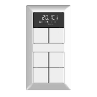
(4) Status LEDs (2 x per control surface for rockers 1...2) (5) Operation LED picture 2: Device components, rear side (6) Connection for KNX/EIB bus cable (7) Connection for pushbutton sensor expansion module Art.-No.: 4093 KRM TS D Page 8 of 241... -
Page 9: Fitting And Electrical Connection
If the pushbutton sensor expansion is used, the adapter frame also has to be mounted on the pushbutton sensor expansion module. Fitting and connecting the continuous controller module picture 3: Fitting the continuous controller module (8) Supporting frame Art.-No.: 4093 KRM TS D Page 9 of 241... - Page 10 Fasten the continuous controller module to supporting frame using the enclosed plastic screws (13). Tighten the plastic screws only lightly. Before mounting the control surfaces (15), load the physical address into the device (see chapter 2.4. Commissioning). Art.-No.: 4093 KRM TS D Page 10 of 241...
- Page 11 (16) Design control surfaces for the expansion module (17) Large supporting frame for combined fitting of continuous controller module and expansion module (18) Pushbutton sensor expansion module (19) Connecting cable for pushbutton sensor expansion module with plug Art.-No.: 4093 KRM TS D Page 11 of 241...
- Page 12 Mount the control surfaces on the pushbutton sensor expansion module (16). Before mounting the control surfaces on the continuous controller module (15), load the physical address into the device (see chapter 2.4. Commissioning). Art.-No.: 4093 KRM TS D Page 12 of 241...
-
Page 13: Commissioning
In programming mode, flashing continues until the operating mode is ended. The state of the LED defined by Programming mode will always prevail. Program the physical address with the help of the ETS. Art.-No.: 4093 KRM TS D Page 13 of 241... - Page 14 To simplify installation, a complete set of buttons is fitted with a mounting spider at the factory. This mounting spider is not essential for installing the decorative control surfaces, meaning that it is not required when adding symbol buttons to the button panel. Art.-No.: 4093 KRM TS D Page 14 of 241...
-
Page 15: Operation
1 & 2. There the button arrangement is fixed (see chapter 2.5.2. Second operating level). Art.-No.: 4093 KRM TS D Page 15 of 241... -
Page 16: Basic Display
(27) Outdoor temperature display i The temperatures can be displayed in °C or alternately in °F. The display format can be configured in common for all temperature values in the ETS. Art.-No.: 4093 KRM TS D Page 16 of 241... -
Page 17: Second Operating Level
Button 1: + change-over or value change in positive direction Button 2: - change-over or value change in negative direction Button 3: n Jump to the previous menu entry Button 4: o Jump to the next menu entry Art.-No.: 4093 KRM TS D Page 17 of 241... - Page 18 °C or °F (parameter-dependent). The basic temperature designates the comfort setpoint temperatures for heating and cooling, depending on the configured operating mode. With "Heating only" it sets the setpoint Art.-No.: 4093 KRM TS D Page 18 of 241...
- Page 19 "Continuous controller" menu. The editing function can be disabled separately. This menu is not accessible in controller extensions. Setting the setpoint temperature "Lowering for night mode, heating" ("Continuous controller" menu): picture 13: Setting the setpoint temperature "Lowering for night mode, heating" Art.-No.: 4093 KRM TS D Page 19 of 241...
- Page 20 ö and Comfort extension óö. In each case, the symbols activated by the Presence operating mode flash. i The comfort extension cannot be activated using the presence function in the second operating level if the frost/heat protection has been activated via the window status! Art.-No.: 4093 KRM TS D Page 20 of 241...
- Page 21 (e.g. via operation of a pushbutton sensor or via communication objects). The menu entry "Operating mode" is visible as an option. This menu is not accessible in controller extensions. Art.-No.: 4093 KRM TS D Page 21 of 241...
- Page 22 Indication of actual temperature: picture 20: Indication of actual temperature Only Indication of the current room temperature No adjustment possibility. The menu entry "Actual temperature" is visible as an option. Indication of setpoint temperature: Art.-No.: 4093 KRM TS D Page 22 of 241...
- Page 23 "Display control" (see page 165-166). The menu item "Display brightness" is always visible. Exiting the second operating level by pressing Save: Art.-No.: 4093 KRM TS D Page 23 of 241...
- Page 24 1 and 3 on the device simultaneously (picture 8). Here the parameter "Save changes after exiting with button combination?" defines whether the settings are saved or not when the second operating level is exited using the button combination. Art.-No.: 4093 KRM TS D Page 24 of 241...
- Page 25 The buttons + or - can then be used to exit the second operating level. In this case the settings are not saved and are discarded! Art.-No.: 4093 KRM TS D Page 25 of 241...
-
Page 26: Technical Data
KNX/EIB supply KNX medium TP 1 Commissioning mode S mode Rated voltage KNX DC 21 V ... 32 V SELV Power consumption KNX typical 150 mW Connection mode KNX Connection terminal Art.-No.: 4093 KRM TS D Page 26 of 241... -
Page 27: Software Description
Up to 3 control surfaces on the continuous controller module for the pushbutton sensor function and for operation of the integrated room temperature controller. Can be expanded to include 4 additional control surfaces using an expansion module. Art.-No.: 4093 KRM TS D Page 27 of 241... -
Page 28: Software "Continuous Controller Module 3Gang 146A11
The controller extension function permits the following settings to operate an external room temperature controller: operating mode change-over with normal and high priority, defined selection of an operating mode, change between different operating modes, change of presence status, setpoint shift. Art.-No.: 4093 KRM TS D Page 28 of 241... - Page 29 Separate or shared command value output in heating and cooling mode. This produces one or two command value objects for each level. Normal or inverted command value output configurable Automatic transmission and cycle time for command value output configurable Art.-No.: 4093 KRM TS D Page 29 of 241...
- Page 30 Full-featured indication of the controller status on the display of the extension (heating / cooling reporting, setpoint shift, room temperature, setpoint temperature and current operating mode). Room temperature measurement also possible on the extension. Art.-No.: 4093 KRM TS D Page 30 of 241...
-
Page 31: Notes On Software
ETS version or later versions are used. The necessary product database is offered in the *.VD4 format. No product database is available for ETS2 and older versions of ETS3. Art.-No.: 4093 KRM TS D Page 31 of 241... -
Page 32: Object Table
3: For reading, the R-flag must be set. The last value written to the object via the bus or by the device will be read. Art.-No.: 4093 KRM TS D Page 32 of 241... - Page 33 3: For reading, the R-flag must be set. The last value written to the object via the bus or by the device will be read. Art.-No.: 4093 KRM TS D Page 33 of 241...
- Page 34 3: For reading, the R-flag must be set. The last value written to the object via the bus or by the device will be read. Art.-No.: 4093 KRM TS D Page 34 of 241...
- Page 35 3: For reading, the R-flag must be set. The last value written to the object via the bus or by the device will be read. Art.-No.: 4093 KRM TS D Page 35 of 241...
- Page 36 4: The number of rockers or buttons depends on the planned device variant. 5: For reading, the R-flag must be set. The last value written to the object via the bus will be read. Art.-No.: 4093 KRM TS D Page 36 of 241...
- Page 37 3: For reading, the R-flag must be set. The last value written to the object via the bus will be read. 4: For reading, the R-flag must be set. The last value written to the object via the bus or by the device will be read. Art.-No.: 4093 KRM TS D Page 37 of 241...
- Page 38 1: For reading, the R-flag must be set. The last value written to the object via the bus or by the device will be read. Art.-No.: 4093 KRM TS D Page 38 of 241...
- Page 39 1-bit object for the transmission of switching telegrams, if 2-channel operation is activated. 1: For reading, the R-flag must be set. The last value written to the object via the bus or by the device will be read. Art.-No.: 4093 KRM TS D Page 39 of 241...
- Page 40 2-byte object for the transmission of value telegrams, if 2-channel operation is activated. 1: For reading, the R-flag must be set. The last value written to the object via the bus or by the device will be read. Art.-No.: 4093 KRM TS D Page 40 of 241...
- Page 41 1: For reading, the R-flag must be set. The last value written to the object via the bus will be read. 2: For reading, the R-flag must be set. The last value written to the object via the bus or by the device will be read. Art.-No.: 4093 KRM TS D Page 41 of 241...
- Page 42 Value object 62 – 1 (decrease level value) 1: For reading, the R-flag must be set. The last value written to the object via the bus or by the device will be read. Art.-No.: 4093 KRM TS D Page 42 of 241...
- Page 43 3: Scene outputs 2 … 8 see scene output 1, shift of the object number (66 + number of scene output - 1). 4: For reading, the R-flag must be set. The last value written to the object via the bus or by the device will be read. Art.-No.: 4093 KRM TS D Page 43 of 241...
- Page 44 1-byte object with which one of the eight internally stored scenes can be recalled or stored again. 1: For reading, the R-flag must be set. The last value written to the object via the bus will be read. Art.-No.: 4093 KRM TS D Page 44 of 241...
-
Page 45: Object Table, Controller Function Section
1: For reading, the R-flag must be set. The last value written to the object via the bus will be read. 2: For reading, the R-flag must be set. The last value written to the object via the bus or by the device will be read. Art.-No.: 4093 KRM TS D Page 45 of 241... - Page 46 4 x 1 bit (parameter-dependent). 1: For reading, the R-flag must be set. The last value written to the object via the bus or by the device will be read. Art.-No.: 4093 KRM TS D Page 46 of 241...
- Page 47 1: For reading, the R-flag must be set. The last value written to the object via the bus or by the device will be read. 2: For reading, the R-flag must be set. The last value written to the object via the bus will be read. Art.-No.: 4093 KRM TS D Page 47 of 241...
- Page 48 1: For reading, the R-flag must be set. The last value written to the object via the bus or by the device will be read. 2: Non-standardised DP type (in accordance with KNX AN 097/07 rev 3). Art.-No.: 4093 KRM TS D Page 48 of 241...
- Page 49 1: For reading, the R-flag must be set. The last value written to the object via the bus or by the device will be read. 2: For reading, the R-flag must be set. The last value written to the object via the bus will be read. Art.-No.: 4093 KRM TS D Page 49 of 241...
- Page 50 The type of feedback control must also be configured to "Switching PI feedback control (PWM)". 1: For reading, the R-flag must be set. The last value written to the object via the bus or by the device will be read. Art.-No.: 4093 KRM TS D Page 50 of 241...
- Page 51 "Switching 2-point feedback control". 1: For reading, the R-flag must be set. The last value written to the object via the bus or by the device will be read. Art.-No.: 4093 KRM TS D Page 51 of 241...
- Page 52 "Continuous PI feedback control". 1: For reading, the R-flag must be set. The last value written to the object via the bus or by the device will be read. Art.-No.: 4093 KRM TS D Page 52 of 241...
- Page 53 "Switching PI feedback control (PWM)". 1: For reading, the R-flag must be set. The last value written to the object via the bus or by the device will be read. Art.-No.: 4093 KRM TS D Page 53 of 241...
- Page 54 1: For reading, the R-flag must be set. The last value written to the object via the bus or by the device will be read. Art.-No.: 4093 KRM TS D Page 54 of 241...
- Page 55 1: For reading, the R-flag must be set. The last value written to the object via the bus or by the device will be read. Art.-No.: 4093 KRM TS D Page 55 of 241...
- Page 56 The value is depicted in a double complement in the positive and negative direction. 1: For reading, the R-flag must be set. The last value written to the object via the bus or by the device will be read. Art.-No.: 4093 KRM TS D Page 56 of 241...
- Page 57 1: For reading, the R-flag must be set. The last value written to the object via the bus will be read. 2: Non-standardised DP type. 3: For reading, the R-flag must be set. The last value written to the object via the bus or by the device will be read. Art.-No.: 4093 KRM TS D Page 57 of 241...
- Page 58 3 x 1 bit and at least three fan levels are enabled (parameter-dependent). 1: For reading, the R-flag must be set. The last value written to the object via the bus or by the device will be read. Art.-No.: 4093 KRM TS D Page 58 of 241...
- Page 59 1-bit object for switching activation of the eighth fan level. This object is only available when the fan control is to take place over 3 x 1 bit and at least eight fan levels are enabled (parameter-dependent). Art.-No.: 4093 KRM TS D Page 59 of 241...
- Page 60 1: For reading, the R-flag must be set. The last value written to the object via the bus will be read. 2: For reading, the R-flag must be set. The last value written to the object via the bus or by the device will be read. Art.-No.: 4093 KRM TS D Page 60 of 241...
- Page 61 "2" = level 2 active, ..., "8" = level 8 active. 1: For reading, the R-flag must be set. The last value written to the object via the bus will be read. Art.-No.: 4093 KRM TS D Page 61 of 241...
-
Page 62: Display Object Table
1: For reading, the R-flag must be set. The last value written to the object via the bus or by the device will be read. 2: For reading, the R-flag must be set. The last value written to the object via the bus will be read. Art.-No.: 4093 KRM TS D Page 62 of 241... - Page 63 This object should be connected to the main controller object with the same function. 1: For reading, the R-flag must be set. The last value written to the object via the bus will be read. Art.-No.: 4093 KRM TS D Page 63 of 241...
- Page 64 This object should be connected to the main controller object with the same function. 1: For reading, the R-flag must be set. The last value written to the object via the bus will be read. Art.-No.: 4093 KRM TS D Page 64 of 241...
- Page 65 "2" = level 2 active, ..., "8" = level 8 active. 1: For reading, the R-flag must be set. The last value written to the object via the bus will be read. 2: Non-standardised DP type. Art.-No.: 4093 KRM TS D Page 65 of 241...
-
Page 66: Functional Description
The control surface next to the display does not have status LEDs. Art.-No.: 4093 KRM TS D Page 66 of 241... - Page 67 "present" for the purpose of general information. The module control surfaces enabled in this manner are displayed and configured in the ETS in the same way as the rockers or buttons of the continuous controller module. Art.-No.: 4093 KRM TS D Page 67 of 241...
- Page 68 The additional parameter pages and the communication objects of the rockers or buttons are then also created and adapted depending on the setting parameterized here. Art.-No.: 4093 KRM TS D Page 68 of 241...
- Page 69 Full-surface operation with rocker function Depending on the basic function of a rocker, it is also possible with some settings to use a press on the full surface with a separate function. Art.-No.: 4093 KRM TS D Page 69 of 241...
- Page 70 (35) First part of the control surface as button with a single actuation point (36) Second part of the control surface as button with a single actuation point (37) Actuation point for button X (X = 1, 3, 5, ...) Art.-No.: 4093 KRM TS D Page 70 of 241...
- Page 71 (left / right) (picture 34). This is also the basic setting of the display control surface. The following illustrations show examples of the button arrangements of the lower control Art.-No.: 4093 KRM TS D Page 71 of 241...
- Page 72 (picture 35). picture 35: Different button configurations in the same push-button sensor i The configuration can still be changed later on. Assigned group addresses or parameter settings remain unaffected by such changes. Art.-No.: 4093 KRM TS D Page 72 of 241...
-
Page 73: Switching" Function
/ or on releasing (ON, OFF, TOGGLE – toggling of the object value). No distinction is made between a brief or long press. The status LEDs can be configured independently (see chapter 4.2.4.1.13. Status LED). Art.-No.: 4093 KRM TS D Page 73 of 241... -
Page 74: Dimming" Function
If the pushbutton sensor is to send the telegram for storing a scene, full-surface actuation must be maintained for more than five seconds. If full-surface actuation ends between the first and the fifth second, the pushbutton sensor will not send any Art.-No.: 4093 KRM TS D Page 74 of 241... - Page 75 If the status LEDs of the rocker are used as "button-press displays", they will light up for three seconds during transmission of the storage telegram. i Full-surface actuation cannot be configured in the push-button functions. Art.-No.: 4093 KRM TS D Page 75 of 241...
-
Page 76: Venetian Blind" Function
If the button is kept depressed longer than T2, the pushbutton sensor transmits no further telegram. The drive remains on until the end position is reached. Art.-No.: 4093 KRM TS D Page 76 of 241... - Page 77 If the button is kept depressed longer than T1, the push-button transmits a long time telegram after the end of T1 for starting the drive. No further telegram is transmitted when the button is released. The drive remains on until the end position is reached. Art.-No.: 4093 KRM TS D Page 77 of 241...
- Page 78 Venetian blind function (short time or long time). If this is not so, even a full-surface operation Art.-No.: 4093 KRM TS D Page 78 of 241...
- Page 79 If the status LEDs of the rocker are used as "button-press displays", they will light up for three seconds during transmission of the storage telegram. i Full-surface actuation cannot be configured in the push-button functions. Art.-No.: 4093 KRM TS D Page 79 of 241...
-
Page 80: Value Transmitter Function
Depending on the setting of the parameter "Value adjustment with overflow", the pushbutton sensor stops the adjustment at this instance or inserts a pause consisting of two levels and then continues the adjustment beginning with the other limiting value. Art.-No.: 4093 KRM TS D Page 80 of 241... - Page 81 Direction of value adjustment = change-over (alternating) Time between two telegrams = 0.5 s Example 1: Value adjustment with overflow? = No picture 40: Example of value adjustment without value range overflow Art.-No.: 4093 KRM TS D Page 81 of 241...
- Page 82 Software "Continuous controller module 3gang 146A11" Functional description Example 2: Value adjustment with overflow? = Yes picture 41: Example of value adjustment with value range overflow Art.-No.: 4093 KRM TS D Page 82 of 241...
-
Page 83: Scene Extension" Function
In case of the rocker function, two different scene numbers can be assigned. The status LEDs can be configured independently (see chapter 4.2.4.1.13. Status LED). Art.-No.: 4093 KRM TS D Page 83 of 241... -
Page 84: Function "2-Channel Operation
The time required for distinguishing between a short and a long operation is defined by the parameter "Time between channel 1 and channel 2". If the button is pressed for less than the Art.-No.: 4093 KRM TS D Page 84 of 241... - Page 85 2- channel function. If this is not so, even a full-surface operation will be interpreted as a wrong operation and not be executed. Art.-No.: 4093 KRM TS D Page 85 of 241...
-
Page 86: Controller Extension" Function
It should be noted that an extension operation is possible with a button configuration. The controller extension function must be enabled in the "Room temperature controller" parameter node. In all other cases, the controller extension function is not operational in the "Pushbutton sensor" function section. Art.-No.: 4093 KRM TS D Page 86 of 241... -
Page 87: Fan Control" Function
It should be noted that fan control is only possible with a button configuration. The fan controller must be enabled in the "Room temperature -> Controller general" parameter node. Otherwise the fan control in the "Pushbutton sensor" function section has no function. Art.-No.: 4093 KRM TS D Page 87 of 241... -
Page 88: Controller Operating Mode" Function
In controller extension operation, the "Controller operating mode" push-button function also has no function. Here, the "Controller extension" push- button function can be used, allowing setting of the operating mode. Art.-No.: 4093 KRM TS D Page 88 of 241... -
Page 89: Setpoint Shift" Function
"Yes". With the setting "No" the temporary indication is inactive, meaning that in case of a setpoint shift only the line graphic is activated, but the temperature value is not also displayed automatically. Art.-No.: 4093 KRM TS D Page 89 of 241... -
Page 90: Change In The Display Reading" Function
The time for the cyclical change of the display can be set in the ETS in the parameter node "Display". Art.-No.: 4093 KRM TS D Page 90 of 241... -
Page 91: Status Led
With the function "2-channel operation" the option "Button-press display" is replaced by "Telegram acknowledge". In this case the status LED is illuminated when both channels are transmitted for about 250 ms each. Art.-No.: 4093 KRM TS D Page 91 of 241... - Page 92 LED. The status LED lights up only if the comparison is "true". i After a device reset, the value of the LED object is always "0". Art.-No.: 4093 KRM TS D Page 92 of 241...
-
Page 93: Disabling Function
(rocker X.1 or X.2) will be used. The telegrams are transmitted to the bus via the required communication object of the target button. The following table shows all possible telegram reactions of the pushbutton sensor with respect to the target push-button function. Art.-No.: 4093 KRM TS D Page 93 of 241... - Page 94 The status LEDs of the disabled buttons are without function (no button-press display either). Only the "Always ON" or "Always OFF" state remains unaffected by the disabling function. Art.-No.: 4093 KRM TS D Page 94 of 241...
- Page 95 It is first necessary to release all buttons before a new push-button function can be executed if so permitted by the state of disabling. Art.-No.: 4093 KRM TS D Page 95 of 241...
-
Page 96: Transmission Delay
The transmit delay is not active for the rocker and push-button functions of the pushbutton sensor. In addition, the controller objects are not influenced by the transmission delay. Art.-No.: 4093 KRM TS D Page 96 of 241... -
Page 97: Alarm Message
ETS. i An active alarm message is not stored so that the alarm indication is generally deactivated after a reset or after programming with the ETS. Art.-No.: 4093 KRM TS D Page 97 of 241... -
Page 98: Room Temperature Controller
(see chapter 4.2.4.2.4. Operating mode change-over), the room temperature controller will automatically decide whether heating or cooling energy is required and calculates the command value for the heating or cooling system. Art.-No.: 4093 KRM TS D Page 98 of 241... - Page 99 For this reason, you should, if possible, not set the deadband (temperature difference between the setpoint temperatures for the comfort heating and cooling modes) below the default value (2 K). Art.-No.: 4093 KRM TS D Page 99 of 241...
- Page 100 "Room temperature control -> Command value and status output" parameter branch. The control algorithm controls the signal objects. Please note that the command value is recalculated every 30 s, followed by an updating of the signal objects. Art.-No.: 4093 KRM TS D Page 100 of 241...
-
Page 101: Control Algorithms And Calculation Of Command Values
The command values calculated by the control algorithm are output via the "Heating command value" or "Cooling command value" communication objects. Depending on the control algorithm Art.-No.: 4093 KRM TS D Page 101 of 241... - Page 102 "Cycle time of the switching command value…" parameter in the "Room Art.-No.: 4093 KRM TS D Page 102 of 241...
- Page 103 If different actuators with different adjusting cycle times are used, take account of the longest of the times. Always note the information given by the manufacturers of the actuators. Art.-No.: 4093 KRM TS D Page 103 of 241...
- Page 104 The room temperature is also evaluated by this type of control in cycles every 30 seconds. Thus the command values change, if required, only at these times. The disadvantage of a Art.-No.: 4093 KRM TS D Page 104 of 241...
- Page 105 "Heating" (picture 47) or "Cooling" (picture 48). The images take two temperature setpoints, one-stage heating or cooling and non-inverted command value output. picture 47: 2-point feedback control for the single "Heating" operating mode Art.-No.: 4093 KRM TS D Page 105 of 241...
- Page 106 ETS for 2-point feedback control, although they have no function. The following two images show 2-point feedback control for the mixed operating mode "Heating Art.-No.: 4093 KRM TS D Page 106 of 241...
- Page 107 An additional 2-point feedback control heating or cooling level works exactly the same as the 2- point feedback control of the basic level. The difference is that the setpoint and the hysteresis values will shift by taking into account the configured level offset. Art.-No.: 4093 KRM TS D Page 107 of 241...
-
Page 108: Adapting The Control Algorithms
If the "Type of heating" or "Type of cooling" parameters are set to "Via control parameters" it will be possible to adjust the control parameter manually. The feedback control may be Art.-No.: 4093 KRM TS D Page 108 of 241... - Page 109 : Short reset time Fast compensation of control deviations (ambient conditions), risk of permanent oscillations : Long reset time Slow compensation of control deviations Table 5: Effects of the settings for the control parameters Art.-No.: 4093 KRM TS D Page 109 of 241...
- Page 110 A small hysteresis will lead to small temperature variations but to a higher bus load. A large hysteresis switches less frequently but will cause uncomfortable temperature variations. picture 52: Effects of the hysteresis on the switching behaviour of the command value of 2-point feedback control Art.-No.: 4093 KRM TS D Page 110 of 241...
-
Page 111: Operating Mode Change-Over
The activated comfort extension option will be indicated on the display by the combination of the óõ or óö symbols. i You can assign an own temperature setpoint to the "Heating" or "Cooling" operating modes for each operating mode. Art.-No.: 4093 KRM TS D Page 111 of 241... - Page 112 Change-over of the operating mode using KNX/EIB communication objects A distinction is made whether the operating modes should be changed over via separate 1-bit objects or, alternatively, by the 1-byte KONNEX objects. Art.-No.: 4093 KRM TS D Page 112 of 241...
- Page 113 Table 6 also shows the status of the communication objects and the resulting operating mode. picture 53: Operating mode change-over through 4 x 1-bit objects with presence button picture 54: Operating mode change-over through 4 x 1-bit objects with motion detector Art.-No.: 4093 KRM TS D Page 113 of 241...
- Page 114 (second operating level, button as controller operation). An operating mode set by an object can therefore be shifted by an operating mode change-over on the device, if no higher-priority mode (e.g. window contact / motion detector) is activated. Art.-No.: 4093 KRM TS D Page 114 of 241...
- Page 115 (see page 118-119). Table 7 also shows the status of the communication objects and the resulting operating mode. picture 55: Operating mode change-over through KONNEX object with presence button Art.-No.: 4093 KRM TS D Page 115 of 241...
- Page 116 Comfort mode Standby mode Night mode Frost/heat protection Comfort mode Comfort mode Comfort ex- tension Comfort ex- tension Comfort mode Standby mode Night mode Frost/heat protection Comfort mode Frost/heat protection Art.-No.: 4093 KRM TS D Page 116 of 241...
- Page 117 (forced object -> "00"). The controller therefore automatically resets the status of the presence button when an object value is received via the operating mode objects or the forced object is reset. Art.-No.: 4093 KRM TS D Page 117 of 241...
- Page 118 The room temperature controller offers various options to change over into the Frost/heat protection mode. In addition to the change-over by the corresponding operating mode change- over object, a window contact can activate frost/heat protection. With these options, the window Art.-No.: 4093 KRM TS D Page 118 of 241...
- Page 119 "Night operation" -> The night mode will be activated after the initialisation phase. "Frost/heat protection operation" -> The frost/heat protection mode will be activated after the initialisation phase. The objects associated with the activated operating mode will be updated after a reset. Art.-No.: 4093 KRM TS D Page 119 of 241...
-
Page 120: Temperature Setpoints
The possible range of values for a setpoint temperature lies between + 7.0 °C and + 99.9 °C for "heating" and is bounded by the frost protection temperature in the lower range. The level offset configured in ETS will be additionally considered in a two-level heating mode (picture 58). Art.-No.: 4093 KRM TS D Page 120 of 241... - Page 121 The setpoint temperatures for Comfort, Standby and Night mode exist in this operating mode and the heat protection temperature can be preset (picture 59). The following applies… ≤ T Comfort setpoint cooling Standby setpoint cooling ≤ T Comfort setpoint cooling Night setpoint cooling Art.-No.: 4093 KRM TS D Page 121 of 241...
- Page 122 ≤ T Comfort setpoint basic level heating Comfort setpoint additional level heating ≤ T Night setpoint basic level heating Night setpoint additional level heating ≤ T Comfort setpoint cooling Night setpoint cooling Art.-No.: 4093 KRM TS D Page 122 of 241...
- Page 123 Software "Continuous controller module 3gang 146A11" Functional description Setpoints for the "heating and cooling" operating mode picture 61: Setpoint temperatures in the operating mode "Heating and cooling" with symmetrical deadband (recommended specification) Art.-No.: 4093 KRM TS D Page 123 of 241...
- Page 124 + 7 °C and + 45.0 °C and is bounded by the frost protection temperature in the lower range and by the heat protection temperature in the upper range. The level offset configured in ETS will be additionally considered in a two-level heating or cooling mode. Art.-No.: 4093 KRM TS D Page 124 of 241...
- Page 125 63: Setpoint temperatures in the operating mode "Basic and additional heating and cooling" with symmetrical deadband (recommended specification) picture 64: Setpoint temperatures in the operating mode "Basic and additional heating and cooling" with asymmetrical deadband (recommended specification) Art.-No.: 4093 KRM TS D Page 125 of 241...
- Page 126 KNX/EIB communication objects. The "Frost/heat protection" operating mode allows the separate configuration of two temperature setpoints for heating (frost protection) and cooling (heat protection) solely in the Art.-No.: 4093 KRM TS D Page 126 of 241...
- Page 127 Night mode in the same way. i The automatic setpoint temperature raising by the setpoint temperature limit goes only as far as the configured heat protection temperature. Therefore the heat protection temperature can never be exceeded. Art.-No.: 4093 KRM TS D Page 127 of 241...
- Page 128 ETS. The 2-byte object "Basic setpoint" provides the option of changing the basic temperature, and thus all the dependent setpoint temperatures 'at a later date'. Art.-No.: 4093 KRM TS D Page 128 of 241...
- Page 129 With local control in the second operating level, it must be taken into account that temperature changes that have been made are only saved to the device when this is provided for in the ETS configuration. Art.-No.: 4093 KRM TS D Page 129 of 241...
- Page 130 A positive shift is possible up to the configured heat protection temperature. A negative shift is possible up to the set frost protection temperature. Art.-No.: 4093 KRM TS D Page 130 of 241...
- Page 131 The controller monitors the received value independently. As soon as the external preset value exceeds the limits of the adjustment options for the setpoint shift in positive or negative direction, the controller will correct the received value and adjust the Art.-No.: 4093 KRM TS D Page 131 of 241...
- Page 132 After that the display switches over to the next piece of display information. The setpoint shift is then only shown via the line graphic, and no longer as a temperature value, even in case of further button-presses. Art.-No.: 4093 KRM TS D Page 132 of 241...
- Page 133 Following the return of bus voltage or after re-programming via the ETS, the object value will be initialised according to the current setpoint temperature value and actively transmitted to the bus. Art.-No.: 4093 KRM TS D Page 133 of 241...
-
Page 134: Room Temperature Measurement
Adjustment becomes necessary, for example, if the temperature measured by the sensors stays permanently below or above the actual temperature in the vicinity of the sensor. To determine the temperature deviation, the Art.-No.: 4093 KRM TS D Page 134 of 241... - Page 135 "Actual temperature, unadjusted" and, for example, be displayed in visualisations. The object for the unadjusted temperature is updated and transmitted at the same times as the "Actual temperature" object. Art.-No.: 4093 KRM TS D Page 135 of 241...
- Page 136 Poor parameterisation of the limit temperature (limit temperature near to the room/setpoint temperature) means that it is possible that the specified setpoint temperature for the room can never be reached! Art.-No.: 4093 KRM TS D Page 136 of 241...
-
Page 137: Command Value And Status Output
-> Inverted: Command value 0 % ... 100 %, value 255 ... 0 For switching command values: -> Not inverted: Command value off / on, value 0 / 1 -> Inverted: Command value off / on, value 1 / 0 Art.-No.: 4093 KRM TS D Page 137 of 241... - Page 138 (cycle time in the controller is preferably to be configured smaller). The "0" setting will deactivate the periodic transmission of the command value. Art.-No.: 4093 KRM TS D Page 138 of 241...
- Page 139 Controller inactive (deadband) Controller active Frost alarm Frost alarm No frost alarm ≤ +5 °C) (TRoom > +5 °C / +41 °F) Room Table 9: Meaning of the 1-bit single status signals Art.-No.: 4093 KRM TS D Page 139 of 241...
- Page 140 Upon a reset, the additional status object will be updated after the initialisation phase. After this, the status will be updated cyclically every 30 seconds in parallel with the command value calculation of the controller command values. Art.-No.: 4093 KRM TS D Page 140 of 241...
-
Page 141: Fan Controller
Often the technical information for a fan coil unit specifies change-over times that the fan controller must Art.-No.: 4093 KRM TS D Page 141 of 241... - Page 142 Reading out is possible. i After a device reset, the fan level objects and the visualisation object are updated and the status transmitted to the bus. Art.-No.: 4093 KRM TS D Page 142 of 241...
- Page 143 Manual operation: With the local control of a button configured to "Function = Fan control" and "Button function = Manual control" on the device, the controller makes a distinction as to Art.-No.: 4093 KRM TS D Page 143 of 241...
- Page 144 ETS should be configured to higher values (possible time range 100 ms ... 25.5 s). It should be noted that the waiting time is also taken into account on each level change-over in automatic operation (see page 141-142). Art.-No.: 4093 KRM TS D Page 144 of 241...
- Page 145 In this case the switching sequence of the individual levels and the waiting time configured in the ETS are also taken into account in the level change-over. The limitation level can be one of the available fan levels. Art.-No.: 4093 KRM TS D Page 145 of 241...
- Page 146 The command value to be evaluated for the fan controller can be influenced by the "Command value is 0% until internal command value is greater than" parameter in the lower command value range. The fan controller only evaluates the command value according to the configured Art.-No.: 4093 KRM TS D Page 146 of 241...
- Page 147 For reasons of safety, fan protection is not carried out with an active forced position. i If fan run-on times are configured in the ETS, then the fan is switched off after a delay when fan protection is deactivated. Art.-No.: 4093 KRM TS D Page 147 of 241...
-
Page 148: Disable Functions Of The Room Temperature Controller
"0" while the basic level continues to operate. i A disable is always deleted after a reset (return of bus voltage, ETS programming operation). Art.-No.: 4093 KRM TS D Page 148 of 241... -
Page 149: Valve Protection
However, the clock continues to run internally with the deviation to be expected. This means that the valve protection time may shift continually with an unsynchronised clock. Art.-No.: 4093 KRM TS D Page 149 of 241... -
Page 150: Room Temperature Controller Extension
As the displayed states and information and also some operating functions are strongly dependent on the parameterisation of the main controller, the controller extension must also be configured and thus match the functions of the main controller. These Art.-No.: 4093 KRM TS D Page 150 of 241... - Page 151 Display of the heating symbol. controller extension Command value Command value for for heating heating D.Input R.Output Display of the cooling symbol. controller extension Command value Command value for for cooling cooling Art.-No.: 4093 KRM TS D Page 151 of 241...
- Page 152 The actual room temperature can be detected by the communication objects of the room temperature measurement system, which are also available in the controller extension, and then shown in the display. Art.-No.: 4093 KRM TS D Page 152 of 241...
-
Page 153: Operating Functions
In order to ensure that the object value transmitted in the "Presence TOGGLE" setting is always the correct one, the presence object of the room temperature controller and the "Presence Art.-No.: 4093 KRM TS D Page 153 of 241... - Page 154 The information for the step value as feedback from the controller enables the extension to continue the adjustment anytime at the right point. The extension units can likewise react to a reset of the setpoint shifting function by the controller. Art.-No.: 4093 KRM TS D Page 154 of 241...
-
Page 155: Display Functions
This is indicated by the " â " symbol for heating or by the " è " symbol for cooling. For the indication to function, the communication objects for the controller command values of Art.-No.: 4093 KRM TS D Page 155 of 241... - Page 156 The fan level display must be enabled separately on the controller extension using the "Controller fan control available" parameter. In addition, it is necessary to set with how many fan levels (1...8) the main controller works. Art.-No.: 4093 KRM TS D Page 156 of 241...
-
Page 157: Room Temperature Measurement
"Room temperature controller" (see chapter 4.2.4.2.6. Room temperature measurement). Art.-No.: 4093 KRM TS D Page 157 of 241... -
Page 158: Behaviour After A Device Restart
For larger KNX/EIB installations, where the extensions are sometimes distributed over several lines, the remaining lines should also be initialised after a reset of one line. Art.-No.: 4093 KRM TS D Page 158 of 241... -
Page 159: Light Scene Function
"Discussion" scene. In this example, the parameter "Permit transmission ?" in the parameter node of a scene output can be set to "No" for the "Discussion" scene. The scene output is then deactivated during the corresponding scene. Art.-No.: 4093 KRM TS D Page 159 of 241... - Page 160 This should be done only for one actuator out of an actuator group so that the value response is Art.-No.: 4093 KRM TS D Page 160 of 241...
- Page 161 Recalling scenes in the course of a storage process is not possible, the buttons or rockers of the pushbutton sensor remain nevertheless operational. Art.-No.: 4093 KRM TS D Page 161 of 241...
-
Page 162: Display
Indication of the basic setpoint in the positive "0 - - - -" or negative "- - - - 0" direction. A bar corresponds to shifting by one level value. The value of a level can be parameterised ---- in the ETS. If no shift is active, only "0" is displayed. Art.-No.: 4093 KRM TS D Page 162 of 241... - Page 163 The information is shown separately on the display. It is possible to change over between the information automatically after set times or in a controlled manner by pressing a button on the device (picture 7). picture 66: Possible display information of the display (24) Time display Art.-No.: 4093 KRM TS D Page 163 of 241...
- Page 164 ETS, the version of the device firmware is shown in the display (e.g. "F1.00") and the operation LED flashes. Art.-No.: 4093 KRM TS D Page 164 of 241...
-
Page 165: Display Control
= " 0" It is not possible to switch-off backlighting switched on by operation early using a bus telegram. Art.-No.: 4093 KRM TS D Page 165 of 241... - Page 166 The next piece of information is displayed when this time has elapsed. When the last piece of information has been reached, there is a changeover to the first piece of information. Art.-No.: 4093 KRM TS D Page 166 of 241...
- Page 167 The piece of display information last called up by the cyclical change or by a button press is overridden and overwritten in the display if the device is operated locally in another way (e. g. temporary setpoint temperature display in the case of setpoint shift, second operating level). Art.-No.: 4093 KRM TS D Page 167 of 241...
-
Page 168: Delivery State
In the un-programmed delivery state of the device or in the case of an application program loaded via the ETS, the version of the device firmware is shown in the display (e.g. "F1.00"). The display brightness is set to the initial brightness (70%). Art.-No.: 4093 KRM TS D Page 168 of 241... -
Page 169: Parameters
LED can display different states by means of other flashing rates. These comprise Programming mode, the confirmation of full-surface actuation or the message that an application has not been loaded. Art.-No.: 4093 KRM TS D Page 169 of 241... - Page 170 ETS. In order to avoid the unintentional disruption of essential functions, access to the entire second operating level can Art.-No.: 4093 KRM TS D Page 170 of 241...
- Page 171 Visible controller can be set in the second display operating level ("Visible" setting). With the setting "Hidden", it is not possible to set the operating mode in the second operating level. Art.-No.: 4093 KRM TS D Page 171 of 241...
- Page 172 ("Visible" setting). With the setting "Hidden", the outdoor temperature is not displayed in the second operating level. This can then be configured only if needed in the basic display ("Display" parameter node). Art.-No.: 4093 KRM TS D Page 172 of 241...
- Page 173 Save changes after This parameter defines whether the exiting with button settings are saved or not when the combination? second operating level is exited using the button combination. Art.-No.: 4093 KRM TS D Page 173 of 241...
-
Page 174: Parameter For Room Temperature Measurement
(0...255) * 1 min; the "0" setting, the external sensor is not 0 = inactive automatically polled by the controller. In this case, the sensor must transmit its temperature value itself. Art.-No.: 4093 KRM TS D Page 174 of 241... - Page 175 This parameter specifies whether and room temperature when the determined room temperature (0...255) * 1 min; 0 = of the first control circuit is to be inactive periodically output via the "Actual temperature" object. Art.-No.: 4093 KRM TS D Page 175 of 241...
-
Page 176: Parameters On The Pushbutton Sensor Function Section
/ it is to be divided horizontally or button pairs of the vertically. This defines the actuation points of the control surface. Art.-No.: 4093 KRM TS D Page 176 of 241... - Page 177 Venetian blind Depending on this choice, the ETS 1-byte value transmitter displays different communication objects 2-byte value transmitter and parameters for this rocker. Scene extension 2-channel operation Art.-No.: 4093 KRM TS D Page 177 of 241...
- Page 178 100 … 400 … 50000 This parameter defines how long the top and dimming, rocker 1.1 (or left-hand) rocker must be pressed for (100 … 50000 x 1 ms) the pushbutton sensor to send a Art.-No.: 4093 KRM TS D Page 178 of 241...
- Page 179 Time between two 200 ms This parameter defines the interval at telegrams 300 ms which the dimming telegrams are 400 ms automatically repeated in the telegram 500 ms repetition mode. Only visible if Art.-No.: 4093 KRM TS D Page 179 of 241...
- Page 180 Rocker X.2:TOGGLE interlinked for a correct change of the running direction. Operation concept short – long – short For Venetian blind control, four different operation concepts can be selected. For Art.-No.: 4093 KRM TS D Page 180 of 241...
- Page 181 (less than 1 s), a sustained press (longer than 5 s) and an invalid button-press (between 1 s and 5 s). A brief press Art.-No.: 4093 KRM TS D Page 181 of 241...
- Page 182 Depending on the "Button arrangement" (0 … 255) parameter, this parameter defines the object value when the bottom (or right- hand) rocker is pressed. Only visible if "Function = … 0…255"! Art.-No.: 4093 KRM TS D Page 182 of 241...
- Page 183 Level size (1 … 15) 1...15 In a value adjustment, the pushbutton sensor determines the new telegram value from the previous value and the preset level size. If the value falls below Art.-No.: 4093 KRM TS D Page 183 of 241...
- Page 184 Depending on the "Button arrangement" … 40 °C) parameter, this parameter defines the Rocker 1.1 object value when the top (or left-hand) rocker is pressed. Only visible if "Function = Temperature value transmitter"! Art.-No.: 4093 KRM TS D Page 184 of 241...
- Page 185 Same as value after last long button-press = enabled"! adjustment In the setting "Same as parameterised value", after each long press the Same as value from pushbutton sensor always starts with the Art.-No.: 4093 KRM TS D Page 185 of 241...
- Page 186 Time between two 0.5 s This parameter defines the interval at telegrams which the pushbutton sensor transmits new telegrams during a value adjustment. Only visible if "Value adjustment by long button-press = enabled"! Art.-No.: 4093 KRM TS D Page 186 of 241...
- Page 187 18.001 "Scene Rocker 1.2 Control" can recall or store up to 64 scenes by their numbers. The parameter defines the scene number to be transmitted when the bottom (or right) of Art.-No.: 4093 KRM TS D Page 187 of 241...
- Page 188 (or right-hand) rocker is pressed. Only visible if "Function channel 1 (2) = Switching (1 bit)"! 0...255 This parameter defines the object value transmitted to the bus when the top (or Art.-No.: 4093 KRM TS D Page 188 of 241...
- Page 189 (1 … 255 x 100 ms) transmits the telegram for channel 1 and the telegram for channel 2 when the bottom (or right side) of the rocker is pressed. Art.-No.: 4093 KRM TS D Page 189 of 241...
- Page 190 Depending on this setting, the ETS Venetian blind displays different communication objects 1-byte value transmitter and parameters for this button. 2-byte value transmitter Scene extension 2-channel operation Controller extension Fan controller Change in the display Art.-No.: 4093 KRM TS D Page 190 of 241...
- Page 191 25 % the configured level. 50 % Especially with smaller dimming levels it 100 % is advisable for the pushbutton sensor to repeat the dimming telegrams automatically (see "telegram repetition"). Art.-No.: 4093 KRM TS D Page 191 of 241...
- Page 192 – long – short For Venetian blind control, four different operation concepts can be selected. For long – short these concepts, the ETS shows further parameters. short – long Long – short or short Art.-No.: 4093 KRM TS D Page 192 of 241...
- Page 193 In the setting "Same as value after last adjustment", after a long press the pushbutton sensor starts with the value transmitted by itself or by another device with this group address as the last value. Art.-No.: 4093 KRM TS D Page 193 of 241...
- Page 194 Thereafter, the pushbutton sensor transmits a telegram with the value of the other range limit and continues the value adjustment in the same direction. Art.-No.: 4093 KRM TS D Page 194 of 241...
- Page 195 In the setting "Same as value from communication object", after a long Art.-No.: 4093 KRM TS D Page 195 of 241...
- Page 196 (setting "No") and if the pushbutton sensor reaches the lower limit of the adjustment range (0°C, 0 lux, 0) or the upper limit (40°C, 1500 lux, 65535) during value adjustment, the Art.-No.: 4093 KRM TS D Page 196 of 241...
- Page 197 "Channel 1 or channel 2" is selected, the pushbutton sensor decides dependent on the button-press duration which of the channels will be used. If the setting "Channel 1 and channel 2" is selected, the pushbutton sensor Art.-No.: 4093 KRM TS D Page 197 of 241...
- Page 198 Forced oper. mode change- presence state or change the current over room temperature value. With regard to the setting of this parameter, the ETS Presence button setpoint shows further parameters. Art.-No.: 4093 KRM TS D Page 198 of 241...
- Page 199 Presence ON presence state of the room temperature controller in a defined way or change Presence TOGGLE over between the two states ("Presence Art.-No.: 4093 KRM TS D Page 199 of 241...
- Page 200 If the fan is in the highest level, then pressing a button switches it back to the OFF level. From there, every additional Art.-No.: 4093 KRM TS D Page 200 of 241...
- Page 201 On the other hand it is possible to activate the Presence function ("Presence button" setting). The Presence function allows activation of Comfort mode or a comfort extension on the internal controller. Art.-No.: 4093 KRM TS D Page 201 of 241...
- Page 202 (With the rocker function, the parameters for the left and right status LED are separate and configurable). Always ON Irrespective of the pushbutton or rocker function, the status LED is switched on permanently. Art.-No.: 4093 KRM TS D Page 202 of 241...
- Page 203 The LED is off if the presence function is inactive. This setting can only be configured in the push-button function "Controller extension" and with the push-button function "Presence button". Art.-No.: 4093 KRM TS D Page 203 of 241...
- Page 204 In addition, the received 0 = LED static OFF switching telegram can be evaluated in such a way that the LED flashes. 1 = LED static OFF / 0 = LED flashes Art.-No.: 4093 KRM TS D Page 204 of 241...
- Page 205 -128 ... 0 ... 127 This parameter defines the reference (-128 … 127) value to which the value of the "Status LED" object is compared. h Pushbutton sensor -> Disable Disabling function? Art.-No.: 4093 KRM TS D Page 205 of 241...
- Page 206 If the pushbutton sensor is to perform Button 2 the function of a specific button at the … beginning of the disabling state, this Module button 14 (if button will be selected here. present) Art.-No.: 4093 KRM TS D Page 206 of 241...
- Page 207 Reaction as button >>Y<< This function can... when released correspond to the function assigned to any of the buttons in the non-disabled Art.-No.: 4093 KRM TS D Page 207 of 241...
- Page 208 Button 1 ? The user can specify for each button separately whether it will be affected by Button 2 ? the disabling function during the disabling state. … Module button 14 (if present) Art.-No.: 4093 KRM TS D Page 208 of 241...
- Page 209 A telegram can, for instance, be sent via this object to the "Alarm message" objects of other pushbutton sensors in order to reset the alarm status there as well (observe the polarity of the Art.-No.: 4093 KRM TS D Page 209 of 241...
- Page 210 Acknowledge alarm OFF telegram This parameter sets the polarity of the message by ON telegram "Alarm message acknowledge" object. This parameter presetting depends on the selected polarity of the alarm message object. Art.-No.: 4093 KRM TS D Page 210 of 241...
-
Page 211: Parameter For The Controller Function Section
As on the main controller, various items of status information of the temperature controller can be shown on the device display. As the displayed states and information and also some operating functions are Art.-No.: 4093 KRM TS D Page 211 of 241... - Page 212 1.0 K 1.5 K 2.0 K h Room temperature control -> Controller general Controller operating Heating The room temperature controller mode distinguishes between two different Cooling operating modes. The operating modes Art.-No.: 4093 KRM TS D Page 212 of 241...
- Page 213 Basic heating and possible to use the basic and additional additional cooling levels simultaneously for a fan controller within an operating mode. Basic cooling and This basic setting of this parameter Art.-No.: 4093 KRM TS D Page 213 of 241...
- Page 214 (10 ... 127) * 0.1 K This parameter is only visible if "Type of heating = via control parameter" and the heating control type "PI feedback control". 0...50...255 Art.-No.: 4093 KRM TS D Page 214 of 241...
- Page 215 (0 ... 255) * 1 min; 0 = control parameter. inactive This parameter is only visible if "Type of cooling = via control parameter" and the cooling control type "PI feedback control". Art.-No.: 4093 KRM TS D Page 215 of 241...
- Page 216 The preset operating mode for after the operating mode after Cooling return of the bus voltage is specified reset Operating mode before here. reset Only visible if "Change-over between heating and cooling = via object"! Art.-No.: 4093 KRM TS D Page 216 of 241...
- Page 217 If the command value sinks below a threshold value, minus the configured hysteresis, then the change-over takes place into the next lowest fan level. Art.-No.: 4093 KRM TS D Page 217 of 241...
- Page 218 If a higher limit level is configured, then the limit has no effect. Art.-No.: 4093 KRM TS D Page 218 of 241...
- Page 219 "Heating" (if necessary, in the basic and additional levels). Cooling fan run-on time, 0...255 If the fan is switched-off in automatic or *0.1 s, 0=Inactive manual operation, it runs on for the time Art.-No.: 4093 KRM TS D Page 219 of 241...
- Page 220 Command value offset, 0... 100 The command value evaluated by the fan controller in Automatic mode can be Art.-No.: 4093 KRM TS D Page 220 of 241...
- Page 221 Normal (under current, normally or in inverted form. this means opened) This parameter is only visible if the operating mode "Heating" or "Heating and cooling" is configured along with two-level operation. Art.-No.: 4093 KRM TS D Page 221 of 241...
- Page 222 The "Yes" setting here enables the message function for cooling. Controller status No status The controller can output its current operating status. A distinction is made Art.-No.: 4093 KRM TS D Page 222 of 241...
- Page 223 In the "No" setting, the basic setpoint shift carried out is in effect for only as long as the operating mode or heating/ cooling mode has not changed or the basic setpoint is maintained. Otherwise Art.-No.: 4093 KRM TS D Page 223 of 241...
- Page 224 The comfort setpoint temperatures for Asymmetrical "Heating and cooling" operating modes are derived from the basic setpoint in consideration of the adjusted deadband. The deadband (temperature zone for which there is neither heating nor Art.-No.: 4093 KRM TS D Page 224 of 241...
- Page 225 "Setpoint (0...255) * 0.1 K temperature" object. In the "0" setting, the setpoint temperature is not transmitted automatically when there is a change. Art.-No.: 4093 KRM TS D Page 225 of 241...
- Page 226 (if necessary with additional levels). Raise the setpoint 0...20...127 The value by which the standby setpoint temperature during temperature for cooling is lowered Standby operating compared to the cooling comfort temperature. Art.-No.: 4093 KRM TS D Page 226 of 241...
- Page 227 Comfort, Standby and Night modes, which are greater than the maximum setpoints configured in the ETS. The maximum temperature setpoint is specified by the "Max. setpoint temperature in cooling Art.-No.: 4093 KRM TS D Page 227 of 241...
- Page 228 "Max. setpoint temperature and difference to outdoor temperature". Max. setpoint 20°C...26°C...35°C This parameter defines the maximum temperature in cooling setpoint temperature in Comfort mode operation with an active setpoint temperature limit. Art.-No.: 4093 KRM TS D Page 228 of 241...
- Page 229 Here it is possible to specify whether the temperature during Enabled setpoint temperature of the "Night" night mode (heating) operating mode for heating mode can be changed in the menu of the second Art.-No.: 4093 KRM TS D Page 229 of 241...
- Page 230 Night or Frost/heat protection mode. In this case, the operating mode will not be changed, although the presence function has been activated. This parameter is only visible when presence detection is configured to "Presence button". Art.-No.: 4093 KRM TS D Page 230 of 241...
- Page 231 Either the basic level or to the additional level for heating can be limited. This parameter can only be set in two- level control operation. Art.-No.: 4093 KRM TS D Page 231 of 241...
- Page 232 The 1 K hysteresis is fixed and cannot be changed. Art.-No.: 4093 KRM TS D Page 232 of 241...
-
Page 233: Parameters For The Display
ETS or specified locally in the second operating level. In addition, the lighting can also be switched or dimmed by the communication objects, independently of operation on the Art.-No.: 4093 KRM TS D Page 233 of 241... - Page 234 If the pictogram frames are displayed ("Yes" setting), then the frames are always visible and the active symbols are illuminated inside the corresponding frames. Art.-No.: 4093 KRM TS D Page 234 of 241...
- Page 235 Indicated on the Setpoint temperature display. This parameter presetting depends on Actual temperature the selected display information. Outdoor temperature h Display -> Indications 2, 3, 4 (see Indication 1) Art.-No.: 4093 KRM TS D Page 235 of 241...
-
Page 236: Parameter On Scene Function
This parameter serves to specify the extension number of the fifth scene. 1...6 ... 64 Art.-No.: 4093 KRM TS D Page 236 of 241... - Page 237 "Yes". Scene 1 If the state of an actuator group is to Allow transmission? remain unchanged during the recall of a scene, this parameter can be set to Art.-No.: 4093 KRM TS D Page 237 of 241...
- Page 238 Scenes 2 … 8 see scene 1! h Scene output 2 ... 8 (see Scene output 1) Art.-No.: 4093 KRM TS D Page 238 of 241...
-
Page 239: Appendix
Fan level limit ........145 status LEDs ........15-16 Fan protection ........147 Storing scenes ........160 Fitting ............. 9 Switching PI feedback control ....102 Art.-No.: 4093 KRM TS D Page 239 of 241... - Page 240 Switch-on level ........144 Symbols ..........162 temperature setpoints ......130 Underfloor heating temperature limit ..136 Valve protection ........149 window status ........118 Art.-No.: 4093 KRM TS D Page 240 of 241...
- Page 241 Appendix ALBRECHT JUNG GMBH & CO. KG Volmestraße 1 D-58579 Schalksmühle Telefon: +49.23 55.8 06-0 Telefax: +49.23 55.8 06-1 89 E-mail: mail.info@jung.de Internet: www.jung.de www.jung-katalog.de Art.-No.: 4093 KRM TS D Page 241 of 241...
Need help?
Do you have a question about the 4093 KRM TS D and is the answer not in the manual?
Questions and answers