FAAC 750 Manual
Hydraulic swing gate operator
Hide thumbs
Also See for 750:
- Installation manual (29 pages) ,
- Instruction manual (14 pages) ,
- User manual (4 pages)
Table of Contents
Advertisement
Advertisement
Table of Contents

Related Manuals for FAAC 750


Summary of Contents for FAAC 750
- Page 1 Hydraulic Swing Gate Operator FAAC International Inc. FAAC International Inc. Headquarter & East Coast Operations West Coast Operations 3160 Murrell Road 357 South Acacia Avenue Rockledge, FL 32955 Fullerton, CA 92831 Tel. 800 221 8278 www.faacusa.com...
-
Page 2: Table Of Contents
12. Operating Modes Detailed Description 2.5. Air Bleed Operations 13. Prewired Enclosure 2.5. Installing The Gate SPARE PARTS 3. FINAL OPERATIONS Hydraulic Drive Unit 3.1. Adjusting the By-Pass Valves Hydraulic Control Unit 4. MANUAL OPERATION 5. MAINTENANCE 750 732028 RevB US... -
Page 3: Important Safety Information
Guarding is supplied for exposed rollers. IMPORTANT SAFETY INFORMATION The operator instructions shall list the maximum number of open and close entrapment protection devices capable of being connected to the operator. WARNING - to reduce the risk of severe injury or death: b) The operator is intended for installation only on gates used READ AND FOLLOW ALL INSTRUCTIONS. -
Page 4: General Safety Precautions
GENERAL SAFETY PRECAUTIONS For gate operators that utilize a contact sensor (edge sensor or similar): One or more contact sensors shall be located where Gate Construction the risk of entrapment or obstruction exists, such as at Vehicular gates should be constructed and installed in the leading edge, trailing edge, and postmounted both accordance with ASTM F2200: Standard Specification for inside and outside of a vehicular horizontal slide gate. -
Page 5: Ul325 Gate Operator Classifications
Installing the Warning Signs This FAAC swing gate operator is supplied with two warning signs to alert people that a possible hazard exists and that appropriate actions should be taken to avoid the hazard or to reduce exposure to it. -
Page 6: 750 Operator
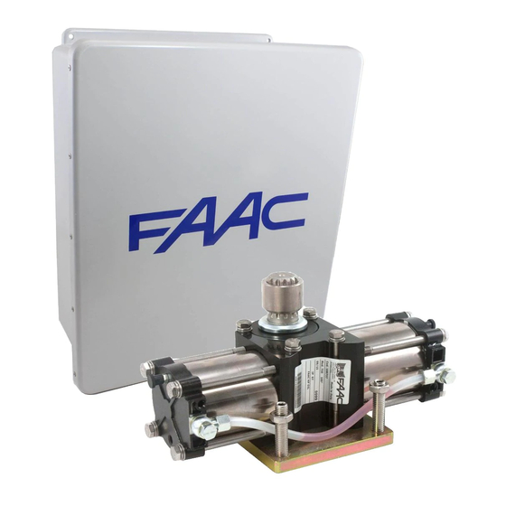
750 OPERATOR The 750 is an automatic gate operator for a swinging gate leaf. It makes possible to automate gates in a virtually invisible way The operator is a two piece unit consisting of a hydraulic control unit (pump) and a hydraulic drive unit which are connected by the means of two hydraulic hoses. -
Page 7: Installation
2.1 PRELIMINARY CHECKS 1) Dig a foundation hole as shown in fig.4. Before you install the 750 Operator, you must insure that the gate leaf meets the following criteria.: To avoid having to create holes at the base of the post, •... -
Page 8: Installing The Hydraulic Control Unit
1 ¼ 4) Install a 1-1/4" PVC conduit for the hydraulic lines that reaches the hydraulic control unit (fig.6). The path of the conduit must have wide bends to facilitate the routing of the hydraulic lines (fig.7). 5) Place the drive unit on the foundation plate as shown in fig. 5/a-b, and ensure that it is not resting on the levelling set screws (fig.2 - ref.7). -
Page 9: Hydraulic Connection
3/16" The control unit fitting beside the green by-pass screw must 2.4 HYDRAULIC CONNECTION be connected to the drive unit fitting that is within the property The drive unit and hydraulic control unit are connected by two (fig.12-ref.B). The control unit fitting beside the red by-pass screw hydraulic lines, each with an outside diameter of 5/16 in. -
Page 10: Air Bleed Operations
(fig.15). Top up oil using only FAAC HP OIL. Top up the oil level using the references on the oil filler cap rod (fig.20). The provided FAAC HP OIL can fill a path of approximately 6 ft in length. For longer paths, complete filling use only FAAC HP OIL. -
Page 11: Installing The Gate
2.6 INSTALLING THE GATE 1) Manual release the system (see paragraph 4). 2) Turn the splined bushing (while on the splined shaft) in the closing direction until it stops. 3) To prevent the piston in the drive unit from bottoming out in its cylinder turn the splined shaft 5 degrees in the opening direction 4) Make the gate leaf shoe: - Construc the U-shaped section of the shoe as shown in... -
Page 12: Final Operations
3. FINAL OPERATIONS 3.1. ADJUSTING THE BYPASS VALVES The 750 operators features a built in anti-crushing system that guarantees to stop the gate movement in the presence of an obstacle. The anti-crushing system is adjusted using two bypass valves, one for the opening movement and one for the closing.. - Page 13 This page is intentionally left blank...
-
Page 14: 455D Control Board
Semi-automatic B / Dead-man C Opening/Closing Time: Connector J2 - Rapid Connection to RP Receivers Programmable (from 0 to 120 s) The 5 pin J2 connector allows to plug in the FAAC RP radio Pause Time: receivers Programmable (from 0 to 4 min.) Closing Leaf Delay: Programmable (from 0 to 4 min.) -
Page 15: Electric Connections
5. Electric Connections VAC MAX. 24 V DC 230 VAC LIMIT-SWITCHES 115 VAC 60 Hz For connection OPEN A of the safety 12 V AC devices, see the OPEN B Maglock next paragraph STOP Note: Capacitors are supplied with the operator or the prewired enclosure OP FSW - Opening safety devices contact (N.C.): Terminal Block J4 - Motors and Warning Lamp The opening safety input is used to protect the leaf move-... -
Page 16: Connection Of Safety Devices
To comply with the UL325 standard for gate operators every entrapment zone, as defined in ASTMF2200, must be pro- ADVANCED PROGRAMMING tected by two independent entrapment protection devices. One of the devices is inherent in the FAAC operators or the Display Function Default control board design, the other can be external, like a pho- tocell or an edge sensor. - Page 17 Only one monitored photocell can be connected to the See the following connections diagrams for example of Closing or Opening safety inputs. More than one photocell opening/closing safety wiring. or other device can be connected to the safety inputs, but they will not be monitored.
-
Page 18: Operating Logics
7. Operating Logics The following table displays the sequence of functions This is a brief description of the main operating logics of the accessible in BASIC PROGRAMMING: system. For a complete description please refer to Table 3 • E (semi-automatic): This mode requires a command to BASIC PROGRAMMING press open and a command to close. - Page 19 Display Function Default Advanced Programming: INDICATOR-LIGHT: To access ADVANCED PROGRAMMING, press and hold key F and then press key +: : the output functions as a standard indicator- light (ON at opening and pause, flashing at • Release key +, the unit displays the name of the first closing, and OFF when gate is closed).
-
Page 20: Start-Up
9. Start-up Rotation direction and force check: 1. Program the functions of the 455 D control board ac- LED Indicators: cording to need, as previously shown. The board has a two-digit display. When not in 2. Turn power off to the control board. “PROGRAMMING”... -
Page 21: Learning Operating Times
11. Final Tests 10. Learning Operating Times Once programming is complete and the proper operating WARNING: During the learning procedure, safety times are stored in the board’s memory perform a devices are disabled! Avoid crossing the leaf complete test the system. Verify that the operator(s) run properly and, most importantly, check that force is movement area when this operation is carried out. -
Page 22: Operating Modes Detailed Description
12. Operating Modes Detailed Description (1) If maintained, it prolongs the pause until disabled by the command (timer function) (2) If a new pulse occurs within 2 seconds after reversing, it immediately stops operation. (3) During the partial opening cycle, an OPEN A pulse causes total opening. NB.: Effects on other active pulse inputs in brackets. - Page 23 (1) If maintained, it prolongs the pause until disabled by the command (timer function) (2) If a new pulse occurs within 2 seconds after reversing, it immediately stops operation. (3) During the partial opening cycle, an OPEN A pulse causes total opening. NB.: Effects on other active pulse inputs in brackets.
-
Page 24: Prewired Enclosure
13. Prewired Enclosure The 455D board can be easily installed in a prewired enclosure supplied by FAAC that integrates a number of functions: Power ON-OFF switch and accessory power outlet, loop detector sockets prewired to the board, large terminal strips to easily connect activations, accessories and safeties. - Page 25 230 V AC Power Wiring Guidelines 115 V Check local wiring codes in all cases and follow all local building codes. Wiring and hookup should be performed by qualified electricians/installers only. AC power should be supplied from a circuit breaker panel and must have its own dedicated circuit breaker.
- Page 26 Maglock. The Maglock kit can be ordered separately as an accessory. Refer to this schematic for the connections. If using non-FAAC relay make sure the minimum switch volt- age is less than 12Vac 24 VDC...
- Page 27 This page is intentionally left blank...
-
Page 28: Hydraulic Drive Unit
Hydraulic drive unit Part Part Number Description Part Part Number Description 701384 Bolt M 10x25 7011085 Bolt 750 Drive Body 8 x 100 mm 7094375 Bonded Seal Washer 703108 Lock Washer 7092025 Piston Ring 7366245 Cylinder 750 Drive 100 Degree... -
Page 29: Hydraulic Control Unit
7039285 Washer 706122 Pin Pump 4x28 mm 7110115 Fitting 7090010015 O-Ring 4.48 x 1.78 mm 390700 Banjo Bolt Kit 7090030015 O-Ringr 6.75 x 1.78 mm 2170.1 Seal Kit Pump Unit 7290155 Manual Release Lever 714019 Qt.1 FAAC Oil: 1 qt. - Page 30 NOTES: _________________________________________________________________________________________ _________________________________________________________________________________________ _________________________________________________________________________________________ _________________________________________________________________________________________ _________________________________________________________________________________________ _________________________________________________________________________________________ _________________________________________________________________________________________ _________________________________________________________________________________________ _________________________________________________________________________________________ _________________________________________________________________________________________ _________________________________________________________________________________________ _________________________________________________________________________________________ _________________________________________________________________________________________ _________________________________________________________________________________________ _________________________________________________________________________________________ _________________________________________________________________________________________ _________________________________________________________________________________________...
- Page 31 FAAC S.p.A. and operated. or FAAC International, Inc. The warranty herein above set forth shall not be deemed to cover FAAC International, Inc.’s obligations under...
- Page 32 750 - 732028 - Rev.B - US © 2018, FAAC International, Inc. - All Rights Reserved Published in July. 2018...
Need help?
Do you have a question about the 750 and is the answer not in the manual?
Questions and answers