FAAC 400 User Manual
Hydraulic swing gate operator
Hide thumbs
Also See for 400:
- Instruction manual (32 pages) ,
- Installation manual (24 pages) ,
- Manual (32 pages)
Table of Contents
Advertisement
Quick Links
Advertisement
Table of Contents

Related Manuals for FAAC 400


Summary of Contents for FAAC 400
- Page 1 Hydraulic Swing Gate Operator UL325 Compliant FAAC International Inc. FAAC International Inc. Headquarter & East Coast Operations West Coast Operations 3160 Murrell Road 357 South Acacia Avenue Rockledge, FL 32955 Fullerton, CA 92831 Tel. 800 221 8278 www.faacusa.com...
-
Page 2: Table Of Contents
5. MANUAL OPERATION 5.1 Restoring Normal Operating Mode 6. OUTWARD OPENING 7. POSITIVE STOP ACCESSORY 8. MAINTENANCE AND REPAIRS 8.1 Oil Level Check 9. SPARE PARTS 400 CBAC Cylinder Locking Cap Rear Flange 455D CONTROL BOARD 1. General Description 2. Technical Specification 3. -
Page 3: Important Safety Information
• Use only FAAC MSE MO, CN60 or M60 edge sensors. • All exposed pinch points are eliminated or guarded. •... -
Page 4: Ul325 Gate Operator Classifications
Installing the Warning Signs This FAAC swing gate operator is supplied with two warning signs to alert people that a possible hazard exists and that appropriate actions should be taken to avoid the hazard or to reduce exposure to it. -
Page 5: Description Technical Specifications
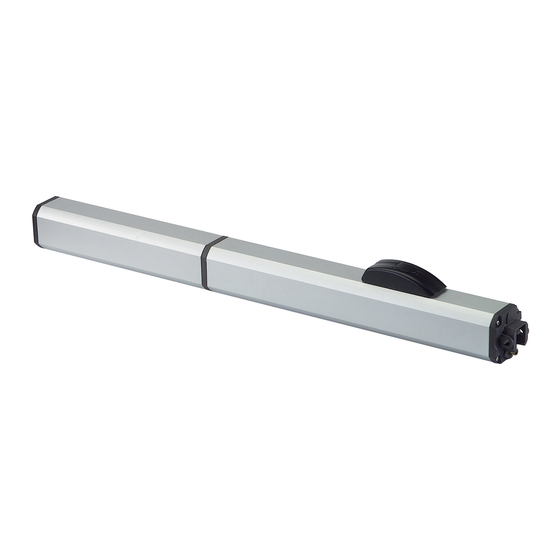
400 OPERATOR 1.1 DIMENSIONS 1 DESCRIPTION AND TECHNICAL SPECIFICATIONS The FAAC Model 400 Swing Gate Operator consists of an electric pump and a hydraulic piston which transmits drive Figure 2 to the gate leaf. Models with hydraulic locking do not require the installation of electric locks, as they provide mechanical locking of the leaf when the motor is not operating. -
Page 6: Installation
2 INSTALLATION 2.3 GENERAL RULES 2.1 PRELIMINARY CHECKS If the dimensions indicated in table A or B cannot be achieved, the following must be considered in order to To ensure a correctly operating automated system, the calculate different measurements: structure of the gate must satisfy the following requirements: •... - Page 7 Secure the operator to the rear attachment with the supplied screws (Fig. 6). Figure 8 Screw, halfway down, the front attachment onto the rod (Fig. 8, Ref.1). Tighten with the supplied nut. Release the operator (see Section 5). Fully extend the rod out to its stopping point, then push it back approximately 1/4 inch (Fig.
-
Page 8: By-Pass Valves Adjustment
15.) Connect the power cable to the operator and fasten the screws (Figure 14A). 2.5 BY-PASS VALVES ADJUSTMENT The Model 400 has an anti-crushing safety device which limits the operator’s force when an obstacle is encountered while the gate is moving. Follow these steps to adjust the intervention... -
Page 9: System Test
6 OUTWARD OPENING 4 SYSTEM TEST Refer to Table C for this particular application. Select the When you have finished installing the unit, run a functional operator according to leaf length as detailed in Table 1. check of the automated system and all accessories con- Installation dimensions are provided in Table C. -
Page 10: Positive Stop Accessory
7 POSITIVE STOP ACCESSORY With the use of the proper square shaped swivel joint (sup- plied): In case the gate doesn’t have built in mechanical stops, it is possible to install, directly on the operator, an accessory to limit the rod’s travel in both directions. (P/N: 490109 STANDARD, 490043 EG) It’s possible to limit the rod’s travel and create two solid mechanical stop positions. -
Page 11: Maintenance And Repairs
• Now look into the body of the machine and to the left, the fluid should be up to the center of the tie rod (top for 400 standard or center for 400 EG when the piston is fully retracted) •... -
Page 12: Spare Parts
115V 1400 RPM Motor 7272115 Protective Cover (EG) 7119485 Vibration Dampener 3900985 Skin Pack: 400 7161825 Operator Body 400 3900975 Skin Pack: 400 (EG) 7161835 Operator Body (EG) 2167.1 Seal Kit 7320065 Vent Screw Label 714019 Qt.1 FAAC Oil: 1 qt. 7182175 Long Pin 7140251 Qt.1... -
Page 13: Cylinder
Cylinder Part Part Number Description Part Part Number Description 4994625 Front Flange 7049135 Valve Retainer 701829 Front Flange Bolt (M5 x 20 mm) 70900500 O-Ring (10.82 x 1.78mm) 63000315 Seal Front Flange (Internal) 4404065 Inlet Valve 7090360025 O-Ring (Distribution flange) 7049005 Retainer (Brass) 4404085... -
Page 14: Locking Cap
Locking Cap Part Part Number Description 2151 Knob Screw (ss) 4mm x 8mm 7290445 Manual Release Knob w/ screw 701526 Screw (ss) 4 x 10mm 720344 Locking Cap Base 729043 Lock 7090290015 O-Ring (Lock Cylinder) 7275285 Top Cover 7131005 Key (Viro) 7275275 Cover, Key 7090855... -
Page 15: Rear Flange
Rear Flange Part Part Number Description 7171485 Rear Flange 417010 Wiring Harness 63001005 Cable With Molded Connector 7090895 O-Ring 21x2 mm 7110015 Oil Plug 7109135 Cable Strain Relief 701479 Screw 3 x 12mm 701466 SCREW 3 x 8 mm 7090905 O-Ring 14 x 1.5 mm... -
Page 16: 455D Control Board
Semi-automatic B / Dead-man C Opening/Closing Time: Connector J2 - Rapid Connection to RP Receivers Programmable (from 0 to 120 s) The 5 pin J2 connector allows to plug in the FAAC RP radio Pause Time: receivers Programmable (from 0 to 4 min.) Closing Leaf Delay: Programmable (from 0 to 4 min.) -
Page 17: Electric Connections
5. Electric Connections VAC MAX. 24 V DC 230 VAC 50 Hz LIMIT-SWITCHES 115 VAC For connection 60 Hz OPEN A of the safety 12 V AC devices, see the OPEN B Maglock next paragraph STOP NB: Capacitors are supplied with the operator. OP FSW - Opening safety devices contact (N.C.): Terminal Block J4 - Motors and Warning Lamp The opening safety input is used to protect the leaf move-... -
Page 18: Connection Of Safety Devices
STP CL OP LOCK +24V W.L. OPEN One of the devices is inherent in the FAAC operators or the control board design, the other can be external, like a pho- tocell or an edge sensor. RX OP TX OP See this picture for the photocells positioning: -TX FSW 16”... - Page 19 Connection of One Pair of Closing Photocells Connection of Two Pairs of Closing Photocells, One (monitored), One Pair of Opening Photocells Monitored and One non Monitored (monitored) and One pair of Opening/Closing Photocells (non monitored) 9 10 11 12 13 14 15 16 17 18 19 20 21 B STP CL OP LOCK...
-
Page 20: Operating Logics
7. Operating Logics The following table displays the sequence of functions This is a brief description of the main operating logics of the accessible in BASIC PROGRAMMING: system. For a complete description please refer to Table 3 • A (automatic): The gate opens on command and BASIC PROGRAMMING press automatically closes after a pause phase. - Page 21 Display Function Default Advanced Programming: INDICATOR-LIGHT: To access ADVANCED PROGRAMMING, press and hold key F and then press key +: is selected, the output functions as a standard indicator-light (lighted at opening and • Release key +, the unit displays the name of the first pause, flashing at closing, and off when gate is function.
-
Page 22: Start-Up
(red and black wires) on the 455 D control board. 7. Check force setting of the motors, modify if necessary. Note: For hydraulic operators, like the 400, force should be programmed to maximum level (50) 8. Stop leaf movement with a STOP command. -
Page 23: Final Tests
- SIMPLE LEARNING (Without Slow Down): 11. Final Tests Check that the leaves are closed. Enter “BASIC PROGRAMMING,” select the TIME LEARNING function and Once programming is complete and the proper operating then press the + push-button for 1 second. The display times are stored in the board’s memory perform a begins flashing and the leaves begin to open. -
Page 24: Operating Modes Detailed Description
12. Operating Modes Detailed Description (1) If maintained, it prolongs the pause until disabled by the command (timer function) (2) If a new pulse occurs within 2 seconds after reversing, it immediately stops operation. (3) During the partial opening cycle, an OPEN A pulse causes total opening. NB.: Effects on other active pulse inputs in brackets. - Page 25 (1) If maintained, it prolongs the pause until disabled by the command (timer function) (2) If a new pulse occurs within 2 seconds after reversing, it immediately stops operation. (3) During the partial opening cycle, an OPEN A pulse causes total opening. NB.: Effects on other active pulse inputs in brackets.
-
Page 26: Prewired Enclosure A12
13. Prewired Enclosure The 455D board can be easily installed in a prewired enclosure supplied by FAAC that integrates a number of functions: Power ON-OFF switch and accessory power outlet, loop detector sockets prewired to the board, large terminal strips to easily connect activations, accessories and safeties. - Page 27 AC Power Wiring Guidelines 230 V Check local wiring codes in all cases and follow all 115 V local building codes. Wiring and hookup should be performed by qualified electricians/installers only. AC power should be supplied from a circuit breaker panel and must have its own dedicated circuit breaker.
- Page 28 Maglock. The Maglock kit can be ordered separately as an accessory. Refer to this schematic for the connections. If using non-FAAC relay make sure the minimum switch volt- age is less than 12Vac 24 VDC...
- Page 29 Shadow Loop kit option The prewired enclosure comes with dedicated terminal blocks for the connection of a relay and a loop detector socket to implement the shadow loop functionality. The Shadow loop kit can be ordered separately as an acces- sory.
-
Page 30: Limited Warranty A16
FAAC S.p.A. and operated. or FAAC International, Inc. The warranty herein above set forth shall not be deemed to cover FAAC International, Inc.’s obligations under...
Need help?
Do you have a question about the 400 and is the answer not in the manual?
Questions and answers