FAAC 400 Installation Manual
Hide thumbs
Also See for 400:
- Instruction manual (32 pages) ,
- User manual (30 pages) ,
- Installation manual (12 pages)
Table of Contents

Related Manuals for FAAC 400


Summary of Contents for FAAC 400
-
Page 1: Table Of Contents
Check the Motor's Direction of Rotation Connect Other Devices Set Operating Controls Fine-Tune the Pressure Adjustments Bleed the Operator Maintenance The 400 Operator FAAC International, Inc. The Control Panel 303 Lexington Avenue Troubleshooting Cheyenne, WY 82007 Exploded View, 400 CBAC www.faacusa.com... -
Page 2: Important Safety Information
Important Safety Information Both the installer and the owner and/or operator of this system need to read and understand this installation manual and the safety instructions supplied with other components of the gate system. This information should be retained by the owner and/or operator of the gate. WARNING! Gate Design To reduce the risk of injury or death... - Page 3 Refer to the label on your operator 8. To guarantee the efficiency of this equipment, the manu system. facturer recommends that qualified personnel periodically check and maintain the equipment. U.L. Class and FAAC Operator Model Duty Cycle Typical Use Class I: Residential Vehicular Gate Operator...
-
Page 4: Technical Data
U.L. recognized installation. The 450 MPS can control panel, refer to the label on the transformer of the be used to control a single 400 operator or a dual (biparting) control panel: system. Both the control panel and the operator must use the same power supply voltage. -
Page 5: Unpacking The Operator
2 Protective Cover - 1 each 3 Protective Cover Tie Rods - 2 each 4 Protective Cover End Cap - 1 each When you receive your 400 Operator, complete the 5 Rear mounting bracket - 1 each following steps. 6 Rear mounting plate (use is optional) - 1 each 7 Short brass pin with 8mm nut and washer - 1 each Inspect the shipping box for physical damage. -
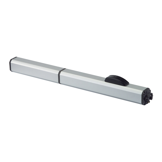
Page 6: The 400 Operator
The 400 Operator can be used to swing the gate leaf inward 450 MPS Logic Modes or outward. Most versions provide hydraulic locking in at least one position, either opened or closed, depending on how it was ordered. - Page 7 A (Automatic) Logic (450 MPS) Gate Open A Open B Stop Opening Closing Warning Status Reversing Reversing Light Device(s) Device(s) Closed Opens both leaves Opens single leaf No effect No effect No effect and closes them connected to after pause time Motor 1 and closes it after pause time...
- Page 8 E (Semi-automatic) Logic (450 MPS) Gate Status Open A Open B Stop Opening Closing Warning Reversing Reversing Light Device(s) Device(s) Closed Opens Opens single No effect No effect No effect both leaves leaf connected to Motor 1 Opening Stops Stops Stops Stops;...
-
Page 9: Installation Instructions
The installation tasks discussed in this man- ual are tasks particular to the 400 Operator. Prepare the Gate Before you install the 400 Operator, you need to prepare the gate itself for the operator. Be sure to do the following three things: 1. -
Page 10: Attach The Mounting Hardware
** For A, B, and D , if you choose one of these values with two asterisks, then you must choose the other values with two asterisks. Figure 4. Important mounting dimensions for inward-swinging 400 operators, top view Attach the Mounting Hardware... -
Page 11: Attach The Operator To The Gate
27 9/16 (70) no limit MUST be less than A Figure 5. Important mounting dimensions for outward swinging 400 operators, top view Note: Clamping the front mounting bracket at the marked Note: Lubricating the threads of the protective cover tie rods... -
Page 12: Install The 450 Mps Control Panel
Figure 7 shows a basic layout for a Using a Junction Box two-leaf gate with two 400 Operators. Connecting your operator(s) to the control panel may require Installing the control panel consists of the following general the use of one or more junction boxes. -
Page 13: Check The Motor's Direction Of Rotation
1 Operator 2 Control Panel 3 Photocell Wire Gauges for Given Voltage 4 Switch 220 VAC 115 VAC 5 Junction box (see text) A 2 x 18 AWG A 2 x 18 AWG 6 Reversing edges B 4 x 14 AWG B 4 x 14 AWG 7 Gate stops C 5 x 18 AWG... - Page 14 1 J1 terminal block for main power supply 8 Leaf delay potentiometer 2 J2 terminal block for connecting the operator(s) 9 DIP switch assembly 3 J3 terminal block for low-voltage accessories Fuses 220 VAC 115 VAC 4 J4 quick connector port 10 F1, Main power 10 A 5 Pressure adjustment potentiometer...
- Page 15 NOTE: In order to comply with UL 325, two sets of FAAC photocells must be installed. One set should be 6 inches outside the closed gate(s) and act as a closing reversing device. Another set should be 6 inches beyond the swing of the gate and act as an opening reversing device.
-
Page 16: Connect Other Devices
5. A reversing stroke is a short closing phase that allows the electric lock time to disengage itself before the operator starts Decoder Card: If you are installing a FAAC radio receiver, a its opening. Turn DIP switch 5 on only if necessary for your Digicard magnetic card reader, or a Digikey keypad, use the lock to function correctly. - Page 17 Figure 11. Common accessories wired to 450 MPS.
-
Page 18: Set Operating Controls
4 potentiometers that control a wide range of functions. Torque: The torque potentiometer on the 450 MPS must be turned all the way clockwise for the 400 Operator. The poten- Set DIP Switches tiometer controls voltage to the operator. It is used for the FAAC model 412, a screw drive operator. -
Page 19: Fine-Tune The Pressure Adjustments
You fine tune the pressures for both opening and closing after you have installed the control panel for the 400 Operator. Figure 16. The brass key assembly in relation to the black... -
Page 20: Bleed The Operator
Bleed the Operator Air bubbles in hydraulic fluid cause erratic performance in a hydraulic system, so you must rid the 400 Operator of that air to insure smooth operation. If you have removed the vent screw, the 400 operator should bleed itself. - Page 21 Problem: The gate does not respond to model of operator. For example, because the 400 CBAC has an activating signal. a rated opening time of 17 sec, you should set the time at 19 or 20 seconds.
- Page 23 This page intentioanly blank...
-
Page 24: 303 Lexington Avenue Cheyenne, Wy 82007
FAAC S.p.A. or FAAC International, Inc., assumes nor authorizes any person to assume for them any other liabili- ty in connection with the sale or use of the products of FAAC S.p.A. or FAAC International, Inc. The warranty hereinabove set forth shall not be deemed to cover maintenance parts, including, but not limited to, hydraulic oil, filters, or the like.
Need help?
Do you have a question about the 400 and is the answer not in the manual?
Questions and answers