FAAC 400 Instruction Manual
Hydraulic swing gate operator
Hide thumbs
Also See for 400:
- Instruction manual (32 pages) ,
- User manual (30 pages) ,
- Installation manual (24 pages)
Table of Contents
Advertisement
UL325 Compliant
FAAC International Inc.
Headquarter & East Coast Operations
5151 Sunbeam Road
Suites 9-11
Jacksonville, FL 32257
Tel. 866 925 3222
www.faacusa.com
400
Hydraulic Swing Gate Operator
FAAC International Inc.
West Coast Operations
357 South Acacia Avenue
Unit 357
Fullerton, CA 92831
Tel. 800 221 8278
Advertisement
Table of Contents
Troubleshooting

Related Manuals for FAAC 400


Summary of Contents for FAAC 400
- Page 1 Hydraulic Swing Gate Operator UL325 Compliant FAAC International Inc. FAAC International Inc. West Coast Operations Headquarter & East Coast Operations 357 South Acacia Avenue 5151 Sunbeam Road Unit 357 Suites 9-11 Fullerton, CA 92831 Jacksonville, FL 32257 Tel. 800 221 8278 Tel.
-
Page 3: Table Of Contents
General Safety Precautions UL325 Gate Operator Classifications Installing the Warning Signs 1. TECHNICAL SPECIFICATIONS Dimensions 2. WIRING 3. INSTALLING THE MODEL 400 3.1. Preliminary Checks 3.2. Installation Dimensions 3.3 General Rules for Determining Installation Dimensions 3.4. Installing the Operator 4. START-UP Anti-Crushing System Adjustments 5. - Page 4 16. POWER AND ACCESSORIES CONNECTIONS AC Power Wiring Guidelines AC Power Connection Magnetic Lock Connection 17. TROUBLESHOOTING LIMITED WARRANTY Read this instruction manual before you begin installing the product. = Information regarding personal safety and proper maintanence of the product. = Information regarding the product’s characteristics or operation.
-
Page 5: Important Safety Information
• Use only FAAC “Photobeam” photoelectric eyes to comply with UL325. For gate operators that utilize a contact sensor (edge sensor or similar):... -
Page 6: General Safety Precautions
• It is extremely unsafe to compensate for a damaged • Use only FAAC MSE MO, CN60 or M60 edge gate by increasing hydraulic pressure. sensors. • Install devices such as reversing edges and photo beams to provide better protection for personal property and pedestrians. -
Page 7: Ul325 Gate Operator Classifications
Installing the Warning Signs This FAAC swing gate operator is supplied with two warning signs to alert people that a possible hazard exists and that appropriate actions should be taken to avoid the hazard or to reduce exposure to it. -
Page 8: Technical Specifications
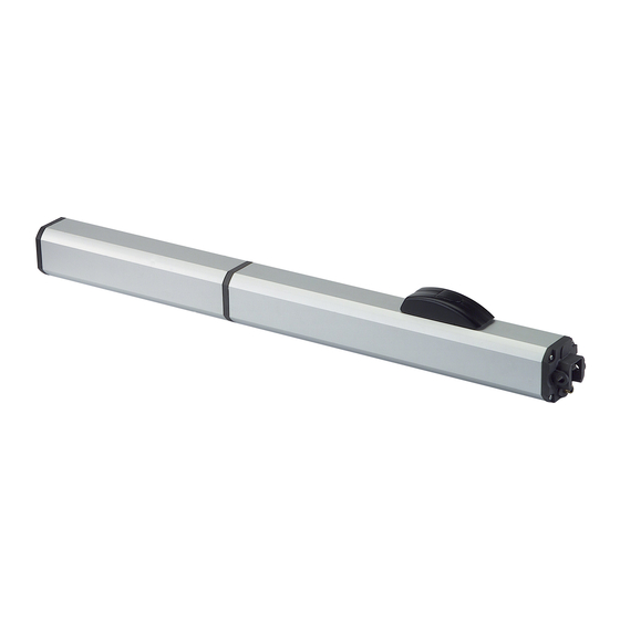
MODEL 400 OPERATOR These instructions apply to the following models: Dimensions 400 CBC, 400 CBAC, 400 SB, 400 SBS, 400 CBACR, 400 CBAC EG, 400 SB EG. Figure 2 The FAAC Model 400 Swing Gate Operator consists of an electric pump and a hydraulic piston which transmits drive to the gate leaf. -
Page 9: Installing The Model 400
3.3 General Rules for Determining Installation 3. INSTALLING THE MODEL 400 Dimensions If the dimensions indicated in table A or B cannot be 3.1. Preliminary Checks achieved, the following must be considered in order to calculate different measurements: To ensure a correctly operating automated system, the struc- ture of the gate must satisfy the following requirements: •... - Page 10 Figure 8 Secure the operator to the rear attachment with the supplied screws (Fig. 6). Screw, halfway down, the front attachment onto the rod (Fig. 8, Ref.1). Tighten with the supplied nut. Release the operator (see Section 7). Figure 6 11.) Temporarily release the operator from the bracket and then permanently weld the bracket to the leaf.
-
Page 11: Start-Up
(Figure 14A). Anti-Crushing System Adjustments Figure 14 The Model 400 has an anti-crushing safety device which limits the operator’s force when an obstacle is encountered while the gate is moving. To adjust the intervention threshold of the anti-crushing system, temporarily open the release cover. -
Page 12: System Test
9. SPECIAL APPLICATIONS FOR SWING 6. SYSTEM TEST LEAF GATES When you have finished installing the unit, run a functional check of the automated system and all ac- cessories connected to it, especially safety devices. Opening Outward, with Operator Installed Explain to the client the correct operation and use of Inside the operator and indicate potentially dangerous areas... -
Page 13: Positive Stop Accessory
10. POSITIVE STOP ACCESSORY In case the gate doesn’t allow you to have built in mechanical stops, it is possible to install, directly on the operator, an accessory to limit the rod’s travel in both With the use of the proper square shaped swivel joint directions. -
Page 14: Maintenance And Repairs
Safety devices installed on the system must be checked every 6 months. For repairs, contact FAAC’s authorized repair centers. FA A C 4 00 Hy d r a u l i c S w i n g Gat e O pe r at or... -
Page 15: Exploded Views
702003 HEX NUT (4 MM) 7272105 PROTECTIVE COVER 7700205 MOTOR 220V 4P. 3900985 SKINPACK 400 7119485 VIBRATION DAMPENER 2167+ SEAL KIT 400 7161825 400 OPERATOR TANK 7320065 VENT SCREW LABEL 714017 FAAC HP OIL LT.1 7182175 LONG PIN 44** 2707 8 μF CAPACITOR... -
Page 16: Cylinder
Cylinder POS. DESCRIPTION POS. DESCRIPTION 7049135 RETAINING RING NUT 701829 TORX M5X20 INOX SCREW 7090050015 GASKET O-RING 10.82X1.78 63000315 FRONT FLANGE BUSHING 7090360025 GASKET O-RING 40.95X2.62 4404065 INLET VALVE WITH SPRING 7090815 D-RING 7049005 RETAINER 7094505 GUIDE RING 4404085 LOCK VALVE IN ZAMACK 7361335 RETRACT TUBE 4994655... -
Page 17: Locking Cap
Locking Cap POS. DESCRIPTION POS. DESCRIPTION 701307 SCREW 4X8 STAINLESS STEEL 7090855 O-RING 33.05X1.78 7290445 RELEASE KNOB 722795 BASE SUPPORT FOR RELEASE 701526 TORX 4X10 STAINLESS STEEL 7090865 O-RING 41X1.78 720344 TOP COVER 718358 BY-PASS EXTENSIONS 729043 LOCK LEVER 718359 ACTIVATION EXTENSIONS 7090895 21x2 O-RING... -
Page 18: Rear Flange
Rear Flange POS. DESCRIPTION POS. DESCRIPTION 7171485 BACK FLANGE 7109135 STRAIN RELIEF 417010 WIRING HARNESS 701479 SCREW 3X12 63001005 MOULDED CABLE KIT 701466 SCREW M3X8 7090895 21X2 O-RING 7090725 O-RING 14X1.5 7110015 PLUG FA A C 4 00 Hy d r a u l i c S w i n g Gat e O pe r at or... -
Page 19: Control Board
13.4. 455 D Layout and Components 13. 455 D CONTROL BOARD 13.1 455 D Control Board Warnings FSWOP FCA1 OP_A FCC1 STOP FCC2 OP_B Important: Before attempting any work on the control FSWCL FCA2 board (connections, maintenance), always turn off –... - Page 20 (walls, etc) against the closing areas against the risk of impact. risk of impact and crushing. FAAC recommends use of the lay-out in Fig. D (in the event of fixed obstacles at opening) or in Fig. E (no fixed obstacles).
- Page 21 Connection of ONE Pair of Opening Photocells Connection of TWO Pairs of Closing Photocells 9 10 11 12 13 14 15 16 17 18 19 20 21 9 10 11 12 13 14 15 16 17 18 19 20 21 B STP CL OP LOCK CL OP...
- Page 22 13.4.6 Connector J2 - Rapid Connection to RP 13.4.4 Terminal Block J1 - Accessories (Fig. B) Receivers OPEN A - “Total Opening” Command (N.O.): This is used for rapid connection to RP receivers (see Fig. Any pulse generator (push-button, detector, etc.) which, by closing Q).
-
Page 23: Programming
GRAMMING” mode. Programming is split into two parts: BASIC and and closing limit-switches or Gatecoders ADVANCED. The 400 operator cannot use limit switches but only 13.5.1 Basic Programming Gatecoders. They are used to detect the leaf’s angular To access BASIC PROGRAMMING, press key F:... - Page 24 Display Function Default 13.5.2 Advanced Programming INDICATOR-LIGHT: To access ADVANCED PROGRAMMING, press and hold is selected, the output functions as a key F and then press key +: standard indicator-light (lighted at opening and • Release key +, the unit displays the name of the first function. pause, flashing at closing, and off when gate is •...
-
Page 25: Start-Up
+ push-button for 1 second: the display begins flashing and the leaves begin the opening movement. N.B: For hydraulic operators, like the 400, force should be pro- grammed to maximum level (50) The movement stops automatically when the opening stop limit is 8. -
Page 26: System Test
1° OPEN - Leaf 1 slows down at opening (it stops automatically on reaching the stop limit) 2° OPEN - Leaf 2 opening movement begins 3° OPEN - Leaf 2 slows down at opening (it stops automatically on reaching the stop limit) 4°... -
Page 27: Operating Modes Detailed Description
14. OPERATING MODES DETAILED DESCRIPTION (1) If maintained, it prolongs the pause until disabled by the command (timer function) (2) If a new pulse occurs within 2 seconds after reversing, it immediately stops operation. (3) During the partial opening cycle, an OPEN A pulse causes total opening. NB.: Effects on other active pulse inputs in brackets. - Page 28 (1) If maintained, it prolongs the pause until disabled by the command (timer function) (2) If a new pulse occurs within 2 seconds after reversing, it immediately stops operation. (3) During the partial opening cycle, an OPEN A pulse causes total opening. NB.: Effects on other active pulse inputs in brackets.
-
Page 29: Prewired Enclosure Diagram
15. PREWIRED ENCLOSURE DIAGRAM FA A C 4 00 Hy d r a u l i c S w i n g Gat e O pe r at or... -
Page 30: Power And Accessories Connections
16. POWER AND ACCESSORIES CONNECTIONS AC Power Wiring Guidelines Magnetic Lock Connection Check local wiring codes in all cases and follow all When connecting a magnetic lock to the system, local building codes. Wiring and hookup should be use Maglock Relay Kit (P/N: 2352) and connect it as performed by qualified electricians/installers only. -
Page 31: Troubleshooting
• Check the operator’s open / close time selection. You should set a time that is just longer than the rated speed of your model of operator. For example, the 400 CBAC has an opening time of 17 seconds, therefore you should set the time to 20 or 25 seconds. -
Page 32: Limited Warranty
FAAC S.p.A. or FAAC International, Inc. The warranty herein FAAC International, Inc.’s obligations under...
Need help?
Do you have a question about the 400 and is the answer not in the manual?
Questions and answers