Advertisement
SECURITY DOOR CONTROLS ■ WWW.SDCSECURITY.COM
[t] 800.413.8783 ■ 805.494.0622 ■ E-mail: service@sdcsecurity.com ■ 801 Avenida Acaso, Camarillo, CA 93012 ■ PO Box 3670, Camarillo, CA 93011
2-1/4"
1-1/2"
3/4"
2"
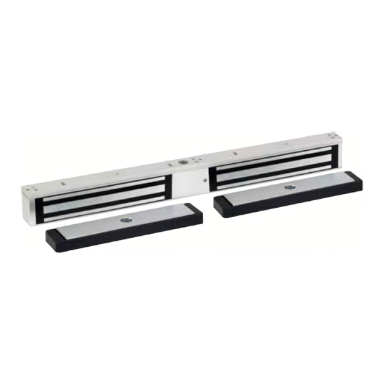
Quick Mount
Interlocking
Mounting Assembly
Magnet Lock
Electrical Instructions:
Use properly fused U. L. Listed Power Supply
Do not install a diode in parallel with any magnetic lock. A diode
will cause a delay when releasing the door and residual magnetism
to occur.
Access controls and/or release contacts must be located in series
with the positive (+) power lead of the EmLock.
Any low voltage condition will cause erratic operation of the
optional board sensor.
Although SDC recommends the use of a Regulated DC power supply,
a significant voltage drop will occur when using a full wave bridge rectifier.
Installation Location – Indoor Dry use only
PATENT NO. 5,376.910
P:\INST INSTRUCTIONS\EMLOCKS\INST-352
INSTALLATION INSTRUCTIONS
NARROW LINE EMLOCK
10"
Interlocking
Mounting Plate
Armature
REV -.5
10-22
352
25"
Frame
Electrical Specifications:
Dual Voltage:
Power Consumption:
DS Door Status Sensor: SPDT, 250mA@24VDC
LS Lock Status Sensor: SPDT,
Supplied Mounting Hardware
Page 1
Outswing
12 or 24VDC
1120mA@12VDC
618mA@24VDC
1A@24VDC
Resistive
Any suggestions or comments to this instruction or
product are welcome. Please contact us through
our website or email engineer@sdcsecurity.com
Advertisement
Table of Contents

Subscribe to Our Youtube Channel
Related Manuals for SDC 352


Summary of Contents for SDC 352
- Page 1 Any low voltage condition will cause erratic operation of the Supplied Mounting Hardware optional board sensor. Although SDC recommends the use of a Regulated DC power supply, a significant voltage drop will occur when using a full wave bridge rectifier. Installation Location – Indoor Dry use only PATENT NO.
- Page 2 Hardware used to install Interlocking Mounting Plates For wood frame install use supplied 1-1/4" wood screws. Use the supplied 1/2" screws to adjust the interlocking mounting plate. For metal frame install use supplied (M5 x 4mm) machine Screws P:\INST INSTRUCTIONS\EMLOCKS\INST-352 REV -.5 10-22 Page 2...
- Page 3 Do not touch the lock face with your hands. Clean lock face with Scotch-Brite pad by 3M (do not use sandpaper). Apply a thin film of rust inhibitor (LPS-3) on lock face. Repeat application on armature plate. P:\INST INSTRUCTIONS\EMLOCKS\INST-352 REV -.5 10-22 Page 3...
Need help?
Do you have a question about the 352 and is the answer not in the manual?
Questions and answers