Advertisement
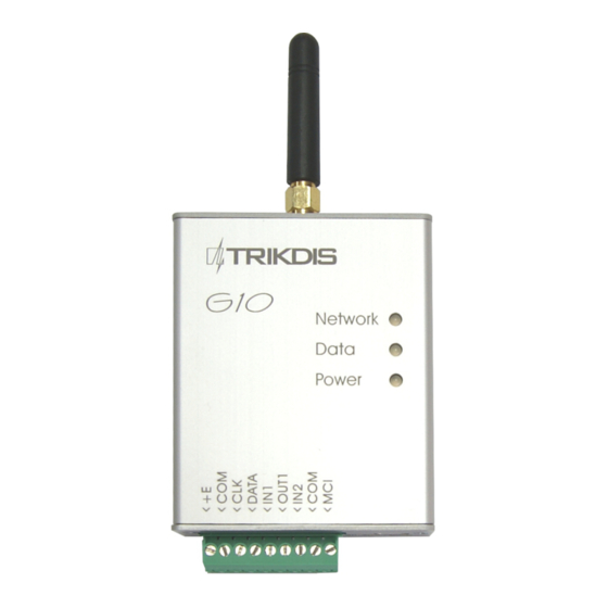
Note: The G10 communicator will be delivered with preset parameters to operate with PROTEGUS
1. Connect G10 communicator to security control panel
1.1. Disconnect the security control panel from power supply.
1.2. Using one of the wiring diagrams below connect the G10 communicator to control panel.
1.3. (Optional) if you want to remotely arm/disarm system:
1.3.1. Connect G10 output to the panel's keyswitch zone input (one wire, no resistors).
1.3.2. Program alarm panel`s zone as momentary keyswitch zone (see security control panel`s programming
manual).
1.4. Connect the security control panel to a power supply.
You can find more information on how to connect and program G10 series communicators here:
Note:
http://www.trikdis.com/en/products/alarm-transmitting-devices/gsm-gprs/gsm-communicator-g10
1.1.
Wiring diagrams
PYRONIX®
Wiring diagram to Pyronix
panels: MATRIX 424, MATRIX 832, MATRIX 832+,
MATRIX 6, MATRIX 816
Wiring diagram to DSC
PC1616, PC1832, PC1864 PC585, PC1565, PC5020.
www.PROTEGUS.eu
SETTING UP G10 COMMUNICATOR WITH PROTEGUS
®
Matrix Series control
DSC®
®
Power Series control panels:
GE® CADDX
®
Wiring diagram to GE
Caddx control panels: NX-8, NX-
8v2
PARADOX®
®
Wiring diagram to Paradox
SPECTRA SP5500, SP6000, SP7000, 1727, 1728, 1738;
MAGELLAN MG5000, MG5050;
DIGIPLEX EVO48, EVO192, EVO96, NE96, EVOHD;
ESPRIT E55, 728ULT, 738ULT.
security control panels:
Advertisement
Table of Contents

Subscribe to Our Youtube Channel
Summary of Contents for Trikdis G10
-
Page 1: Wiring Diagrams
1. Connect G10 communicator to security control panel 1.1. Disconnect the security control panel from power supply. 1.2. Using one of the wiring diagrams below connect the G10 communicator to control panel. 1.3. (Optional) if you want to remotely arm/disarm system: 1.3.1. - Page 2 The following settings have to be programmed for Caddx control panels: In order for communicator G10 to work with Caddx security control panels NX-4v2, NX-6v2, NX-8v2, NX-8e, control panels` locations 23 and 37 must be set as shown in the table below. When there are more than one partition in NX-8v2, NX-8e, also program locations 90, 93, 99, 102, 105, 108.


Need help?
Do you have a question about the G10 and is the answer not in the manual?
Questions and answers