Table of Contents
Advertisement
Quick Links
Download this manual
See also:
Installation Manual
Advertisement
Table of Contents

Subscribe to Our Youtube Channel
Related Manuals for Trikdis G16T


Summary of Contents for Trikdis G16T
- Page 1 GSM communicator G16T USER MANUAL UAB “TRIKDIS” Draugystės str. 17, LT-51229 Kaunas LITHUANIA E-mail: info@trikdis.lt Webpage: www.trikdis.lt...
-
Page 2: Table Of Contents
......................... 4 IGHT NDICATION OF OPERATION ............................5 ACKAGE CONTENTS ............................5 EFORE YOU BEGIN CONNECT G16T TO TRIKDISCONFIG ....................... 5 ........................... 6 TATUS BAR DESCRIPTION SET OPERATION PARAMETERS ........................7 ..........................7 YSTEM SETTINGS WINDOW → ARC ....................7... -
Page 3: Description
GSM communicator G16T 1 Description Communicator G16T is intended to upgrade any intruder alarm panel with telephone line communicator (TLC) for event signalling via cellular network. Communicator transmits full event information to Alarm Receiving Centre. Customers are informed about security system events in Protegus apps or with SMS messages. They can Arm/Disarm the alarm system remotely via panel’s keyswitch zone. -
Page 4: Communicator Board
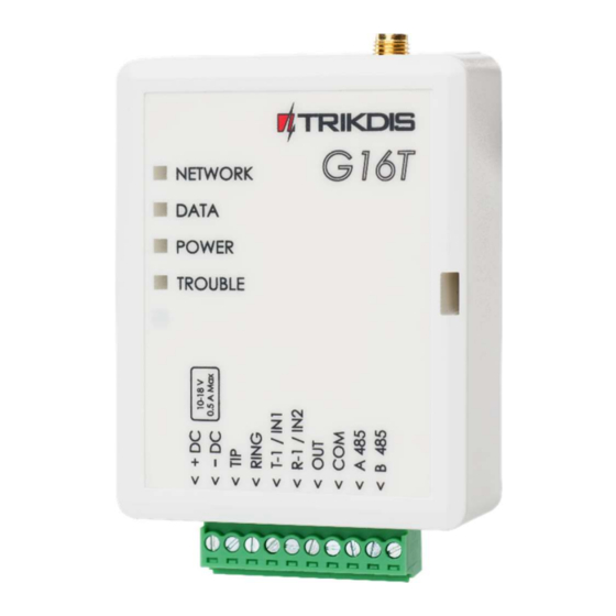
GSM communicator G16T Communicator board 1. GSM antenna SMA connector 5. USB Mini-B port for communicator programming 2. Light indicators 6. SIM card slot 3. Frontal case opening slot 4. Terminal for external connections Purpose of terminals Terminal Description 10 -18 VDC power supply... -
Page 5: Package Contents
SIM card. Order them separately from your local distributor. Connect G16T to TrikdisConfig Communicator can be configured using TrikdisConfig software for MS Window OS via USB cable or remotely. IMPORTANT: To use remote configuration function, Protegus service must be enabled. -
Page 6: Status Bar Description
Status bar Name Description IMEI/Unique ID IMEI number of the communicator Status Action status Device Communicator type (shows G16T or G16T_3G) Serial number Bootloader version Firmware version Hardware version State Connection status Admin Access level (shows up after access code is confirmed) ©1997-2017 Trikdis... -
Page 7: Set Operation Parameters
Write an appropriate Object number (4 symbols hexadecimal number). Use security panel account ID - Account ID is set in control panel, if enabled it will be transmitted to a G16T. Wait acknowledgement from ARC - after a successful reception of a message at the ARC, the communicator sends a kissoff signal to the control panel. -
Page 8: Arc Reporting Window→ Settings Tab
GSM communicator G16T First and Second channels (and Backup channels) First and second channels can work in parallel, by allowing the communicator to simultaneously transmit data via both channels. Select communication Mode and Protocol. If SMS reporting will be used – enter TRK encryption key and receivers phone number. -
Page 9: User Reporting Window → Sms & Call Reporting Tab
GSM communicator G16T User reporting window → SMS & Call Reporting tab Received event messages and internal communicator events can be reported to the users mobile phones via SMS messaging and calls. Each message come with an object name: enter the Object name of your choice to the text field. -
Page 10: Sim Card Window
GSM communicator G16T Command Data Description INFO Information about the communicator request. The response will include: communicator type, IMEI number, serial number and firmware version. RESET Restart the communicator. OUTPUTx Turn on the output, where “x” represents output number 1 or 2. -
Page 11: Physical Installation Process
GSM communicator G16T To write new parameters to the communicator, click Write [F5]. Note: To restore default settings of the communicator, press the Restore button under the Default settings in the bottom left corner of the configuration window. To create a configuration file which contains current parameters, click Save [F9]. - Page 12 GSM communicator G16T Connect GSM antenna. a) Remove the PCB board from the case bottom part; b) Then fix the bottom part to its place with screws and place the PCB board back into case Note: Sufficient GSM signal strength is level 5 (five yellow flashes of indicator Network).
-
Page 13: Add Communicator In Protegus
GSM communicator G16T 4.5.3 Input connection The communicator contains one input terminal (IN) for connection of sensors. For setting the input connection type see 3.1 General system settings. NO, Normally Open NC, Normally Closed Turn on the power supply. Add communicator in Protegus 1) Log in or sign in to www.protegus.eu. -
Page 14: Remote Control
GSM communicator G16T Remote control Communicator G16T can be controlled remotely using TrikdisConfig. To do so follow steps below: Open TrikdisConfig. At the field Remote access, in the field Unique ID enter the IMEI address. IMEI address is provided on the product package.
Need help?
Do you have a question about the G16T and is the answer not in the manual?
Questions and answers