
Subscribe to Our Youtube Channel
Related Manuals for Trikdis GET


Summary of Contents for Trikdis GET
- Page 1 Cellular/Ethernet communicator GET Installation manual October, 2023 www.trikdis.lt UAB Trikdis Draugystės g. 17, LT-51229 Kaunas, Lithuania +370 37 408 040 info@trikdis.lt...
-
Page 2: Table Of Contents
Communicator model types ..........................5 Specifications ................................ 5 Communicator elements ............................6 Purpose of terminals ............................. 6 LED indication of operation ........................... 6 Structural schematic of using the GET communicator ..................7 ....................8 UICK CONFIGURATION WITH RIKDIS ONFIG SOFTWARE Settings for connection with Protegus app ...................... - Page 3 Cellular/Ethernet communicator GET Safety requirements The communicator should be installed and maintained by qualified personnel. Prior to installation, please read this manual carefully in order to avoid mistakes that can lead to malfunction or even damage to the equipment. Disconnect the power supply before making any electrical connections.
-
Page 4: Description
Communicator works with Protegus application. With Protegus users can control their alarm system remotely and get notifications about security system events. The Protegus app works with all security alarm panels from various manufacturers to which the GET communicator is connected. Communicator can transmit event notifications to the Central Monitoring Station and work with Protegus simultaneously. -
Page 5: List Of Compatible Control Panels
Underlined - Control panels directly controlled by communicator. Firmware PARADOX control panels, which are directly controlled, must be V.4 or higher. * Connect control panels from other manufacturers to the GET communicator using the TIP RING terminals of the control panel. -
Page 6: Communicator Elements
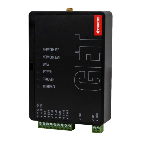
Cellular/Ethernet communicator GET Parameter Description Weight 110 g 1.4 Communicator elements 1. Cellular antenna SMA connector 2. Light indicators 3. Frontal case opening slot 4. Terminal for external connections 5. “RESET” button. 6. SIM2 card slot 7. SIM1 card slot 8. -
Page 7: Structural Schematic Of Using The Get Communicator
7 red blinks Lost connection with control panel (serial bus) INTERFACE Not used 1.7 Structural schematic of using the GET communicator Note: Before you begin, make sure that you have the necessary: 1. USB-C cable for configuration. 2. At least 4-wire cable for connecting communicator to control panel. -
Page 8: Quick Configuration With Trikdisconfig Software
Order the necessary components separately from your local distributor. Quick configuration with TrikdisConfig software 1. Download TrikdisConfig configuration software from www.trikdis.com (type “TrikdisConfig” in the search field) and install 2. Open the casing of the communicator with a flat-head screwdriver as shown below: 3. - Page 9 Cellular/Ethernet communicator GET Note: For the direct panel control to work, you will need to change the panel settings. How to do this is described in chapter 4.1 “Programming of control panels when the communicator is connected to the keypad bus or serial bus”.
-
Page 10: Settings For Connection With Central Monitoring Station
After finishing configuration, click the button Write [F5] and disconnect the USB cable. Note: For more information about other GET settings in TrikdisConfig, see chapter 6 „TrikdisConfig window description“. 2.2 Settings for connection with Central Monitoring Station In “System settings” window: 1. - Page 11 In “CMS reporting” window settings for “Primary channel”: 4. Communication type - select the IP connection method. 5. Protocol - select the protocol type for event messages: TRK (to TRIKDIS receivers), DC-09_2007 or DC-09_2012 (to universal receivers). 6. Encryption key - enter the encryption key that is set in the receiver.
-
Page 12: Installation And Wiring
IP address. After finishing configuration, click Write [F5] and disconnect the USB cable. Note: For more information about other GET settings in TrikdisConfig, see chapter 6 „TrikdisConfig window description“. Installation and wiring 3.1 Installation process 1. -
Page 13: Schematics For Wiring The Communicator To The Serial Or Keypad Bus Of The Control Panel
Cellular/Ethernet communicator GET 3.2 Schematics for wiring the communicator to the serial or keypad bus of the control panel Following one of the schematics provided below, connect communicator to the control panel. www.trikdis.com October, 2023... -
Page 14: Schematic For Wiring The Communicator To The Control Panel Keyswitch Zone
Note: GET communicator has 2 universal input / output terminals that can be set to the OUT (PGM) operating mode. The outputs (OUT) can control two areas of the security system. If you want to control the system in this way, in TrikdisConfig, in the "Panel settings"... -
Page 15: Schematics For Input Connection
Connect the input according to the selected input type (NO, NC, NC/EOL, NO/EOL, NO/DEOL, NC/DEOL), as shown in the schemes below: Note: If more inputs or outputs need to be connected to the communicator, connect the TRIKDIS iO-8 expander. 3.6 Schematics for wiring a relay With relay contacts you can control (turn on/off) various electric appliances. The I/O terminal of the communicator must be set to an output (OUT) mode. -
Page 16: Turn On The Communicator
4.1 Programming of control panels when the communicator is connected to the keypad bus or serial bus Below it is described how to program the security control panel so that the GET communicator could read events from the panel and control it remotely. -
Page 17: Programming Of Control Panels When The Communicator Is Connected To The Tip/Ring Terminals Of The Control Panel
3. Choose DTMF mode. 4. Select Contact ID communication protocol. 5. Enter the panel’s 4 digit account number. The control panel zone to which the GET output OUT is connected should be set to keyswitch zone for arming/disarming the control panel remotely. Note: Keyswitch zone can be momentary (pulse) or level. - Page 18 When all required settings are set, it is necessary to exit programming mode. Enter *99 in keypad. Special settings for Honeywell Vista 48 panel If you want to use GET communicator with Honeywell Vista 48 panel, set the following sections as described: Section...
-
Page 19: Remote Control
4. Power supply is connected (“POWER” LED illuminates green); 5. Registered to the network (“NETWORK LTE” LED illuminates green and blinks yellow). 3. Click “Add new system” and enter the GET’s “IMEI/Unique ID” number. This number can be found on the device and the packaging sticker. Click “Next”. -
Page 20: Additional Settings To Arm/Disarm The System Using The Control Panel's Keyswitch Zone
Important: The control panel zone to which the GET output OUT is connected to has to be set to keyswitch mode. Follow the instructions below if the security control panel will be controlled with communicator’s PGM output, turning on/off the control panel keyswitch zone. - Page 21 Cellular/Ethernet communicator GET 5. If there is another Area for the security system, then you need to click “Click to add an area”. Setting up the PGM output is similar to that described above. 6. After completing the settings, click the “Skip” button.
-
Page 22: Arming/Disarming The Alarm System With Protegus
2. Protegus will receive a message about a change in the status of the security system and the status icon will change its state. TrikdisConfig window description 6.1 TrikdisConfig status bar description After connecting the GET communicator and clicking Read [F4], TrikdisConfig will provide information about the connected device in the status bar: www.trikdis.com October, 2023... -
Page 23: System Settings" Window
Administrator Access level (shown after access code is approved) After pressing Read [F4], the program will read and show the settings which are set in the GET. Set the necessary settings according to the TrikdisConfig window descriptions given below. 6.2 “System settings” window “General”... -
Page 24: Panel Settings" Window
Cellular/Ethernet communicator GET “Panel settings” window “TLF” settings group The communicator is connected to the TIP RING terminals of the telephone communicator of the control panel. Security panel model – select the control panel model that will be connected to the communicator. - Page 25 Remote Arm/Disarm – when the checkbox is selected, the GET will directly control the control panel remotely. This setting will be visible only for directly controlled panels. For direct control of the control panels you need to change the panel settings, as described in section 4.1 “Programming of control panels when the communicator is connected to the...
-
Page 26: Cms Reporting" Window
Communication type - select the method of communication with the monitoring station receiver (IP). Protocol - select in which coding the events should be sent: TRK (to TRIKDIS receivers), DC-09_2007 or DC-09_2012 (to universal receivers). Encryption key - 6-digit message encryption key. The key written to the communicator must match the receiver’s key. -
Page 27: User Reporting" Window
“Backup” channel. Return from backup after - time after which the communicator GET will attempt to reconnect and transmit messages via the Primary channel. -
Page 28: Network Settings" Window
Cellular/Ethernet communicator GET “Protegus Cloud” settings group Enable connection – enable the Protegus service, the GET communicator will be able to exchange data with Protegus app and to be remotely configured via TrikdisConfig. Protegus Cloud access Code - 6-digit code for connecting to the Protegus app (default - 123456). - Page 29 Cellular/Ethernet communicator GET These settings must be made if the SIM card is inserted into the SIM1 slot of the communicator. “SIM card” settings group SIM card PIN - enter the SIM card PIN code. This code can be disabled by inserting the SIM card into a mobile phone and disabling the request.
-
Page 30: In/Out" Windows
Cellular/Ethernet communicator GET 6.7 “IN/OUT” windows The communicator has 2 universal (input / output) terminals. The table can set the terminal operating mode (Disabled, IN, OUT). The input must specify the type of circuit to be connected NC, NO, NO / EOL, NC / EOL, NO / DEOL, NC / DEOL. - Page 31 Cellular/Ethernet communicator GET “Module” tabs After adding the expander to the communicator as described above, in the “RS485 modules” window a new tab will appear with this module’s settings. The tab will be given a number. Bellow we describe the settings for iO-8 expanders.
-
Page 32: Event Summary" Window
POWER – message about low power supply voltage. REMOTE_FINISHED – message about disconnection from remote configuration with TrikdisConfig. REMOTE_STARTED – message about remote connection to configure GET with TrikdisConfig. TEST – periodic test message. Note: To enable periodic TEST messages and set their period, go to “CMS reporting” -> “Settings” -> “Test period”. -
Page 33: Test Communicator Performance
Cellular/Ethernet communicator GET 3. (Optional) in the “System name” field, enter the desired name for the communicator with this Unique ID. 4. Press “Configure”. 5. In the newly opened window click Read [F4]. If required, enter the administrator or installer code. To save the password, select “Remember password”. - Page 34 4. Press “Open firmware” and select the required firmware file. If you do not have the file, the newest firmware file can be downloaded by registered users from www.trikdis.com , under the download section of the GET communicator. 5. Press Update [F12].
-
Page 35: Annex
Cellular/Ethernet communicator GET 10 Annex The communicator converts Contact ID codes received from the alarm control panel into SIA codes. Contact ID to SIA code conversion table System Event CID Report Code SIA Report Code Medical alarm E100 "MA" Personal emergency E101 "QA"... - Page 36 Cellular/Ethernet communicator GET System Event CID Report Code SIA Report Code System reset in zone: <z> E305 "RR" Panel programming changed E306 "YG" System shutdown E308 "RR" Battery failure (309) E309 "YT" Ground fault E310 "US" Battery failure (311) E311 "YM"...
- Page 37 Cellular/Ethernet communicator GET System Event CID Report Code SIA Report Code User <v> disarmed remotely E407 "OP" Quick disarm E408 "OP" Remote disarm E409 "OS" Call back request made by CMS E411 "RB" Successful data download E412 "RS" Entry access denied for user <v>...
- Page 38 Cellular/Ethernet communicator GET System Event CID Report Code SIA Report Code Inaccurate Time/Date E626 "JT" System programming started E627 "LB" System programming finished E628 "LS" System event (631) E631 "JS" System event (632) E632 "JS" System not active (654) E654 "CD"...
- Page 39 Cellular/Ethernet communicator GET System Event CID Report Code SIA Report Code System reset restored in zone: <z> R305 "RR" No more battery failure (309) R309 "YR" Restore ground fault R310 "UR" No more battery failure (311) R311 "YR" Restore power supply overcurrent (312) R312 "YQ"...
- Page 40 Cellular/Ethernet communicator GET System Event CID Report Code SIA Report Code Recent disarm <v> user R459 “CR” Device enabled (501) R501 "RG" Device enabled (520) R520 "RC" Wireless sensor enabled in zone: <z> (552) R552 "YK" Zone <z> bypass cancelled R570 "UU"...
Need help?
Do you have a question about the GET and is the answer not in the manual?
Questions and answers