
Related Manuals for Trikdis G16


Summary of Contents for Trikdis G16
- Page 1 Cellular communicator G16 Installation manual October, 2018 www.trikdis.lt UAB Trikdis Draugystės str. 17, LT-51229 Kaunas, Lithuania +370 37 408 040 info@trikdis.lt...
-
Page 2: Table Of Contents
Cellular communicator G16 communica G16 Contents ................................4 ESCRIPTION ........................... 5 IST OF COMPATIBLE CONTROL PANELS ............................ 5 OMMUNICATOR MODEL TYPES ................................. 5 PECIFICATIONS ............................6 OMMUNICATOR ELEMENTS .............................. 6 URPOSE OF TERMINALS ........................... 6 INDICATION OF OPERATION ........................7... - Page 3 Cellular communicator G16 communica G16 Safety requirements The communicator should be installed and maintained by qualified personnel. Prior to installation, please read this manual carefully in order to avoid mistakes that can lead to malfunction or even damage to the equipment.
-
Page 4: Description
Communicator also works with Protegus application. With Protegus users can control their alarm system remotely and get notifications about security system events. Protegus app is compatible with all security alarm panels from various manufacturers that are supported by the G16 communicator. Communicator can transmit event notifications to the Central Monitoring Station and work with Protegus simultaneously. -
Page 5: List Of Compatible Control Panels
Honeywell Ademco Vista-20, Ademco Vista-48 *Connect control panels from other manufacturers to the G16T communicator. 1.2 Communicator model types This manual applies to these G16 models: G16_321x – 3 version, 1 SIM, 2G modem G16_331x – 3 version, 1 SIM, 3G modem ... -
Page 6: Communicator Elements
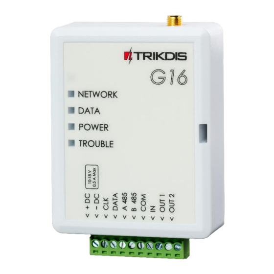
Cellular communicator G16 communica G16 1.4 Communicator elements 1. Cellular antenna SMA connector 2. Light indicators 3. Frontal case opening slot 4. Terminal for external connections 5. USB Mini-B port for communicator programming 6. SIM card slot 1.5 Purpose of terminals... -
Page 7: Structural Schematic With G16 Usage
Red blinking (Configuration mode) Memory fault Red solid (Configuration mode) Firmware is corrupted 1.7 Structural schematic with G16 usage Note: Before you begin, make sure that you have the necessary: 1) USB cable (Mini-B type) for configuration. 2) At least 4-wire cable for connecting communicator to control panel. -
Page 8: Quick Configuration With Trikdisconfig Software
(type “TrikdisConfig” in the search field) and install it. 2. Open the casing of the G16 with a flat-head screwdriver as shown below: 3. Using a USB Mini-B cable connect the G16 to the computer. 4. Run TrikdisConfig. The software will automatically recognize the connected communicator and will open a window for configuration. -
Page 9: Settings For Connection With Alarm Receiving Center
After finishing configuration, click the button Write [F5] and disconnect the USB cable. Note: For more information about other G16 settings in TrikdisConfig, see chapter 6 “TrikdisConfig window description”. 2.2 Settings for connection with Alarm Receiving Center In “System settings” window: 1) Enter Object ID (account) number provided by the Central Monitoring Station (4 characters, 0-9, A-F). - Page 10 In “ARC reporting” window settings for “Primary channel”: 3) Communication type - select the IP connection method (We do not recommend SMS as the primary channel). 4) Protocol - select the protocol type for event messages: TRK (to TRIKDIS receivers), DC-09_2007 or DC-09_2012 (to universal receivers).
-
Page 11: Installation And Wiring
12) Change the APN name. APN can be found on the website of the SIM card operator (“internet” is universal and works in many operator networks). After finishing configuration, click Write [F5] and disconnect the USB cable. Note: For more information about other G16 settings in TrikdisConfig, see chapter 6 “TrikdisConfig window description”. Installation and wiring 3.1 Physical installation process 1) Remove the top cover and pull out the contact terminal. -
Page 12: Schematics For Wiring The Communicator To A Security Control Panel
Cellular communicator G16 communica G16 3.2 Schematics for wiring the communicator to a security control panel Following one of the schematics provided below, connect communicator to the control panel. 1. Schemes for connecting to the security control panels: www.trikdis.com October, 2018... -
Page 13: Schematic For Connecting To Panel Keyswitch Zone
Cellular communicator G16 communica G16 3.3 Schematic for connecting to panel keyswitch zone Follow this schematic if the control panel will be armed/disarmed with a G16 PGM output turning on/off the panel’s keyswitch zone. Note: G16 communicator has two programmable outputs OUT (PGM) that can control two areas of the security system. -
Page 14: Schematics For Wiring A Relay
If more inputs or outputs need to be connected to the communicator, or if you want to connect a temperature sensor, connect the TRIKDIS iO series wired or wireless output expander. 3.7 Turn on the communicator To start the communicator, turn on the security control panel’s power supply. This LED indication on the G16 communicator must show: ... -
Page 15: Programming The Control Panel
G16 Programming the control panel Below it is described how to program the security control panel so that the G16 communicator could read events from the panel and control it remotely. To enable remote control of the security panel, make sure that the checkbox Remote Arm/Disarm is selected in the TrikdisConfig window “System settings”. -
Page 16: Remote Control
Open Configuration > General > Alarm Reporting. In the 3rd Party Device Configuration settings group you need to enter: 1. Enable 3rd Party Device Reporting - select this checkbox. 2. 3rd Party Device Type - set “Trikdis”. 3. Serial port - set “Serial Port 1 (Plugged In, In Use By 3rd Party Device)”. - Page 17 3. Power supply is connected (“POWER” LED illuminates green); 4. Registered to the network (“NETWORK” LED illuminates green and blinks yellow). 3) Click Add new system and enter the G16’s “IMEI/Unique ID” number. This number can be found on the device and the packaging sticker. Click Next.
-
Page 18: Dditional Settings To Arm Disarm The System Using The Control Panels Keyswitch Zone
The control panel zone to which the G16 output OUT is connected to has to be set to keyswitch mode. Follow the instructions below if the security control panel will be controlled with a G16 PGM output, turning on/off the control panel keyswitch zone. -
Page 19: Configuration And Control With Sms Messages
Set APN user. E.g.: 123456 CONNECT USER=User PASS=password Set APN password. E.g.: 123456 CONNECT PASS=Password Select security control panel from a list. E.g. (assign control panel Paradox SP6000 that is number 4 on the list to the G16): 123456 CONNECT CP=4 www.trikdis.com October, 2018... -
Page 20: Trikdisconfig Window Description
Administrator Access level (shown after access code is approved) After pressing Read [F4], the program will read and show the settings which are set in the G16. Set the necessary settings according to the TrikdisConfig window descriptions given below. www.trikdis.com... -
Page 21: System Settings" Window
Remote Arm/Disarm - when the checkbox is selected, the G16 will directly control the control panel remotely. This setting will be visible only for directly controlled panels. For direct control of the control panels you need to change the panel settings, as described in section 4 “Programming the control panel”. -
Page 22: Arc Reporting" Window
Communication type - select which method for connecting to the monitoring station receiver will be used: IP or SMS. Protocol - select in which coding the events should be sent: TRK (to TRIKDIS receivers), DC-09_2007 or DC-09_2012 (to universal receivers). - Page 23 Backup channel. Return from backup after - time after which the G16 will attempt to reconnect and transmit messages via the Primary channel.
-
Page 24: User Reporting" Window
“Protegus Cloud” settings group Enable connection – enable the Protegus service, the G16 will be able to exchange data with Protegus app and to be remotely configured via TrikdisConfig. Cloud access Code - 6-digit code for connecting to the Protegus app (default - 123456). -
Page 25: Sim Card" Window
Cellular communicator G16 communica G16 SMS language - choose the language for SMS messages (SMS messages can be sent with language-specific characters). Tel numbers for SMS/Call reporting - enter up to 4 user phone numbers that will receive event SMS messages or calls. -
Page 26: Rs485 Modules" Window
Cellular communicator G16 communica G16 APN - enter APN (Access Point Name). It is required for connecting the communicator to the internet. APN can be found on the website of the SIM card operator (“internet” is universal and works in the networks of many operators). - Page 27 Cellular communicator G16 communica G16 Expander iO-8 has 8 universal (input/output) terminal contacts. Input Count – select what number of terminal contacts should be set to input (IN) mode. The rest of the terminal contacts will become outputs (OUT).
-
Page 28: Event Summary" Window
In this window, you can turn on, turn off or change the internal event messages sent by the device. After turning off the internal event in this window, it will not be sent irrespective of other settings. COMMUNICATION – message about connection error between the control panel and G16. IN_ALARM – message about input (IN) circuit trigger. -
Page 29: Remote Configuration
This number can be found on the device and the packaging sticker. 3. (Optional) in the System name field, enter the desired name for the G16 with this Unique ID. 4. Press Configure. 5. In the newly opened window click Read [F4]. - Page 30 4. Press Open firmware and select the required firmware file. If you do not have the file, the newest firmware file can be downloaded by registered users from www.trikdis.com , under the download section of the G16 communicator. 5. Press Update [F12]. 6. Wait for the update to complete.
Need help?
Do you have a question about the G16 and is the answer not in the manual?
Questions and answers