
Subscribe to Our Youtube Channel
Related Manuals for Trikdis E14


Summary of Contents for Trikdis E14
- Page 1 Ethernet communicator E14 USER MANUAL July, 2018 www.trikdis.lt UAB Trikdis Draugystės g. 17, LT-51229 Kaunas, Lietuva +370 37 408 040 info@trikdis.lt...
-
Page 2: Table Of Contents
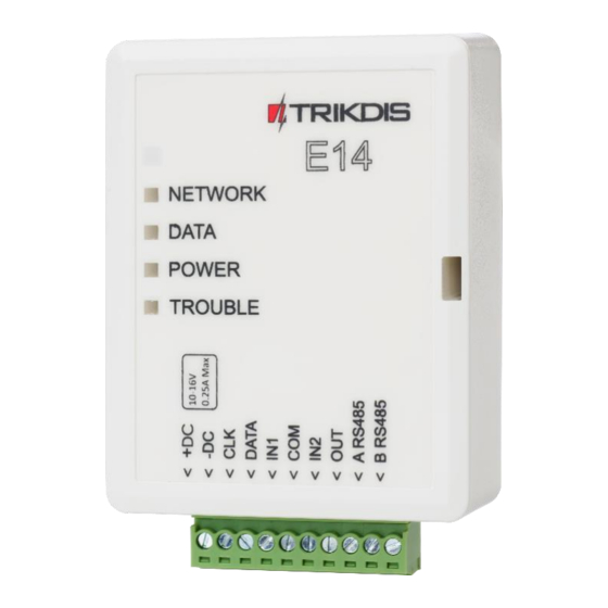
Terminal block description ............................5 Light indication................................5 System overview ................................. 6 Package Contents ................................ 6 CONNECT E14 TO TRIKDISCONFIG ..........................6 Add communicator in Protegus ..................Error! Bookmark not defined. Communication settings with ARC ..........................8 PHYSICAL INSTALLATION............................... 9 Wire communicator to panel ............................ -
Page 3: Safety Requirements
Ethernet communicator E14 Safety Requirements The security alarm system should be installed and maintained by qualified personnel. Prior to installation, please read carefully this manual in order to avoid mistakes that can lead to malfunction or even damage to the equipment. -
Page 4: Description
Ethernet communicator E14 1 Description Communicator E14 is intended to upgrade compatible intruder alarm panels for event signalling via wired Internet (Ethernet). Customers are informed about security system events in Protegus app. Communicator can Arm/Disarm the alarm system via keyswitch zone. -
Page 5: Technical Parameters
Ethernet communicator E14 1.2 Technical Parameters Parameter Description Power supply voltage 10-16 V DC Current consumption 120 mA (stand-by) Up to 250 mA (transmitting) Ethernet connection IEEE802.3, 10 Base-T, RJ45 socket Data pack content Contact ID format codes Memory Up to 100 messages Inputs 2, NC/NO/EOL-2,2 kΩ... -
Page 6: System Overview
1.6 Package Contents Communicator E14 1 pc. 2. Connect E14 to TrikdisConfig 1. Download TrikdisConfig from www.trikdis.com (in search field type TrikdisConfig), and install it. 2. Remove the E14 cover by using a flat screwdriver as shown below: www.trikdis.com July, 2018... - Page 7 Ethernet communicator E14 3. Connect E14 to your computer via USB Mini-B cable. 4. Run the configuration software TrikdisConfig. The software will automatically recognise E14 and will open a window for communicator configuration. Click Read [F4] to read the communicators parameters and enter the Administrator or Installer code in the pop-up window.
-
Page 8: Communication Settings With Arc
3) Change the Service code for logging in to Protegus, if you want to ask users to add it by adding the Protegus system in the application (factory default - 123456). More about other TrikdisConfig E14 settings see 6 " Set operation parameters ". 2.2 Communication settings with ARC In the “System Settings”... -
Page 9: Physical Installation
8) Encryption key – enter encryption key that is set in the receiver. 9) (Recommended) Configure the Backup Channel Settings. 10) TCP protocol – select which encoding protocol will be use: TRK (for TRIKDIS receivers), DC-09_2007 or DC-09_2012 (for universal receivers). -
Page 10: For Utc Interlogix (Caddx) Control Panels Program The Following Settings
For UTC Interlogix (Caddx) control panels program the following settings In order for communicator E14 to work with Caddx security control panels NX-4v2, NX-6v2, NX-8v2, NX-8e, control panels` locations 23 and/or 37 must be set as shown in the table below. When there are more than one partition in NX-8v2, NX-8e, also program locations 90, 93, 99, 102, 105, 108. -
Page 11: Optional) Input Connection
Ethernet communicator E14 If you want to select all eight features of a segment, press 1, 2, 3, 4, 5, 6, 7, 8. Symbol * shows that feature is turned off. Location Segment Features of segment 12345678 12345678 37 (optional, system events) -
Page 12: Add Communicator In Protegus
4.1 Additional settings for ARM/DISARM the system via keyswitch zone. IMPORTANT: Control panels area, to which E14 output OUT is connected, must be set as keyswitch zone. Follow the instructions below if the control panel is not directly managed, but with a E14 PGM output switching keyswitch zone. www.trikdis.com... - Page 13 Ethernet communicator E14 1. After entering the IMEI/Unique ID number, click Next. In the new window, click on the Areas in the side menu. In the window that appears, specify how many areas (1 or 2) are in the system and press Next.
-
Page 14: System Management With Protegus
3. On request enter the user code or Protegus password. 5. Connect E14 to TrikdisConfig Communicator can be configured using TrikdisConfig software for MS Windows via USB cable or remotely. Important: To use remote configuration function, Protegus service must be enabled. - Page 15 Ethernet communicator E14 a. Using USB cable: run the configuration software TrikdisConfig. The software will automatically recognise the connected device and will open a window for communicator configuration; or Remotely: run the configuration software TrikdisConfig. In section Remote access, field Unique ID enter MAC address of communicator (MAC address is provided on the product package).
-
Page 16: Set Operation Parameters
Ethernet communicator E14 Set the required parameters for E14 and click Write [F5]. To disconnect from E14, click Disconnect and exit from TrikdisConfig. Note: If administrator code is set as default (123456), it is not required to enter it and the request window will not appear. -
Page 17: System Settings Window
Ethernet communicator E14 6.2 System settings window General • Enter system Account number (4 symbols hexadecimal number) or select Use security panel account ID checkbox. • Test period: periodic test messages will be sent according to a time interval set in this section. -
Page 18: Reporting Window → Arc Reporting Tab
Ethernet communicator E14 o Pulse: a status will take time as indicated in Pulse Time (pulse period in seconds) field. o Level: a status will change and remain the same until the next command. 6.3 Reporting window → ARC reporting tab Primary and Backup settings •... -
Page 19: Event Summary Window
Ethernet communicator E14 • Enable the Protegus cloud service at Reporting → PROTEGUS service tab. • For additional security enter Service code (default is 123456). If the Service code is changed, you will need to enter it, when adding the communicator to Protegus. -
Page 20: Reset Factory Settings
Ethernet communicator E14 6.6 Reset factory settings To restore the communicator’s factory defaults, you need to click the Restore button in the TrikgisConfig window. 7. Perform system test 1. After configuration and installation is complete, perform a system test. Activate an event in the control panel, and make sure that the event arrives to the alarm receiving centre or is received by the mobile application. - Page 21 If you do not have the file, the newest firmware file can be downloaded by registered user from www.trikdis.com, under the download section of the E14 communicator. 5. To save configuration parameters, which were set earlier, check box Preserve settings.
Need help?
Do you have a question about the E14 and is the answer not in the manual?
Questions and answers