
Subscribe to Our Youtube Channel
Related Manuals for Trikdis G17F


Summary of Contents for Trikdis G17F
- Page 1 GSM communicator for fire alarm control panels G17F Installation manual February, 2019 www.trikdis.com UAB Trikdis Draugystės str. 17, LT-51229 Kaunas, Lithuania +370 37 408040 info@trikdis.lt...
-
Page 2: Table Of Contents
GSM communicator for fire control panels G17F Contents CONTENTS ............................2 SAFETY PRECAUTIONS ........................3 DESCRIPTION ..........................4 ........................... 5 PECIFICATIONS G17F ....................6 LEMENTS OF THE COMMUNICATOR ........................6 URPOSE OF TERMINALS ......................6 INDICATION OF OPERATION .................... 7 OMPONENTS NECESSARY FOR INSTALLATION QUICK CONFIGURATION USING TRIKDISCONFIG SOFTWARE ............ -
Page 3: Safety Precautions
GSM communicator for fire control panels G17F Safety precautions The communicator should be installed and maintained only by qualified personnel. Please read this manual carefully prior to installation in order to avoid mistakes that can lead to malfunction or even damage to the equipment. -
Page 4: Description
The G17F is used for transmitting fire alarm control panel messages via cellular network. Principle of operation. When an input (zone) of the communicator is violated, the G17F will transmit an event message to the Central Monitoring Station’s receiver or to the Protegus app using mobile internet. -
Page 5: Specifications
GSM communicator for fire control panels G17F 1.1 Specifications Parameter Description GSM/GPRS modem frequencies 850 / 900 / 1800 / 1900 MHz 3G modem frequencies 800 / 850 / 900 / 1900 / 2100 MHz LTE modem frequencies 700 / 800 / 900 / 1800 / 2100 / 2600 MHz... -
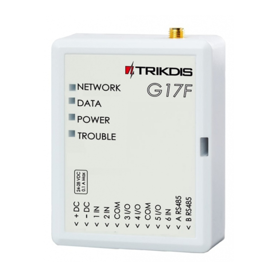
Page 6: Elements Of The G17F Communicator
GSM communicator for fire control panels G17F 1.2 Elements of the G17F communicator 1. SMA connector for GSM antenna. 2. Indicator lights. 3. Slot for removing top cover. 4. Terminals for connecting wires. 5. USB Mini-B connector for programming the communicator. -
Page 7: Components Necessary For Installation
Order the necessary components separately from your local distributor. Quick configuration using TrikdisConfig software 1) Download the configuration software TrikdisConfig from www.trikdis.com (type “TrikdisConfig” in the search field) and install it. 2) Remove the lid of the G17F using a flat-head screwdriver as shown below: www.trikdis.com February, 2019... -
Page 8: Settings For Connecting To Protegus App
4) Launch TrikdisConfig. The program will automatically recognize the connected device and will automatically open the G17F configuration window. 5) Click the Read [F4] button to see the current parameters of the G17F. If a window requesting the administrator or installer code opens, enter the 6-digit code. - Page 9 GSM communicator for fire control panels G17F In the “System options” window, “SIM” settings group: 3) Enter the SIM card PIN code. 4) Change the APN. You will find the APN on the SIM operator’s website. “Internet” is universal and works in the networks of most operators.
-
Page 10: Settings For Connecting To Central Monitoring Station
After finishing configuration, click the Write [F5] button and disconnect the USB cable. Note: See chapter 5 “Description of TrikdisConfig windows” to find more about other G17F settings in TrikdisConfig. 2.2 Settings for connecting to Central Monitoring Station In the “System Options”... - Page 11 10) (Recommended) Enter the Backup channel 2 phone number. After finishing configuration, click the Write [F5] button and disconnect the USB cable. Note: See chapter 5 “Description of TrikdisConfig windows” to find more about other G17F settings in TrikdisConfig. www.trikdis.com...
-
Page 12: Wiring Schematics, Installation And Turning On The System
If you want to avoid entering the PIN code in TrikdisConfig, insert the SIM card into a phone and disable the PIN code request function. 8. To configure the G17F remotely, insert a SIM card with disabled PIN code requests. Turn on the communicator’s power supply. If the G17F was not configured using TrikdisConfig and Protegus... -
Page 13: Schematic For Connecting The Communicator To A Fire Control Panel
3.2 Schematic for connecting the communicator to a fire control panel 3.3 Schematic for connecting the communicator to an INIM Smartline fire control panel Slave mode must be set for the INIM Smartline panel when it is connected to the G17F communicator via RS485 bus. -
Page 14: Trikdisconfig Settings When An Inim Smartline Fire Control Panel Is Connected
1) Choose the Inim Smartline module. In the “PGM” window: 2) Specify the G17F communicator’s PGM output that is connected to the fire control panel’s 19 (+Dialer) terminal. Set Output definition – Inim communicator. (The PGM output is turned on when the G17F communicator has problems connecting to the CMS or is unable to send messages. - Page 15 GSM communicator for fire control panels G17F In the “Users & Reporting” window: 3) Enter phone numbers of users who should get messages from the G17F communicator. In the “SMS for Control panel” tab 4) Users will get SMS messages and phone calls about events that are ticked. You can add additional CID event codes in the CID column.
-
Page 16: Schematics For Connecting Inputs
TrikdisConfig window Zones. Schematics of NO, NC, EOL type circuits: 3.6 Schematic for connecting iO series expander modules If the communicator needs more inputs IN or outputs OUT, connect a wired or wireless TRIKDIS iO series input and output expander. www.trikdis.com... -
Page 17: Schematic For Connecting An Io-8 Expander Module
GSM antenna. If the indication is different, search for the explanation in chapter 1.4 “LED indication of operation”. If the G17F’s indicator lights are completely inactive, check the power supply and connections. Remote control 4.1 Adding the communicator to Protegus app Using Protegus, users can see the system’s state and receive notifications about system events. -
Page 18: Configuration And Control Via Sms Messages
GSM communicator for fire control panels G17F 3) Click Add new system and enter the G17F’s “Unique ID” number. It can be found on the device and packaging sticker. After entering the unique ID, click the Next button. 4.2 Configuration and control via SMS messages 1. - Page 19 GSM communicator for fire control panels G17F Command Data Description PULSE=ttt Turn on an output for a few seconds - “x” is the OUT output number, and “ttt” is a three-digit number that specifies pulse time in seconds. E.g.: OUTPUT1 123456 PULSE=002 New password Change password.
-
Page 20: Control Pgm Outputs Using Phone Calls
The user must be allowed to control outputs OUT and the output OUT must have type “Remote control” assigned (using TrikdisConfig). Call the number of the G17F’s SIM card. The G17F will answer the call and you can dial commands using the phone’s keypad (see the table). -
Page 21: Description Of Trikdisconfig Windows
Role Access level (shown after access code is approved) When the Read [F4] button is clicked, the program will read and show settings currently saved on the G17F. With TrikdisConfig, set the required parameters using the following program window descriptions. -
Page 22: System Options" Window
GSM communicator for fire control panels G17F 5.2 “System Options” window “System general” tab “General” settings group Object ID – if events are going to be sent to the CMS, enter the Object ID (4-symbol hexadecimal number, 0-9, A-F) given by the CMS. - Page 23 GSM communicator for fire control panels G17F “Access” tab Settings group “Access codes” Administrator Code – gives full access to configuration functions (default code – 123456). SMS password – password for remote control and programming via SMS messages (default code –...
-
Page 24: Reporting To Cms" Window
IP receivers capable of receiving event messages sent in SIA DC-09 protocols. Phone number – (only for SMS messages) enter the phone number of a TRIKDIS SMS receiver. The phone number must start with the country code (e.g.: 370xxxxxxxx). - Page 25 Configure the backup channel using the same settings as described above. Settings group “Settings” Return to Primary after – time period after which the G17F will attempt to regain connection with the Primary channel. IP PING period – sending period of internal PING signals for checking connectivity. These messages are sent only via IP channel.
-
Page 26: Users & Reporting" Window
PGM – if the box is ticked, the user can remotely control outputs. ACK – if the box is ticked, the G17F will send SMS messages with SMS answer text to the user after every received SMS command. - Page 27 GSM communicator for fire control panels G17F “SMS answer texts” tab Settings group “SMS answer texts” Edit the answer texts to control commands sent via SMS messages in the column SMS text. “SMS for Control panel” tab Zn – event’s number on the list.
-
Page 28: Modules" Window
Serial No. – mandatory 6-digit number that can be found on the module’s casing and its packaging. Name – you can give the module a name. Firmware version – the firmware version will be shown when the G17F finds the connected module. 5.6 “Zones” window “Zones settings”... -
Page 29: Pgm" Window
“Outputs” tab PGM No – PGM output’s number on the list. PGM output – assign outputs OUT of the G17F or of an external device to a PGM. Output definition – select operational mode of an output OUT. -
Page 30: System Events" Window
GSM communicator for fire control panels G17F “SMS & Call reporting” tab PGM – the number of output OUT and turn on/off event type (“Event” – output OUT turn on event and “Restore” – OUT turn off event). SMS text – output OUT turn on/off event name that will be included in the event’s SMS message. -
Page 31: Events Log" Window
Clear Log button – for clearing the event log entries from the device’s memory. In the table, you can find the Event No., Time, CID code, Event definition. The events log can show up to 1000 events stored in the G17F’s memory. 5.10 Restore default settings To restore the communicator’s default settings, click the TrikdisConfig button Restore. -
Page 32: Setting Parameters Remotely
GSM communicator for fire control panels G17F 6 Setting parameters remotely IMPORTANT: Remote configuration will only work when the G17F: 1. Has an inserted and activated SIM card with the PIN code entered or disabled. 2. Has Protegus service enabled. See 5.4 “Users & Reporting” window. - Page 33 GSM communicator for fire control panels G17F 2. Connect the communicator to the computer using a USB Mini-B cable or connect to the communicator remotely. If a newer version of firmware is available, the program will automatically offer to install it.
Need help?
Do you have a question about the G17F and is the answer not in the manual?
Questions and answers