
Related Manuals for SimpliVity OmniStack

Summary of Contents for SimpliVity OmniStack
- Page 1 SimpliVity OmniStack Integrated Solution with Cisco UCS C240 M4SX Hardware Installation and Maintenance Guide www.SimpliVity.com...
- Page 2 Customer support To contact SimpliVity Customer Support, visit https://support.simplivity.com. When contacting a representative, you need to know the serial number of your OmniStack server to verify your service subscription. SimpliVity uses OmniWatch to automatically monitor the health of your OmniStack equipment and have it send us notifications of any alerts or errors.
- Page 3 Intended audience This document is intended for users of SimpliVity OmniStack products who want to install, manage, and monitor their hyperconverged IT infrastructure. This information is intended for system administrators experienced in hypervisor technology, virtual machine management, and data center operations.
- Page 4 SimpliVity documentation conventions SimpliVity documentation uses the following conventions to assist your reading. General formatting Monospace font represents a command line syntax, file path, system output, or similar code. Italic font represents a user-defined name or variable. Bold font represents a user interface element, such as a button or tab, with which a user interacts.
- Page 5 SimpliVity documentation feedback We welcome your feedback, suggestions, and comments to help us continue to improve the quality of our documentation. Send your comments to Documentation-Feedback@SimpliVity.com and include as much detail as possible to help us identify the affected area.
-
Page 6: Table Of Contents
Contents Chapter 1: Hardware overview....................8 Hardware components........................8 About the front panel components....................13 About the back panel components..................... 15 Environmental and technical specifications..................17 Enclosure size and weight......................17 Power and thermal........................18 Temperature and humidity......................18 Altitude............................19 Vibration and shock........................19 Agency compliance........................ - Page 7 Remove a power supply........................53 Install a power supply........................54 Chapter 7: About network cabling options................55 About the 10GbE-only configuration....................55 About the Switch-Connected configuration..................56 About the Direct-Connect Mode Cluster configuration..............58 About the SingleConnect Cluster configuration................59 Appendix A: SimpliVity terminology..................62 Contents...
-
Page 8: Chapter 1: Hardware Overview
Hardware components Each OmniStack server provides computing, storage, and network resources to the virtual machines (VMs) in the Federation. When you need more capacity or performance, you can add more OmniStack servers to a Federation, with no disruption to users. - Page 9 Component Remote Site Small Medium and Large Capacity 400GB 400GB 400GB Interface Dimension 2.5" 2.5" 2.5" RAID type RAID1 RAID1 RAID5 Front HDD drives Quantity Capacity 1.0TB 1.0TB (V3) Medium model: 1.0TB 1.2TB (V4) Large model: 1.2TB Interface 7.2K 7.2K (V3) Medium model: 7.2K 10K (V4)
- Page 10 ■ 192GB;4x32GB + 4x16GB RDIMM @ 2133MHz or 2400MHz ■ 256GB;8x32GB RDIMM @ 2133MHz or 2400MHz ■ 384GB;12x32GB RDIMM @ 1866MHz or 2133MHz Contact your SimpliVity sales representative to learn about memory sizes greater than 384GB. ■ 256GB;8x32GB RDIMM @ Dual CPU 2133MHz or 2400MHz ■...
- Page 11 Component Remote Site Small Medium and Large Remote server Web-based UCSM or CIMC (IPMI) processor and network port. management management. Table 2: Hardware components by All Flash model (All Flash models contain SSD physical drives only) Component Small, Medium, Large All Flash Model Intel Xeon E5-2600 V4 series CPU Count...
- Page 12 ■ 192GB;4x32GB + 4x16GB RDIMM @ 2133MHz or 2400MHz Frequency ■ 256GB;8x32GB RDIMM @ 2133MHz or 2400MHz ■ 384GB;12x32GB RDIMM @ 1866MHz or 2133MHz Contact your SimpliVity sales representative to learn about memory sizes greater than 384GB. ■ 256GB;8x32GB RDIMM @ 2133MHz or 2400MHz Dual CPU ■...
-
Page 13: About The Front Panel Components
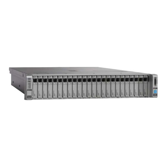
About the front panel components The following figure and associated table describe the front panel of a UCS C240 M4SX server. Figure 1: UCS C240 M4SX front panel Table 3: UCS C240 M4SX front panel component descriptions Callout Component Description Console connector Enables you to attach a custom cable that provides keyboard, video, and... - Page 14 Callout Component Description Storage 24 drives, size 2.5", with activity (right) and fault (left) LED indicators. An embossed number on the enclosure shows the drive numbering from 1 to 24, left to right. ■ The Remote Site model contain 6 disks: Disks 1 and 2 are SSDs. Disks 3 to 6 are HDDs.
-
Page 15: About The Back Panel Components
Callout Component Description Power button Controls power to the server and indicates whether there is power to the enclosure. If the indicator is green, the enclosure is receiving power. About the back panel components The following image and table describe the back panel of a UCS C240 M4SX server. Figure 2: Back panel components Table 4: Back panel component descriptions Callout... - Page 16 SimpliVity Storage and Federation networks. Note: If you are managing the server in Integrated Mode using UCSM, use 10GbE ports for all three SimpliVity networks: Storage, Federation, and Management. USB 3.0 ports (two) Provides keyboard, video, and mouse (KVM) connection through USB for accessing the server console.
-
Page 17: Environmental And Technical Specifications
Callout Component Description Serial port Serial RJ-45 connector. 1GbE network interfaces There are two embedded 1GbE network interfaces numbered 1 and 2, from left to right. They are logically named LAN1 and LAN2. VGA video port (DB-15 connector) VGA port that provides KVM connector for accessing the server console. -
Page 18: Power And Thermal
Power and thermal A UCS C240 M4SX server configured for deployment in a SimpliVity Federation meets the power and thermal specification for a fully-configured enclosure with two power supply units (PSU) described in the Cisco product documentation. Specification Description AC input voltage Nominal range: 100–120VAC, 200–240VAC... -
Page 19: Altitude
Altitude (storage) 0 to 40,000 ft Vibration and shock A UCS C240 M4SX server configured for deployment in a SimpliVity Federation does not exceed the vibration and shock limit specifications for a fully-configured enclosure. Agency compliance A UCS C240 M4SX server, when configured for deployment in a SimpliVity Federation, meets the same compliance standards as a standard Cisco UCS C240 M4SX server. -
Page 20: Chapter 2: Install The Server Hardware
Chapter 2: Install the server hardware This section contains the following topics: • About electrostatic discharge • Shipping carton contents • Hardware not supplied in the shipping carton • Install the server in a rack • Connect the power cables Connect the network cables •... -
Page 21: Hardware Not Supplied In The Shipping Carton
Part Description ■ Two standard power cords. Power cords (locale specific) ■ Two rack power distribution unit (PDU) cords. 1 SFP+ Direct Attach (Twinax) cable Connects a 10GbE interface on one server directly to a 10GbE interface on another server. Depending on your network configuration and the distance between the server, you might need different or additional cables. -
Page 22: Rack Requirements
Hardware Description Application 10GbE data cables 2SFP+ Direct Attach active Connects the 10GbE interfaces cables. on one server to a 10GbE switch. Redundant network switches Required number of switches. Connects devices to a network. The number of switches depends on your network configuration. Redundant Uninterruptible Required number of UPS Provides temporary power to the... -
Page 23: Install The Server In A Rack
Install the server in a rack Before you begin ■ You have read the safety instructions in the Product Information Guide supplied with your server. ■ For first time installers, you have read the Rack Installation Instructions included in the rail kit. The rail kit instructions also explain stabilizing the rack, installing devices, and power distribution. -
Page 24: Connect The Power Cables
Connect the network cables Procedure overview You use the dual-port 10GbE mLOM ports for the SimpliVity Storage, Federation, and Management networks, which is the preferred method if you are using UCS Manager (UCSM). You can use the embedded dual-port 1GbE network interface card (NIC) for the Management network, which is optional if you are using UCSM. -
Page 25: Power On The Server
Procedure 1. Obtain the network cables needed for the network configuration. 2. Connect the cables for the three SimpliVity networks only according to the guidelines in the "About network cabling options" section. 3. Ensure that no other network interfaces, such as optional 10GbE interfaces, are connected to your network before deploying the server to a Federation. - Page 26 Procedure 1. Go to the front of the server. 2. Press the power button. 3. Ensure the health indicators on the front panel indicate normal operation for all components. Note: If an error occurs when starting a server, contact Customer Support.
-
Page 27: Chapter 3: About Ucs Server Management
Note: The SimpliVity OmniStack with Cisco UCS Manager Integration document does not provide all required information. You can use the document for some settings, but the table below is more complete. Tasks Steps... - Page 28 Details Connect the 10GbE mLOM ports for See "About network cabling options." the three SimpliVity networks to the FI in Fabric A and the FI in Fabric B. Power-on the server and wait for You press the power button on the UCSM to discover it.
- Page 29 Tasks Steps Details 1. Select Equipment tab > (Optional) Create uplink ports for each Fabric Interconnects > Fabric FI in Fabric A and Fabric B to handle Interconnect A > Physical Ports the traffic between the FIs and the next tab >...
- Page 30 Tasks Steps Details (Optional) Create a vNIC Placement In the "Create vNIC Placement Policy" dialog, set the Selection Preference Policy. for virtual slot 1 and slot 2 to Assigned Only. Create a LAN Connectivity Policy. In the "Create LAN Connectivity Policy" wizard, add the 4 vNICs created in Task 8.
- Page 31 Tasks Steps Details 1. Select the Server tab and then the Configure UUID assignment. You Service Profile Template icon you cannot use UUID pools. created in Task 11. 2. Select the General tab in the right pane. 3. Click Change UUID under Actions.
-
Page 32: Access The Kvm Console In Ucs Manager
Tasks Steps Details (Optional) Access the KVM Virtual See "Access the KVM Console in UCS Console to access advanced server Manager." options. Access the KVM Console in UCS Manager Before you begin You have completed the tasks for adding the server to your UCS Manager environment. Procedure overview You use the KVM Console to access the Virtual Console, which provides advanced server options on a UCS C240 M4SX server in Integrated Mode. -
Page 33: Configure The Cimc Port For Remote Management
Figure 5: CIMC console ports Table 6: CIMC console port descriptions Callout Port Connection Dedicated 1GB Ethernet management Use an RJ-45 Ethernet Cable to port that provides Webbased connect this port to a switch in your access to CIMC and the server network. - Page 34 Figure 6: Cisco KVM adapter Alternatively, you can use an RJ-45 patch cable to connect your laptop to the console serial port on the rear panel, then use a terminal emulator to access and configure CIMC. See the Cisco product information for instructions.
-
Page 35: Access The Cimc Web Interface
13. Optional: Launch the KVM Virtual Console to access advanced server options. Next steps You can now use Deployment Manager to deploy the server to a Federation. See the SimpliVity OmniStack Host Deployment Guide. Access the CIMC Web interface Before you begin You have configured the CIMC port and made a note of the static IP address you assigned to CIMC. -
Page 36: Access The Kvm Virtual Console In Cimc
Procedure 1. Launch your browser and type the CIMC IP in the address field, such as: https://100.123.4.55 2. 2. Enter the default user credentials in the login screen: ■ Username: admin ■ Password: password 3. Click Admin tab > User Management > Local Users tab. 4. -
Page 37: Chapter 4: Server Troubleshooting
Chapter 4: Server troubleshooting This section contains the following topics: • About server diagnostic indicators • About drive monitoring • About power supply monitoring • About Accelerator card monitoring • About network interface monitoring You can use the diagnostic indicators and LEDs to identify problems with the server hardware. For assistance with resolving hardware problems, such as a component failing, contact Customer Support. - Page 38 Table 7: Diagnostic indicator descriptions Indicator Feature State Network Off—Ethernet link is idle. Steady Green—One or more Ethernet ports are linked, but there is no data traffic activity. Flashing Green—One or more Ethernet ports are linked, and there is data traffic activity. Power supplies Steady Green—Normal operation on both power supplies.
-
Page 39: About Drive Monitoring
Indicator Feature State Flashing Green—Server initialization and memory check. Steady Amber—Degraded state on a component, such as: ■ No power supply redundancy. ■ Mismatched CPU. ■ Faulty CPU. ■ Faulty DIMM. ■ RAID error. Flashing Amber—Critical error state, such as: ■... - Page 40 5 hot-swappable, 2.5" solid state drives (SSDs). ■ Medium, All Flash system 10 hot-swappable, 2.5" solid state drives (SSDs). ■ Large, All Flash system: 14 hot-swappable, 2.5" solid state drives (SSDs). ■ Remote Site system 4 hot-swappable, 2.5" hard disk drives (HDDs). 2 hot-swappable, 2.5"...
-
Page 41: About Front Drive Numbering
Figure 9: Drive LEDs Table 8: Drive LED descriptions Icon Description Off: Drive is operating properly. Steady amber: Drive has failed. Flashing amber: Drive is rebuilding. Off: No drive detected (the carrier is empty). Steady green: Drive is ready. Flashing green: Drive is reading or writing data. About front drive numbering Chapter 4: Server troubleshooting... - Page 42 The following figures shows the drive numbering sequence for the Remote Site (2 SSD and 4 HDD), Small (2 SSD and 8 HDD), Medium or Large (4 SSD and 20 HDD), and the Small (5 SSD), Medium (10 SSD), and Large, All Flash (14 SSD) models. The drive labels show the media type (SSD or HDD), interface (such as SCSI or SATA), and capacity of the drive.
-
Page 43: About Power Supply Monitoring
Figure 13: Drive numbering for Small, All Flash models Figure 14: Drive numbering for Medium, All Flash models Figure 15: Drive numbering for Large, All Flash models About power supply monitoring A UCS C240 M4SX server has two power supplies numbered PSU 01 and PSU 02, from bottom to top, when viewed from the back. -
Page 44: About Accelerator Card Monitoring
Figure 16: Power supply LEDs Table 9: Power supply LED descriptions Callout Description 1: Fault LED Off : Normal operation Flashing amber: Event threshold reached, PSU continues to operate. Steady amber: Event threshold exceeded, PSU has shut down. Possible cause is a fan failure or high ambient temperature. - Page 45 An Accelerator card has two LEDs: ■ LED 1 glows or flashes green or yellow. ■ LED 2 glows or flashes green or red. Table 10: Accelerator card LED states Server state LED 1 LED 2 Description Power up PCIe 12V power is not present.
-
Page 46: Accelerator Card Is Not Detected
A firmware load failure on the Accelerator card can prevent the card from communicating with the OmniCube or OmniStack server. You can try to correct this problem by reverting to the backup firmware. Shutting down the server, waiting 3 minutes for the server to fully shutdown, and then restarting the server, prompts the Accelerator card to fail and use its backup firmware. -
Page 47: About Network Interface Monitoring
About network interface monitoring Each server has network interfaces that SimpliVity uses for network communication and, optionally, guest virtual machine traffic. You can use the LEDs on each interface and the events and alarms in the hypervisor management interface to monitor interface activity and health. - Page 48 Callout Port Description Steady green: Link speed is 1 Gbps. 1GbE Status Off: No link detected. Green: Link is active. Flashing green: Data traffic is present. Chapter 4: Server troubleshooting...
-
Page 49: Chapter 5: Drive Maintenance
Chapter 5: Drive maintenance This section contains the following topics: • Drive maintenance guidelines • Remove a drive • Install a drive If a disk drive fails, replace it as soon as possible. Drive maintenance guidelines ■ You can replace a single failed or failing drive without disrupting operations. ■... -
Page 50: Remove A Drive
For more information about how to complete the tasks, see the SimpliVity OmniStack Administrator Guide. Remove a drive Before you begin You have completed the following tasks: ■ Obtained a replacement drive of the same type, speed, and capacity. You can also replace the drive with a drive filler. -
Page 51: Install A Drive
3. Rotate the handle (2) downward, disengaging the drive from the slot. 4. Use the handle (3) to pull the drive from the slot. 5. Place the drive on a surface that is protected from electrostatic discharge. 6. Install the replacement drive. Install a drive Before you begin You have completed the following tasks:... - Page 52 Procedure 1. Obtain a replacement drive of the same type, speed, and capacity from SimpliVity. 2. Carefully remove the replacement drive from its packaging. 3. Hold the drive by the edge of the drive carrier and press the release latch (1) to release the drive handle.
-
Page 53: Chapter 6: Power Supply Maintenance
Chapter 6: Power supply maintenance This section contains the following topics: • About power supply maintenance guidelines • Remove a power supply • Install a power supply Each server has two hot-swappable power supplies. If a power supply fails, replace it as soon as possible. -
Page 54: Install A Power Supply
Procedure 1. Identify the failed power supply. 2. Disconnect the power cable from the power supply. 3. Grasp the power supply handle (1) and the green release latch (2) and press the release latch toward the handle as shown in the following figure. 4. -
Page 55: Chapter 7: About Network Cabling Options
About the Direct-Connect Mode Cluster configuration • About the SingleConnect Cluster configuration There are different options for cabling the 10GbE and 1GbE interfaces used for the SimpliVity networks: Storage, Federation, and Management. You select the configuration that best meets the needs of your environment. -
Page 56: About The Switch-Connected Configuration
■ Use two SFP+ Direct Attach active cables (or Fiber Optic cables) to connect the 10GbE ports to different 10GbE switches. ■ Use VLANs on each switch according to the network separation rules specified in the SimpliVity OmniStack Administrator Guide. - Page 57 If you are managing the server in Integrated Mode using UCSM, use the 10GbE ports for all three SimpliVity networks: Storage, Federation, and Management. Configuration guidelines for each server: ■ Use two SFP+ Direct Attach active cables (or Fiber Optic cables) to connect the 10GbE network interfaces to different 10GbE switches.
-
Page 58: About The Direct-Connect Mode Cluster Configuration
About the Direct-Connect Mode Cluster configuration UCS Manager (UCSM) supports a Direct Connect Mode Cluster configuration in which the UCS C240 M4SX servers connect directly to the Fabric Interconnects (FI) and no Fabric Extenders (FEX) are required. UCSM uses the 10GbE connection (mLOM) for both management and data traffic and no 1GbE (management-only) connection is needed. -
Page 59: About The Singleconnect Cluster Configuration
■ Use two SFP+ Direct Attach cables (or Fiber Optic cables) to connect the 10GbE network interfaces to the FIs. ■ The FIs provide connectivity to the network. ■ The 1GbE network interfaces are not required because the management takes place over the 10GbE network. - Page 60 Configuration guidelines for each server: ■ Use two SFP+ Direct Attach cables (or Fiber Optic cables) to connect the 10GbE network interfaces to different FEX devices using SFP+ to RJ45 GBICs. ■ Each FEX connects to the Fabric Interconnects which provide connectivity to the network. Chapter 7: About network cabling options...
- Page 61 ■ The 1GbE network interfaces are not required because the Management traffic takes place over the 10GbE network. Chapter 7: About network cabling options...
-
Page 62: Appendix A: Simplivity Terminology
The operating system that runs inside a virtual machine. system host A generic term referring to either an OmniStack host or a legacy host. legacy host A host that does not contain OmniStack software. OmniCube host See OmniStack host. - Page 63 Term Definition OmniStack Virtual A virtual machine dedicated to the OmniStack host that runs the OmniStack Controller software. This software in turn communicates with the OmniStack Accelerator card inside the host. (Previously referred to as an OmniCube Virtual Controller.) SimpliVity Arbiter The SimpliVity software that facilitates communication between OmniStack hosts in a Federation and enables failover and recovery operations.
Need help?
Do you have a question about the OmniStack and is the answer not in the manual?
Questions and answers