Advertisement
Sold in Australia by...
Morrison's Public Address
Phone: 0407442822
Email: sales@morrisonsav.com.au
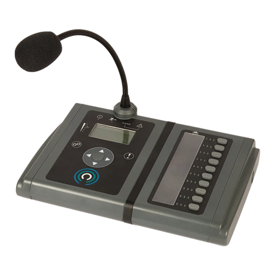
Modular Paging and Emergency Microphones
Installation Guide
ASL Document Ref.: U-0664-0174.doc
Issue: 07 complete, approved - Date: 03/09/14
Part Number: M0664_65
MPS-Series
MPS01-G0
MPS10-G0
MPS10-F0
(OPTIONAL WALL BRACKET)
Advertisement

Related Manuals for ASL INTERCOM MPS Series


Summary of Contents for ASL INTERCOM MPS Series
- Page 1 Sold in Australia by... Morrison's Public Address Phone: 0407442822 Email: sales@morrisonsav.com.au MPS-Series Modular Paging and Emergency Microphones MPS01-G0 MPS10-F0 (OPTIONAL WALL BRACKET) MPS10-G0 Installation Guide ASL Document Ref.: U-0664-0174.doc Issue: 07 complete, approved - Date: 03/09/14 Part Number: M0664_65...
-
Page 2: Table Of Contents
MPS-Series – Installation Guide This equipment is designed and manufactured to conform to the following EC standards: EMC: EN 55103-1/E1-E5, EN 55103-2/E5, EN 50121-4, EN 61000-6-2, EN 61000-6-3, EN 61000-6-4 and EN 55022/B Safety: EN 60065 (pollution degree 2) A “Declaration of Conformity” statement to the above standards is available on request. Voice Alarm: When installed in a Voice Alarm system designed and configured in accordance with the ASL’s EN 54-16 &... -
Page 3: Technical Specification
MPS-Series – Installation Guide Technical Specification Supply Voltage Range ....................15 − 40 V DC or PoE (42 – 57 V DC) Current Consumption (minimum at 24 V DC supply - all LEDs off, LCD display backlight off and sounder off) MPS01................................... - Page 4 MPS-Series – Installation Guide Facilities Message Storage ............. 10 messages of 40 seconds each (minimum) on a micro-SD card Custom Language ........................stored on a micro-SD card Store and Forward....................announcement of up to 60 seconds Format / Colour ..........sloping desk console with optional wall-mounting bracket(s) / grey and black Dimensions (H x W x D) / Weight MPS01...................58 mm x 175 mm x 200 mm (excluding gooseneck) / 1 kg...
-
Page 5: Controls And Indicators
MPS-Series – Installation Guide Controls and Indicators MPS20 (20-BUTTON MICROPHONE) LEDs BUTTON FUNCTION BUTTON (B01 TO B20) Item Description Item Description Function button and indicators. Gooseneck microphone EN 54-16 indication mode • Red LED = Voice Alarm Main user interface (see details below) •... - Page 6 MPS-Series – Installation Guide Main User Interface Item Indicator/Control Description Power On Lit if the unit is receiving DC power. LED (green) Voice Alarm Lit to indicate that a Voice Alarm condition is present in the PA/VA EN54-16 LED (red) system.
-
Page 7: Installation
MPS-Series – Installation Guide Installation Equipment and Tools • The MPS01, MPS10 or MPS20 unit • A pair of wire cutters/strippers • An RJ45 (8P8C) crimping/cable termination tool (only for installation of the wall plate connector) • For wall or desk/console mounting: −... - Page 8 MPS-Series – Installation Guide 3.2.2 Emergency Applications Connection Signals Cable Description Termination Suggested Type From Audio 1 twisted pair, overall screened RJ45 (Mic Port) Suitable CAT5 STP or FTP microphone patch lead Microphone data 1 twisted pair, overall screened to wall socket Power supply 2 twisted pairs, overall screened PTT switch...
- Page 9 MPS-Series – Installation Guide Recommended Installation Procedure Please read and observe the safety information guidelines available on the product and in Section “6 Safety and Precautions” (page 23) prior to installation. Failure to follow these guidelines may cause personal injury and/or damage to the equipment. 3.3.1 Desktop Installation Procedure Connect the installation wiring to the wall socket connector(s) to suit the installation requirements of...
- Page 10 MPS-Series – Installation Guide Ensure that the power supply from the central equipment rack or PoE is turned off. Connect the field cabling from the wall socket to the microphone as required; see Figure 17 (page 18). If used, connect the external audio/music input and/or the speaker/headset audio output, and the contact input and/or output;...
- Page 11 MPS-Series – Installation Guide 3.3.2 Wall and Desk/Console Mounting Installation Procedure To prevent injury, this microphone must be securely attached to the wall/desk in accordance with these installation instructions. Connect the installation wiring to the wall socket connector(s) to suit the installation requirements of the specific location.
- Page 12 MPS-Series – Installation Guide Fit the long and short legs as shown in Figure 8 (page 12) using the previously removed Torx screws. Figure 8 Fitting the long and short legs to the microphone case MPX10 10-BUTTON EXPANSION MODULE: LONG AND SHORT LEGS ON LEFT-HAND SIDE ONLY LONG LEGS SHORT LEGS...
- Page 13 MPS-Series – Installation Guide Route the cables through the cable strain relief guides at the bottom of the microphone and re-fit the cover; see Figure 17 (page 18). Note that a dedicated cable strain relief guide is provided for the audio input/output cables. The contact input/output cables can use the standard cable strain relief guides if required.
- Page 14 MPS-Series – Installation Guide Note that if fixing the microphone to a flat desk or console, it is suggested that the alternative drilling centres shown in Figure 11 (page 14), and that the wall bracket (and R/H bracket if used) be rotated by 180 degrees in order to impart an aesthetically pleasing slant to the mounted unit.
- Page 15 MPS-Series – Installation Guide Offer up the microphone unit to the wall bracket and use two each of the supplied M5 hex screws and washers to fasten the microphone to the wall bracket as shown in Figure 12 (page 15). If used, fasten the microphone to the Right-Hand Side Bracket using one M5 hex screw and washer.
- Page 16 MPS-Series – Installation Guide Fist microphone: fix the fist microphone retaining clip (supplied) to the wall next to the microphone case. Gooseneck microphone: fit the foam windshield to the microphone capsule housing; see Figure 14 (page 16). Figure 14 Fitting the foam windshield Microphone capsule housing Microphone capsule housing with foam windshield fitted...
- Page 17 MPS-Series – Installation Guide 3.3.3 Microphone Settings and Build Standard Figure 16 Removing the bottom cover and configuring the microphone 1) Undo two M4x15 mm screws (Pan Head Pozidriv). The last section of the barcode indicates the Build Standard (BS). Example: 1350 000099 007 BS = 7...
-
Page 18: Connections
MPS-Series – Installation Guide Connections Figure 17 MPS connections (Cover removed) Cable strain relief guide for audio I/O cables (3.5 mm jack) CABLE STRAIN RELIEF GUIDES CABLE TERMINATION OPTIONS SLEEVE RING TRS JACK PLUG SLEEVE RING 2 RING 1 TRRS JACK PLUG U-0664-0174.doc –... - Page 19 MPS-Series – Installation Guide RJ45 Socket Pin No. Signal Description TRANSMIT+ 100BASE-T Ethernet ① TRANSMIT − 100BASE-T Ethernet RECEIVE+ 100BASE-T Ethernet ETHERNET 4 and 5 +V supply input (PoE: 42 – 57 V DC) Ethernet Port RECEIVE − +V supply input (PoE: 42 – 57 V DC) 7 and 8 DC −...
- Page 20 MPS-Series – Installation Guide RJ45 Socket Pin No. Signal CAT5 Cable Description (EIA 568-B) AUDIO+ White/Orange Balanced audio output (+ve / 0 dBu nominal / 220 Ω ) AUDIO − Orange Same as above, but -ve DATA DXP − White/Green RS485 Data+ (19200 baud) +SUPPLY Blue...
- Page 21 MPS-Series – Installation Guide Plug Contact Signal Description LEFT CHANNEL Unbalanced stereo left channel input Ring RIGHT CHANNEL Unbalanced stereo right channel input Sleeve GROUND − Ground ⑦ AUDIO+ Balanced audio input + Ring 1 − − − TRRS Ring 2 AUDIO- Balanced audio input - Sleeve...
-
Page 22: Mechanical Dimensions
MPS-Series – Installation Guide Mechanical Dimensions Figure 18 MPS dimensions ~ 260 mm (maximum) 58 mm 175 mm 165 mm 48.5 mm MPS01 171 mm 35 mm Note: Increase the width by a further 110 mm for each MPX10 Expansion Module. See examples below for MPS10 and MPS20 . -
Page 23: Safety And Precautions
MPS-Series – Installation Guide Unpacking and Handling Safety and The equipment should be unpacked and inspected Precautions immediately on receipt. If damage has occurred please advise your carrier or supplier. Observe all safety information both on the product and in this section. -
Page 24: Application Solutions (Safety And Security) Limited
Service and Warranty Name and Address of Authorised Distributor: This product carries a full warranty. For full details of warranty and service agreements, please contact the Authorised Distributor who supplied the product to you. Exclusions The warranty does NOT cover: Customer misuse, including incorrect installation.
Need help?
Do you have a question about the MPS Series and is the answer not in the manual?
Questions and answers