
Related Manuals for Feig Electronic OBID i-scan ID ISC.MR100-A


Summary of Contents for Feig Electronic OBID i-scan ID ISC.MR100-A
- Page 1 MONTAGE ® OBID i-scan INSTALLATION ID ISC.MR100-A / ID ISC.PR100-A (deutsch / english) final public (B) 2003-08-20 M10202-3de-ID-B.doc...
- Page 2 ® OBID i-scan Montage ID ISC.MR100-A / PR100-A deutsche Version ab Seite 3 english version from page 22 FEIG ELECTRONIC GmbH Seite 2 von 39 M10202-3de-ID-B.doc...
- Page 3 Hinweise jederzeit dankbar. Die in diesem Dokument gemachten Installationsempfehlungen gehen von günstigsten Rahmenbedingun- gen aus. FEIG ELECTRONIC GmbH übernimmt keine Gewähr für die einwandfreie Funktion in systemfrem- den Umgebungen. FEIG ELECTRONIC GmbH übernimmt keine Gewährleistung dafür, dass die in diesem Dokument enthal- tenden Informationen frei von fremden Schutzrechten sind.
-
Page 4: Table Of Contents
6.1. USA (FCC) ........................16 6.2. Europa (CE)........................16 7. Anhang 7.1. Zubehör..........................18 7.1.1. Serielles Datenkabel ID CAB.RS-A ................19 7.1.2. Wandmontagesatz ID ISC.MS.MR/PR-A..............20 7.1.3. RS232/RS485 Umsetzer ID CO.RS232/485 ............. 19 FEIG ELECTRONIC GmbH Seite 4 von 39 M10202-3de-ID-B.doc... -
Page 5: Sicherheits- Und Warnhinweise - Vor Inbetriebnahme Unbedingt Lesen
Alle Arbeiten am Gerät und dessen Aufstellung müssen in Übereinstimmung mit den nationa- len elektrischen Bestimmungen und den örtlichen Vorschriften durchgeführt werden. • Beim Arbeiten an dem Gerät müssen die jeweils gültigen Sicherheitsvorschriften beachtet wer- den. FEIG ELECTRONIC GmbH Seite 5 von 39 M10202-3de-ID-B.doc... -
Page 6: Leistungsmerkmale Der Reader
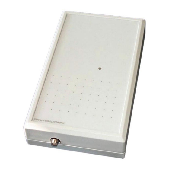
Schnittstelle betrieben werden. Die Adresse des Readers kann dabei per Software vorgegeben werden. 2.2. Verfügbare Readertypen Folgende Reader sind z.Z. verfügbar: Readertyp Beschreibung ID ISC.MR100-A Asynchrone Schnittstelle und externe Antenne ID ISC.PR100-A Asynchrone Schnittstelle und interne Antenne Tabelle 1: Readertypen FEIG ELECTRONIC GmbH Seite 6 von 39 M10202-3de-ID-B.doc... -
Page 7: Montage Und Anschluss
Zum Anschluss der Spannungsversorgung und der asynchronen Schnittstelle befindet sich auf der Leiterplatte ein 9-poliger D-Subminiatur-Steckverbinder (Buchse). Siehe auch Abbildung 1: Leiter- platte mit Jumpern und Anschlusssteckern. Schnittstelle Spannungsversorgung n.c. n.c. n.c. AGND n.c. +12 V DC Tabelle 2: Anschlussbelegung des Steckers X2 FEIG ELECTRONIC GmbH Seite 7 von 39 M10202-3de-ID-B.doc... -
Page 8: Versorgungsspannung
Schaltfrequenz des Netzteils unterhalb von 300 kHz liegt. (Siehe: 7.1.Zubehör) Feig Artikel Nr. Bezeichnung 1688.000.00 ID NET.12VDC Tabelle 5: Empfohlenes Netzteil Hinweis: Das Netzteil wird mit einem DC-Stecker 2,5mm*5,5mm geliefert. Dieser ist passend für das serielle Datenkabel ID CAB.RS-A. FEIG ELECTRONIC GmbH Seite 8 von 39 M10202-3de-ID-B.doc... -
Page 9: Antennenanschluss X4 (Nur Id Isc.mr100)
Betriebserlaubnis des Anwenders erlöschen. Artikel Nr. Bezeichnung 1663.000.00 ID ISC.ANT340/240 Tabelle 7: Antennen mit FCC-Zulassung Hinweis: Die Anschluss-, Inbetriebnahme-, Wartungs-, Messungs- und Einstellungsarbeiten am Gerät dürfen nur von Elektrofachkräften oder Personen mit äquivalenter Ausbildung erfolgen. FEIG ELECTRONIC GmbH Seite 9 von 39 M10202-3de-ID-B.doc... -
Page 10: Asynchrone Schnittstelle
Abbildung 1: Leiterplatte mit Jumpern und Anschlusssteckern Über den Jumper J21 kann die asynchrone Schnittstelle als RS232- oder RS485-Schnittstelle konfiguriert werden. Jumper RS232 RS485 1 - 2 2 - 3 Tabelle 8: Konfiguration RS232/RS485 Schnittstelle FEIG ELECTRONIC GmbH Seite 10 von 39 M10202-3de-ID-B.doc... -
Page 11: Rs232-Schnittstelle
Der Anschluss der RS232-Schnittstelle erfolgt über X2. Die Übertragungsparameter können per Softwareprotokoll konfiguriert werden. Anschlussbelegung X2 (RS232-Schnittstelle): Klemme Kurzzeichen Beschreibung RS232 – TxD RS232 – RxD RS232 – GND Tabelle 10: Anschlussbelegung der RS232 Schnittstelle FEIG ELECTRONIC GmbH Seite 11 von 39 M10202-3de-ID-B.doc... -
Page 12: Rs485 Schnittstelle
Die Adressvergabe erfolgt über den Host-Rechner. Mit Hilfe der Software können dem Reader die Adressen "0" bis "254" zugewiesen werden. Hinweis: Da alle Reader werksseitig die Adresse 0 eingestellt haben, müssen sie nacheinander ange- schlossen und konfiguriert werden. FEIG ELECTRONIC GmbH Seite 12 von 39 M10202-3de-ID-B.doc... -
Page 13: Bedien- Und Anzeigeelemente
Reader-Software. Leuchtet, wenn der Reader betriebsbereit ist. „LABEL“ LED rot Leuchtet, wenn ein Transponder erkannt wird. „INITIALISIERUNG“ LED orange Blinkt während der Reader-Initialisierung nach dem Ein- schalten. Tabelle 12: Standard-Konfiguration der LED FEIG ELECTRONIC GmbH Seite 13 von 39 M10202-3de-ID-B.doc... -
Page 14: Technische Daten
Funktionelle Eigenschaften Unterstützte Transponder • ISO 15693 kompatibel, I•Code 1, Tag-it HF Adresseinstellung für Schnittstelle Software (bis zu 254 Adressen) • Signalgeber optisch • 1 LED ( mehrfarbig – rot / grün) FEIG ELECTRONIC GmbH Seite 14 von 39 M10202-3de-ID-B.doc... - Page 15 - Lagerung -25°C bis +70°C Angewendete Normen • Zulassung Funk - Europa EN 300 330 - USA FCC 47 CFR Part 15 • EN 300 683 Sicherheit • - Europa EN 60950 FEIG ELECTRONIC GmbH Seite 15 von 39 M10202-3de-ID-B.doc...
-
Page 16: Zulassungen
Die Zulassung nach FCC 47 CFR CH. I Part 15 gilt im Zusammenhang mit der Antenne ID ISC.ANT340/240A. 6.2. Europa (CE) Die Funkanlage entspricht, bei bestimmungsgemäßer Verwendung den grundlegenden Anforde- rungen des Artikels 3 und den übrigen einschlägigen Bestimmungen der R&TTE Richtlinie 1999/5/E6 vom März 99. FEIG ELECTRONIC GmbH Seite 16 von 39 M10202-3de-ID-B.doc... - Page 17 ® OBID i-scan Montage ID ISC.MR100-A / PR100-A FEIG ELECTRONIC GmbH Seite 17 von 39 M10202-3de-ID-B.doc...
-
Page 18: Anhang
ID CO.RS232/485 Externer RS232/RS485 Umsetzer 1663.000.00 ID ISC.ANT340/240 Externe Antenne Abm.: 340mm x 240mm x 9mm Schutzart.: IP30 1451.000.00 ID ISC.ANT300/300 Externe Antenne Abm.: 300mm x 300mm x 30mm Schutzart.: IP65 Tabelle 13 FEIG ELECTRONIC GmbH Seite 18 von 39 M10202-3de-ID-B.doc... -
Page 19: Serielles Datenkabel Id Cab.rs-A
Die Spannungsversorgung des Readers darf nicht durch den Umsetzer geführt werden. Dies kann zu der Zerstörung des Umsetzers führen. Gender Changer PC mit RS232 Reader mit Umsetzer Ser. Kabel RS485 incl. Versorgung Abbildung 5: Beispiel Umsetzerschaltung FEIG ELECTRONIC GmbH Seite 19 von 39 M10202-3de-ID-B.doc... -
Page 20: Wandmontagesatz Id Isc.ms.mr/Pr-A
• Die Schrauben auf der Rückseite des Readers entfernen. • Die einzelnen Wandhalter mit denen im Montagesatz beigefügten Schrauben befestigen. Abbildung 6: Montage Wandhalter 65 mm 125 mm Abbildung 7: Montage Bohrmaße FEIG ELECTRONIC GmbH Seite 20 von 39 M10202-3de-ID-B.doc... - Page 21 ® OBID i-scan Montage ID ISC.MR100-A / PR100-A FEIG ELECTRONIC GmbH Seite 21 von 39 M10202-3de-ID-B.doc...
- Page 22 ELECTRONIC GmbH does not give any guarantee promise for perfect function in cross environments. FEIG ELECTRONIC GmbH assumes no responsibility for the use of any information contained in this manual and makes no representation that they free of patent infringement. FEIG ELECTRONIC GmbH does not convey any license under its patent rights nor the rights of others.
- Page 23 12.2. Europe (CE)......................... 35 13. Appendix 13.1. Accessories ........................37 13.1.1. Serial data cable ID CAB.RS-A ................38 13.1.2. Wall mounting kit ID ISC.MS.MR/PR-A ..............39 13.1.3. RS232/RS485 Converter ID CO.RS232/485 ............38 FEIG ELECTRONIC GmbH Page 23 of 39 M10202-3de-ID-B.doc...
- Page 24 Use of the device and its installation must be in accordance with national legal requirements and local electrical codes . • When working on devices the valid safety regulations must be observed. FEIG ELECTRONIC GmbH Page 24 of 39 M10202-3de-ID-B.doc...
-
Page 25: Performance Features Of The Readers
RS485 interface. The address of the Reader is configured via software. 9.2. Available Reader-Types Following Reader-Types are available at present: Reader-Types Description ID ISC.MR100-A asynchronous interface and external antenna ID ISC.PR100-A asynchronous interface and internal antenna Table 1 FEIG ELECTRONIC GmbH Page 25 of 39 M10202-3de-ID-B.doc... -
Page 26: Assembly And Wiring
A 9-pin D-sub female socket is located on the circuit board for connecting the supply voltage and asynchronous interface. See also Fig. 1: Circuit board with jumpers and sockets Interface Supply voltage n.c. n.c. n.c. AGND n.c. +12 V DC Table 2: Pin configuration X2 FEIG ELECTRONIC GmbH Page 26 of 39 M10202-3de-ID-B.doc... -
Page 27: Supply Voltage
Part No. 1688.000.00 ID NET.12VDC Table 5: Recommended power supply Note: The power supply is supplied with a DC plug 2.5mm x 5.5mm. This is compatible with the serial data cable ID CAB.RS-A. FEIG ELECTRONIC GmbH Page 27 of 39 M10202-3de-ID-B.doc... -
Page 28: Antenna Terminal X4 (Only Id Isc.mr100)
ID ISC.ANT340/240 Table 7: Antennas with FCC Approval Note: Electrical connection, commissioning, maintenance, measurement and calibration work on the unit is to be performed only by electrical specialists or persons with equivalent training. FEIG ELECTRONIC GmbH Page 28 of 39 M10202-3de-ID-B.doc... -
Page 29: Asynchronous Interface
Fig. 1: Circuit board with jumpers and sockets Jumper J21 is used to configure the asynchronous interface as RS232 or RS485. Jumper RS232 RS485 1 - 2 2 - 3 Table 8: Configuring as RS232/RS485 FEIG ELECTRONIC GmbH Page 29 of 39 M10202-3de-ID-B.doc... -
Page 30: Rs232 Interface
The transmission parameters can be configured using software protocol. Pin assignments X2 (RS232 interface): Terminal Abbrev. Description RS232 – TxD RS232 – RxD RS232 – GND Table 10: Wiring assignments for the RS232 FEIG ELECTRONIC GmbH Page 30 of 39 M10202-3de-ID-B.doc... -
Page 31: Rs485 Interface
Addresses are assigned by the host computer. Using the software, addresses “0” to “254” can be assigned to the Reader. Note: Since all Readers are factory set with Address 0, you must connect and configure them one after the other. FEIG ELECTRONIC GmbH Page 31 of 39 M10202-3de-ID-B.doc... -
Page 32: Control And Display Elements
Turns on when the Reader is ready. „LABEL“ LED red Turns on when a transponder is detected. „INITIALIZING“ LED orange Flashes during Reader initialization after power-up. Table 12: Standard configuration of the LEDs FEIG ELECTRONIC GmbH Page 32 of 39 M10202-3de-ID-B.doc... -
Page 33: Technical Data
Functional properties Supported transponders • ISO 15693 compatible, I•Code 1, Tag-it HF Address setting for interface Software (up to 254 addresses) • Visual indicators • 1 LED ( multicolor – red / green) FEIG ELECTRONIC GmbH Page 33 of 39 M10202-3de-ID-B.doc... - Page 34 - Storage -25°C to +70°C Applicable Norms • Radio approval - Europe EN 300 330 - USA FCC 47 CFR Part 15 • EN 300 683 Safety • - Europe EN 60950 FEIG ELECTRONIC GmbH Page 34 of 39 M10202-3de-ID-B.doc...
-
Page 35: Approvels
12.2. Europe (CE) When used according to regulation, this radio equipment conforms with the basic requirements of Article 3 and the other relevant provisions of the R&TTE Guideline 1999/E6 dated March 99. FEIG ELECTRONIC GmbH Page 35 of 39 M10202-3de-ID-B.doc... - Page 36 ® OBID i-scan Installation ID ISC.MR100-A / PR100-A FEIG ELECTRONIC GmbH Page 36 of 39 M10202-3de-ID-B.doc...
-
Page 37: Appendix
1663.000.00 ID ISC.ANT340/240 External antenna Dimensions: 340mm x 240mm x 9mm Enclosure rating.: IP30 1451.000.00 ID ISC.ANT300/300 External antenna Dimensions: 300mm x 300mm x 30mm Enclosure rating.: IP65 Table 13: Accessories FEIG ELECTRONIC GmbH Page 37 of 39 M10202-3de-ID-B.doc... -
Page 38: Serial Data Cable Id Cab.rs-A
The supply voltage for the Reader is not permitted to be brought through the converter. This could destroy the converter. Gender Changer PC with RS232 Reader with Serial cable Converter RS485 incl. power supply Fig. 5:Example: converter circuit FEIG ELECTRONIC GmbH Page 38 of 39 M10202-3de-ID-B.doc... -
Page 39: Wall Mounting Kit Id Isc.ms.mr/Pr-A
Remove the screws from the back side of the Reader • Attach the individual wall hangers using the screws supplied with the mounting kit • Fig. 6: Mounting wall hangers 65 mm 125 mm Fig. 7: Mounting drill dimensioning FEIG ELECTRONIC GmbH Page 39 of 39 M10202-3de-ID-B.doc...
Need help?
Do you have a question about the OBID i-scan ID ISC.MR100-A and is the answer not in the manual?
Questions and answers