Table of Contents
Advertisement
Advertisement
Table of Contents

Related Manuals for Microsens MS400863M


Summary of Contents for Microsens MS400863M
- Page 1 Gigabit Ethernet Switch With 10G Uplinks User Manual MS400863M July 2019...
-
Page 2: Table Of Contents
Network Interfaces and Cabling ................. 10 4.3.1 RJ-45 Ports ......................10 4.3.2 SFP/SFP+ Slots ....................... 11 Management Interfaces ....................12 WEB Interface ......................... 12 CLI Interface ........................13 Specification ........................14 Disclaimer ........................15 ©2019_MICROSENS GmbH & Co. KG_Küferstr. 16_59067 Hamm/Germany_www.microsens.com... -
Page 3: About This User Manual
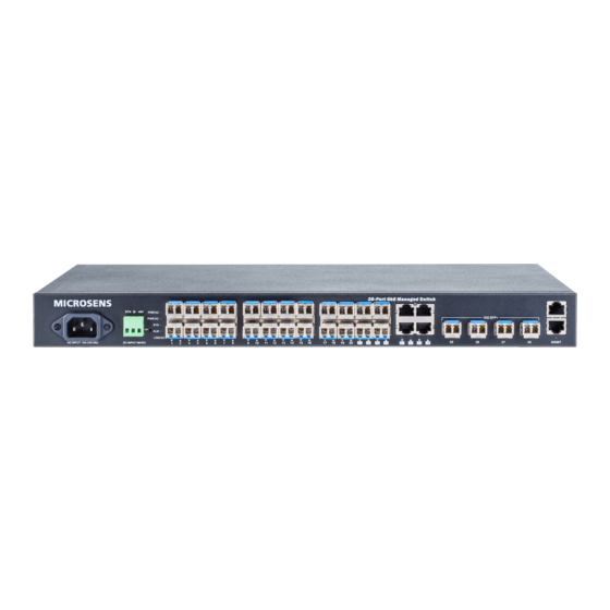
2 Introduction 2.1 Overview The Gigabit Ethernet switch MS400863M provides 20 regular SFP slots, 4x SFP/TP combo ports and 4x 1/10G SFP+ uplink ports. The device performs a wire-speed, non-blocking switching fabric. This allows wire-speed transport of multiple packets at low latency on all ports simultaneously. -
Page 4: Hardware
100~240 VAC power socket for AC power input and 48 VDC power input via terminal block. Figure 2: Power Interface 3.2 Earth Terminal Figure 3 shows the earth screw including PE symbol. Figure 3: Earth Screw ©2019_MICROSENS GmbH & Co. KG_Küferstr. 16_59067 Hamm/Germany_www.microsens.com... -
Page 5: Ports
3.4 SFP/SFP+ Ports MS400863M provides the Small Form Factor Pluggable (SFP) transceiver slots port 1 to port 24. The SFP slots 21-24 are shared with RJ-45 ports (combo interface RJ-45/SFP). In the default configuration, if an SFP transceiver (purchased separately) is installed in a slot and has a valid link on the port, the associated RJ-45 port is disabled. - Page 6 The port has no active network cable connected, or it is not established a link to connected device. Otherwise, the port may have been disabled through the switch user interface. Table 2: Port LEDs ©2019_MICROSENS GmbH & Co. KG_Küferstr. 16_59067 Hamm/Germany_www.microsens.com...
-
Page 7: Management Port
All LEDs are Reset the switch 2 ~ 7 seconds switched off green blinking Restore to defaults 7 ~ 12 seconds All LEDs stay on green Table 3: Reset and Factory Default Reset ©2019_MICROSENS GmbH & Co. KG_Küferstr. 16_59067 Hamm/Germany_www.microsens.com... -
Page 8: Installing The Switch
Step 2: Place the switch on a rack shelf in the rack. Push it in until the oval holes in the brackets align with the mounting holes in the rack posts. Step 3: Attach the brackets to the posts. Insert screws and tighten them. ©2019_MICROSENS GmbH & Co. KG_Küferstr. 16_59067 Hamm/Germany_www.microsens.com... -
Page 9: Desktop Or Shelf Mounting
Step 1: Connect the AC power cord to the AC power receptacle of switch. Step 2: Connect the other end of the AC power cord to the AC power outlet. Step 3: Check the system LED. If it is on, the power connection is correct. ©2019_MICROSENS GmbH & Co. KG_Küferstr. 16_59067 Hamm/Germany_www.microsens.com... -
Page 10: Dc Power Supply
Figure 10 shows a RJ-45 port and the corresponding connector. The RJ-45 ports are supporting auto-crossing. Therefore, the use of crossed or straight cables is possible. The auto-crossing function ensures that transmit lines are correctly connected with receiver lines. ©2019_MICROSENS GmbH & Co. KG_Küferstr. 16_59067 Hamm/Germany_www.microsens.com... -
Page 11: Sfp/Sfp+ Slots
Step 6: Connect one end of the cable to the LC port on the switch and the other end to the LC port on the other device. Since LC connectors are keyed, the cable can be attached in only one orientation. ©2019_MICROSENS GmbH & Co. KG_Küferstr. 16_59067 Hamm/Germany_www.microsens.com... -
Page 12: Management Interfaces
If no DHCP server is available, the IP settings must be configured via the console port, which operates as CLI (Command Line Interface). Per default, all interfaces are using the same login (admin) and password (microsens). WEB Interface The switch provides an http or https based WEB interface. Per default, https is enabled. Http can be enabled in the CLI or WEB interface if needed. -
Page 13: Cli Interface
MS400863M(config-if-vlan)# ip address 192.168.1.2 255.255.255.0 MS400863M(config-if-vlan)# exit Show IP interface MS400863M# show ip interface brief Vlan Address Method Status ---- -------------------- -------- ------ 192.168.1.1/24 Manual DOWN Save configurations MS400863M# copy running-config startup-config ©2019_MICROSENS GmbH & Co. KG_Küferstr. 16_59067 Hamm/Germany_www.microsens.com... -
Page 14: Specification
AC Power Input 100 ~ 240 VAC, 50~60 Hz Power Consumption max. 38 W Environmental Conditions Operating Temperature -20…+60° C Humidity 10…90 % (non-condensing) Mechanic Size 44(H) x 442(W) x 211.2(D) mm Weight 3.1 kg ©2019_MICROSENS GmbH & Co. KG_Küferstr. 16_59067 Hamm/Germany_www.microsens.com... -
Page 15: Disclaimer
All information in this document is provided ‘as is’ and subject to change without notice. MICROSENS GmbH & Co. KG disclaims any liability for the correctness, completeness or quality of the information provided, fitness for a particular purpose or consecutive damage.
Need help?
Do you have a question about the MS400863M and is the answer not in the manual?
Questions and answers