
Related Manuals for Massoth eMOTION XLS-M1


Summary of Contents for Massoth eMOTION XLS-M1
- Page 1 XLS-M1 für LGB/Märklin Spur 1 Schnittstelle for LGB/Märklin Gauge 1 Interface 8205000 Wichtige Information zur Inbetriebnahme Important setup information...
-
Page 2: Table Of Contents
Warnhinweise vor der Inbetriebnahme notes thoroughly before installing and gründlich zu lesen und diese zu beachten. operating your decoder. Massoth is not Für Schäden durch Nichtbeachtung der Hin- responsible for any damage if this manual weise übernimmt Massoth keine Haftung. -
Page 3: Information
Information Information 1.1 Beschreibung (Funktionsumfang) 1.1 Description (Summary) Der eMOTION XLS M1 Soundde- The eMOTION XLS-M1 sound de- coder ist speziell für die Märklin coder has been designed to fit the Spur 1 Schnittstelle optimiert Marklin Gauge 1 DCC interface and und unterstützt den gesamten supports the full range of specifi-... - Page 4 im Analogbetrieb genutzt werden analog operation • Resetfunktionen für alle CV-Werte • Reset function for all CV values • 6-Kanal Soundwiedergabe • 6-channel sound • 2 Watt Verstärkerendstufe • 2 Watts amplifier für 8 Ohm Lautsprecher for 8 ohm loudspeakers • Soundlänge bis zu 200 Sekunden • sound capacity up to 200 secs • 4 Fahrgeräusche und 12 Nebenge- • 4 driving sounds and 12 additional...
-
Page 5: Lieferumfang
1.2 Lieferumfang 1.2 Scope of Supply • eMOTION XLS-M1 Dekoder • eMOTION XLS-M1 Decoder • Lautsprecher • Speaker (abhängig vom Lieferumfang) (depends on scope of supply) • Bedienungsanleitung • Manual 1.3 Warnhinweise 1.3 Warning Notes • Die Spannung der Licht- und • The light and function outputs are... -
Page 6: Einbau Und Anschluss
Einbau und Anschluss Hook-Up 2.1 Einbauhinweise 2.1 Installation Notes Bauen Sie den Decoder sorgfältig Install your decoder in compliance nach diesen Anschlussplänen ein. with the connecting diagrams Der Decoder ist generell gegen in this manual. The decoder is Kurzschlüsse oder Überlastung protected against shorts and gesichert. - Page 7 • Before installing the interface into • Vor dem Einbau des XLS-M1 a locomotive, it is highly recom- Decoders muss ein eventuell vor- mended to remove all electronics. handener Analogadapter entfernt This may apply to lighting boards werden. Weitere Vorkehrungen as well as they may have some sind üblicherweise nicht zu treffen.
-
Page 8: Anschluss
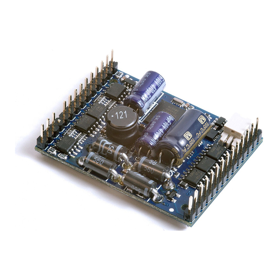
DEC+ A2 (-) DEC+ A3 (-) DEC- Reed2 MOT- A4 (-) Clock/Takt A5 (-) MOT- Reed1 Speaker/LSP1 A6 (-) Speaker/LSP2 DEC+ MOT+ BUS-Clock Speaker/ Lautsprecher Abbildung 1: eMOTION XLS-M1 Decoder Anschlüsse (Oberseite) Illustration #1: eMOTION XLS-M1 contact assignment (top side) - Page 9 2.4 Anschluss auf der Unterseite 2.4 Connectors on the lower surface Auf der Unterseite befinden sich The lower surface offers a number weitere Anschlüsse (Lötkontakte), of connections (soldering con- die zusätzlich genutzt werden kön- tacts) that may be used for addi- nen. (Gute und feine Löterfahrung tional components.
-
Page 10: Inbetriebnahme Und Grundeinstellung
Inbetriebnahme Getting started, Basic Settings und Grundeinstellung This decoder comes with the fol- Dieser Decoder wird ab Werk mit lowing standard factory settings. der folgenden Grundeinstellungen This allows an immediate decoder ausgeliefert. Eine erste Inbetrieb- operation. A detailed configura- nahme ist damit schnell möglich, tion is usually required to set the eine Anpassung jedoch meist decoder to the desired operation... -
Page 11: Programmierung
WICHTIGE HINWEISE ZUR IMPORTANT NOTES FOR PROGRAMMIERUNG PROGRAMMING • Wird der eMOTION XLS-M1 • If the eMOTION XLS-M1 decoder Decoder in Verbindung mit anderen is used in combination with Decodern verwendet, muss die additional decoders, the ad- Programmierung der Adresse vorab dress needs to be programmed erfolgen. -
Page 12: Programmieradresse
jederzeit möglich CV Werte auch decoders are installed the standard im eingebauten Zustand mit an- value CV 16 needs to be changed. If deren Decodern zu ändern. Sollte the programming lock is active and die Programmiersperre aktiv sein you do not remember the value of und Sie wissen den Wert von CV CV 16, you may reset the program- 16 nicht mehr, so können Sie mit... -
Page 13: Einstellungen
Einstellungen Settings Es gibt einige CVs, die besonders Some CVs of special importance wichtig sind und richtig eingestellt require a correct setting for proper sein sollten, damit ein einwandfrei- operation which are explained in the er Betrieb sichergestellt ist. Einige following chapter. - Page 14 5.3 Fahreigenschaften 5.3 Driving Characteristics • Das Fahrverhalten lässt sich über • The driving characteristics can be diverse CVs beeinflussen, z.B.: adjusted with several CVs, e.g.: - Anfahrspannung (CV 2) - Starting voltage (CV 2) - Beschleunigen (CV 3, CV 4) - Acceleration time (CV 3, CV 4) - max.
- Page 15 The bus mode is set in CV 49, Bit Busart definiert. Bit 4 unterschei- 4 and Bit 7. Bit 4 selects between det zwischen Massoth und SUSI Massoth and SUSI mode. Bit 7 Busart. Bit 7 unterscheidet den selects the type of SUSI as SUSI SUSI Bus zwischen Standard-SUSI standard or Märklin Train Bus...
- Page 16 • 133 (Reset CV 200 – 212) • 133 (reset CV 200 – 212) 5.10 Firmwareupdate 5.10 Software update Der eMOTION XLS-M1 Soundde- The eMOTION XLS-M1 Decoder coder kann über das DiMAX PC may be updated with the DiMAX Programmiermodul upgedatet PC module.
-
Page 17: Soundfunktionen (Sound-/Funktions- Zuordnung, Fahrgeräusche, Etc.)
Soundfunktionen Sound Functions Der eMOTION XLS-M1 Sound- The eMOTION Sound Decoder decoder gibt den Funktionsum- contains a full fledged digital fang einer Lokomotive in hoher power amplifier which reproduces Qualität realistisch wieder. Dabei all sounds and side noises of a beschränkt sich der eMOTION locomotive in high quality and very XLS-M1 Decoder nicht rein auf realistically. - Page 18 Geräusche, die jeweils individuell listed in this table. Each eMOTION zugeordnet sind. (siehe Deco- XLS-M1 Decoder carries up to 16 derdatenblatt). Jeder eMOTION sounds and side-noises which are XLS-M1 Soundecoder verfügt über assigned to the F-keys. Besides bis zu 12 Geräusche, die einzelnen the sounds other functions are Funktionstasten zugeordnet sind.
- Page 19 6.2 Fahrgeräusche 6.2 Driving sounds Die Fahrgeräusche der 3 Loktypen, The driving sound vary with the Dampf-, Diesel- und E-Lok sind locomotive type: steam, diesel, or unterschiedlich und gliedern sich electric which are typically ordered üblicherweise in vier Bereiche: in four parts as follows: • Aufrüsten • Start up • Standgeräusche...
- Page 20 onstaste, mit der das Geräusch stands for F-key 1. CV 151 contains geschaltet wird, eingetragen, in the number of loops (repetitions) diesem Fall eine 1, also Funktions- of the sound. The sound will be taste 1. repeated once if the CV contains In CV 151 wird die Anzahl der a “1“, twice if the CV contains a Wiederholungen eingetragen.
- Page 21 6.4 Automatische Geräusche 6.4 Automatic sounds 6.4.1. Starting signal 6.4.1. Anfahrsignal The engineer gives a warning signal Bei dem Anfahren der Lok ertönt with the whistle shortly before the ein Anfahrsignal, z.B. ein kurzes train starts moving. The sound for Pfeifsignal.
- Page 22 6.4.3. Bremsgeräusch (CV 149, Bit 5) 6.4.3. Braking noise (CV 149, Bit 5) Wenn die Lok abbremst wird das This sound is produced automati- Bremsgeräusch automatisch aus- cally when the locomotive slows gelöst (ist bei Auslieferung aktiv). down for stopping (activated fac- Es sind 2 Schwellwerte program- tory preset).
- Page 23 6.4.5. Standgeräusche 6.4.5. Standing noises Die Standgeräusche sind eine The standing noises is a series of Abfolge von maximal 4 Geräu- max. 4 sounds which are produced schen, die einmal nach Halt der Lok after the locomotive has stopped. ausgegeben werden. Diese werden These sounds are activated in mit CV 149 Bit 1 aktiviert.
- Page 24 (CV 201 - CV 212) (CV 201 - CV 212) Der Sounddecoder bietet die The eMOTION XLS-M1 Decoder Möglichkeit die Lautstärke per CV- features volume control by CV- Programmierung einzustellen. So programming. The volume of the kann direkt während des Betriebs...
-
Page 25: Lautsprecher & Lautstärke
• Bei einer Zweikraftlok • Dual Power Locomotive E-Lok-Sound Electric Sound - CV 217 Aufrüsten - CV 217 Start up - CV 218 Standgeräusch - CV 218 Standing noise - CV 219 Abrüsten - CV 219 Shut down - CV 220 Fahrgeräusch - CV 220 Driving sound Dieselsound Diesel Sound... -
Page 26: Drehzahlregelung
Geräusch ertönt, erkennt die sound starts, the eMOTION XLS-M1 Elektronik das Poti und program- Decoder will recognize the external miert die CV 200 um auf 255. Dabei volume control and subsequently führt die Elektronik einen Reset aus. will program CV 200 to 255. There- Jetzt können Sie die Lautstärke mit... - Page 27 viele Magnete notwendig sind um to produce. einen Dampfstoß zu erzeugen. Bei Dampflokomotiven: Steam locomotives: 0 = Steuerung per Fahrstufen 0 = Control by speed steps 1 = ein Dampfstoß je Magnet 1 = one chuff per magnet 2 = ein Dampfstoß je zwei Magnete 2 = one chuff per two magnets 4 = ein Dampfstoß...
-
Page 28: Technische Daten
10. Garantie & Kundendienst 10. Warranty & Customer Service MASSOTH gewährt die Fehler- MASSOTH warrants this product freiheit dieses Produkts für ein against defects in materials and Jahr. Die gesetzlichen Regelungen workmanship for one year from können in einzelnen Ländern... -
Page 29: Contact
Für Schäden durch unsachgemäße directly to the manufacturer. Return Behandlung oder Fremdeingriff shipping charges are not covered oder Veränderung des Produkts by MASSOTH. Please include your besteht kein Garantieanspruch. Der proof of purchase with the returned Anspruch auf Serviceleistungen goods. - Page 30 CV - Tabelle (Fahreinstellungen) Diese Tabelle zeigt die Standardeinstellungen. (S = Standard, A = Analogbetrieb) Konfigurationsvariablen (CV-Tabelle) CV Beschreibung A Bereich Bemerkung Lokadresse (standard kurz) 1... 127 wenn CV 29, Bit 5 = 0 Anfahrspannung (in Fahrstufe 1) 1... 255 CV 2 x (1/255 Gleisspannung) Anfahrverzögerung √...
- Page 31 CV - Table (drive settings) This table shows the standard settings. (D = Default, A = analog operation) Table of configuration variables CV Description Range Note: Loco address (Standard short) 1... 127 If CV 29 bit 5 = 0 Starting voltage 1... 255 CV 2 x (1/255 track voltage) Acceleration time √...
- Page 32 42 MZB-Schaltbefehl f. SUSI Funktion 22 43 MZB-Schaltbefehl f. SUSI Funktion 23 44 MZB-Schaltbefehl f. SUSI Funktion 24 47 Puffernachlaufzeit analog / digital √ 1... 240 (Sek.) nur bei Pufferbetrieb 49 MASSOTH Konfiguration 146 √ bitweise Programmierung Wert AUS (Wert 0) Bit 0...
- Page 33 Digital Load Control OFF Digital Load Control ON Bit 2 Analog Load Control OFF Analog Load Control ON Bit 4 Massoth bus protocol SUSI bus protocol (see Bit 7) Bit 5 Electronic locking brake OFF Electronic locking brake ON Bit 6...
- Page 34 Konfigurationsvariablen (CV-Tabelle) CV Beschreibung A Bereich Bemerkung 50 Licht: Dimmwert (PWM) √ 1... 32 32 = volle Gleisspannung 51 Licht vorne Schaltbefehl siehe Anhang 1 52 Licht hinten Schaltbefehl siehe Anhang 1 53 A1 + A2 Dimmwert √ siehe Anhang 2 54 A1 Schaltbefehl siehe Anhang 1 55 A1 Sonderfunktion...
- Page 35 Table of configuration variables CV Description Range Note: 50 Light: Dimming Value (PWM) √ 1... 32 32 = full track voltage 51 Front Light: Command Allocation see attachment 1 52 Rear Light: Command Allocation see attachment 1 53 A1 + A2 Dimming Value √...
- Page 36 Konfigurationsvariablen (CV-Tabelle) CV Beschreibung A Bereich Bemerkung 116 A4 Sonderfunktion √ siehe Anhang 3 + 3a 117 A5 Schaltbefehl siehe Anhang 1 118 A5 Sonderfunktion √ siehe Anhang 3 119 A6 Schaltbefehl siehe Anhang 1 120 A6 Sonderfunktion √ siehe Anhang 3 + 3A 121 A7: Schaltbefehl 0 ...
- Page 37 Table of configuration variables CV Description Range Note: 116 A4 Special function √ see attachment 3 + 3a 117 A5 Command allocation see attachment 1 118 A5 Special function √ see attachment 3 119 A6 Command allocation see attachment 1 120 A5 Special function √...
- Page 38 Konfigurationsvariablen (CV-Tabelle) CV Beschreibung Bereich Bemerkung 147 Sound An/Aus: Schaltbefehl 0...16 Ab-/Aufrüsten 0...16 Zylindernebengeräusch bei Dampfloks 149 MASSOTH Soundkonfiguration √ bitweise Programmierung Wert AUS (Wert 0) Bit 0 Zufallsgenerator AUS Zufallsgenerator AN Bit 1 Standgeräusch AUs Standgeräusch AN Bit 2 Normales Fahrgeräusch Lastabhängiges Fahrgeräusch Bit 3 Zylinderhähne zu...
- Page 39 Table of configuration variables CV Description Range Note 147 Amplifier On/Off : Switch. command 0...16 Loco start up/shut down, resp. cylin- 0...16 der sound (Steam engine) 149 MASSOTH Sound Configuration √ bitwise programming Wert AUS (Wert 0) Bit 0 Random Generator OFF Random Generator ON Bit 1 Standing Noise OFF...
- Page 40 Konfigurationsvariablen (CV-Tabelle) CV Beschreibung Bereich Bemerkung 0 ... 16 = Funktionstaste für Funktionstaste für Zahnraddampflok 0...16 Zahnstangengeräusch oder oder Zweikraftlok (ab V2.5) Umschaltung E-Lok/Diesellok 171 1. Standgeräusch: Soundzuordnung 0...12 0 = kein Sound 1...12 = Zuordnung der 172 2. Standgeräusch: Soundzuordnung 0...12 Zusatzsounds (Zusatzsounds 173 3.
- Page 41 Table of configuration variables CV Description Range Note 0 ... 16 = F-key for rack rail Function key for steam rack rail loco 0...16 sound or switch-over Electric/ and dual power locos (since V2.5) Diesel locomotive 171 1. Standing noise : Sound assignment 0...12 0= no standing noise 1…12= assignment of 172 2.
- Page 42 Konfigurationsvariablen (CV-Tabelle) CV Beschreibung Bereich Bemerkung 0 = kein externer Taktgeber 195 Taktgeber Steuerregister 0...4 1...4 = Anzahl der Magnetpole für je einen Dampfstoß 0...32 = Länge des Dampf- 196 Dampfstoßdauer 0...32 stoßes 0...16 = Multiplikator der 198 Dampfstoßabstand (Radumdrehung) 0...16 Dampfstoßlänge mit Faktor 3 1...63 1 = leise, 63 = laut...
- Page 43 Table of configuration variables CV Description Range Note 0= no external pulse generator 195 Pulse generator control register 0...4 1…4= number of magnet poles per each steam chuff 0...32 duration of a steam 196 Duration of a steam chuff 0...32 chuff 0...16 pause time between 198 Spacing between steam chuff 0...16 chuffs...
- Page 44 Konfigurationsvariablen (CV-Tabelle) CV Beschreibung Bereich Bemerkung 229 Auslöseschwelle 1 Stufensch. Digital 0...255 230 Auslöseschwelle 2 Stufensch. Digital 0...255 231 Auslöseschwelle 3 Stufensch. Digital 0...255 232 Auslöseschwelle 4 Stufensch. Digital 0...255 233 Auslöseschwelle 5 Stufensch. Digital 0...255 234 Geräusch b. Beschleunigen, Stufensch. 11 0...255 235 Zeit bis Schaltvorgang 0...16 (0,15 sec/Wert) 0 = deaktiviert...
- Page 45 Table of configuration variables CV Description Range Note 229 Trigger threshold 1 contact switch dig. 16 0...255 230 Trigger threshold 2 contact switch dig. 32 0...255 231 Trigger threshold 3 contact switch dig. 48 0...255 232 Trigger threshold 4 contact switch dig. 112 0...255 233 Trigger threshold 5 contact switch dig.
- Page 46 Anhang 3: CV 55, 57, 114, 116 - Sonderfunktion A1, A2, A3, A4 Wert Verwendung Bemerkung 0 = Dauerbetrieb des Ausgangs (Normale Schaltfunktion) Dauerhaftes symmetrisches Blinken 1... 15 Ausgang blinkt symmetrisch (Zeitbasis 0,25 sec pro Wert) Ausgang schaltet sich nach der Kurzzeitfunktion, Monoflop + 64 abgelaufenen Zeit automatisch aus.
- Page 47 Attachment 3: CV 55, 57, 114, 116 - Special functions A1, A2, A3, A4 Value Application Note 0 = Steady „on“ (Standard operation) Flashing symmetrical 1 - 15 symmetric flashing (Time base 0,25 sec/value) output switches off after time Short term function (Monoflop) + 64 (Time base 0,25 sec/value) additional value must be added short „on“, long „off“...
- Page 48 Anhang 8: CV-Werte bei Decoder-Resetfunktion Resetwert 13 112 113 114 121 123 124 125 126 127 129 130 CV 131 – CV 167 Reset Soundfunktionen CV 171 – CV 199 Reset Standphase CV 200 – CV 220 Reset Lautstärkeeinstellungen (+ CV221 - CV 224 bei Zweikraftlok) Anhang 9: Grundwerte der frei programmierbaren Fahrkurve (CV 67 - 94) Wert Wert 76...
- Page 49 Attachment 8: Default settings at resets Reset value 13 112 113 114 121 123 124 125 126 127 129 130 CV 131 - CV 167 Reset sound functions (Values depends on type of sound) CV 171 - CV 199 Reset standing phase (Values depends on type of sound) CV 200 - CV 220 Reset sound volume settings (+ CV 221 - CV 224 two force locomotives) Attachment 9: Basic values of freely programmable driving curve (CV 67 - 94)
- Page 52 Massoth Elektronik GmbH QUALITY Frankensteiner Str. 28 · D-64342 Seeheim · Germany MADE IN FON: +49 (0)6151-35077-0 · FAX: +49 (0)6151-35077-44 GERMANY eMail: info@massoth.de · www.massoth.de RoHS 032377o COMPLIANT 991073 BDA eMOTION XLS-M1 2015.01...
Need help?
Do you have a question about the eMOTION XLS-M1 and is the answer not in the manual?
Questions and answers