Table of Contents
Advertisement
Quick Links
Advertisement
Table of Contents

Subscribe to Our Youtube Channel
Related Manuals for Gooxi SY204-D12R-G2


Summary of Contents for Gooxi SY204-D12R-G2
- Page 1 SY204-D12R-G2 Dual-Socket High-Density Server Barebones User Manual Rev 1.0...
- Page 2 Preface This manual is of the dual-socket high-density server barebones SY204-D12R-G2. It mainly introduces the characteristic parameters, system configuration and installation method of this product. This high-density server of Gooxi supports 4 dual-socket server nodes, the system is based on the integration of 2U 4-node 12-bay chassis and ®...
- Page 3 Moreover, Gooxi does not guarantee the accuracy or reliability of the results obtained by using this user manual or any information obtained through this user manual.
- Page 4 Glossary: Noun Meaning Intel Xeon ® ® Scalable Processors Platinum Certified power supply is“80 PLUS Platinum”standard, that is, the Platinum Efficiency conversion rate of 20% load is above 90%, that of 50% load is more than Power Supply 94%, and that of 100% load is more than 91% M.
- Page 5 Firmware Trusted Platform Module Input/Output Basic Input-Output System BIOS Complementary Metal Oxide Semiconductor CMOS Management Engine Double Data Rate 4 SDRAM DDR4 Dual-Inline-Memory-Modules DIMMs Registered DIMMs RDIMMs LRDIMM Load-Reduced DIMMs Apache Pass MEZZ Mezzanine Connector CONN Keyboard Video Mouse Complex Programmable Logic Device CPLD Error Correcting Code Cubic Feet Per Minute...
-
Page 6: Table Of Contents
Contents Chapter 1 Product Introduction .......................... 6 1.1 System features ..............................6 1.2 Introduction of system component boards ......................9 1.2.1 Motherboard introduction ........................10 1.2.2 Features of MIB ............................ 12 1.2.3 Features of backplane ..........................13 1.3 System view ..............................14 1.3.1 Front view ............................. 14 1.3.2 Rear view ...............................14 1.3.3 Front panel indicator diagram ....................... -
Page 7: Chapter 1 Product Introduction
Chapter 1 Product Introduction 1.1 System features SY204-D12R-G2 barebone is a high-performance and high-density server product, which supports 4 simple-plug high-performance server nodes and 12 hot-swap hard drive modules in a 2U chassis height. Built-in G2DCN-B server motherboard, supports Intel... - Page 8 Memory slots Supports 16 DDR4 DIMM slots, 8 memory modules per CPU Support DDR4-1866/2133/2400/2666 ECC-RDIMM, ECC-LRDIMM, Type of memory support 3DS-LRDIMM, Intel AEP and other memory ® 4GB, 8GB, 16GB, 32GB (RDIMM) Memory size 32GB, 64GB (LRDIMM) 64GB, 128GB (LRDIMM 3DS) Hard disk 2 SATA ports, support software mode RAID 0, 1 interface...
- Page 9 Windows Server 2012 R2(64bit) ® Windows ® Server 2016 (64bit) Redhat Enterprise Linux Server 7.3(64bit) ® Supported Suse Enterprise Linux Server 12.2(64bit) ® operating Centos ® Enterprise Linux Server 7.3(64bit) systems Ubuntu Server 16.04(64bit) ® VMWare ESXi ® Microsoft ® Hyper-V ®...
-
Page 10: Introduction Of System Component Boards
1.2 Introduction of system component boards SY204-D12R-G2 barebone system board mainly includes the motherboard (MB), the backplane (BP), and the Motherboard Interface Board (MIB). The layout of the whole server system is as the following figure 1.1: Figure 1.1... -
Page 11: Motherboard Introduction
1.2.1 Motherboard introduction SY204-D12R-G2 equipped with G2DCN-B dual-socket server motherboard is based on Intel x86 architecture ® design, adopts Intel Purley platform, based on Intel PCH C621 chipset, with Intel latest generation Xeon Scalable ® ® ® ® CPU, the motherboard supports 2 Xeon Scalable CPUs, only CPU1 supports -F series CPU, each CPU has 8 DIMM ®... - Page 12 The function diagram of the motherboard hardware chip is shown in Figure 1.2: Figure 1.2...
-
Page 13: Features Of Mib
1.2.2 Features of MIB The SY204-D12R-G2 barebone system uses the RM2424-MIB-G2, which is an Motherboard Interface Board adapter board between the motherboard and the backplane to transmit SATA signals, PCIE signal, power supply and related control signals, and support hot-swap function. The main features are as follows: ①... -
Page 14: Features Of Backplane
1.2.3 Features of backplane The SY204-D12R-G2 barebone system uses the RM2412-BP-G2 backplane, which supports 12 hot-swap hard disks. The hard disks supported by this backplane are SAS/SATA hard disks, and each node supports 3 hard disks on average. The RM2412-BP-G2 backplane is an adapter board connecting the MIB and the power distribution board. It... -
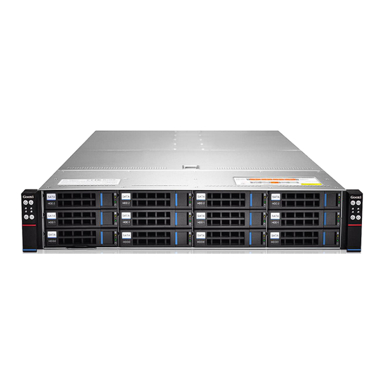
Page 15: System View
1.3 System view 1.3.1 Front view As shown in Figure 1.5 below: Figure 1.5 1.3.2 Rear view As shown in Figure 1.6 below: Figure 1.6... -
Page 16: Front Panel Indicator Diagram
1.3.3 Front panel indicator diagram As shown in Figure 1.7 below: Figure 1.7 The above picture is divided into a clear picture as shown below 1.8 (left),Figure 1.9 (right):_ _ Figure 1.8 Figure 1.9... - Page 17 The above picture shows the functions and LED of the hard drive modules controlled by each node and the modules on the front panel. Each module has its own LED display status, which is described in Table 1.3 below: LED Status Description Picture LED appearance Description...
- Page 18 ¼ Green LED on Node3 network port 2 is connected normally Blue LED Hard disk positioning indication Yellow Hard disk alarm indication LED on Green LED on Hard disk in place indication Table 1.3 1.3.4 Schematic diagram of rear structure Schematic diagram of the location of each node and power supply, as shown in Figure 1.10 below Figure 1.10...
-
Page 19: Chapter 2 System Interface Introduction
Chapter 2 System Interface Introduction 2.1 Overview The main interfaces of the system are distributed on the motherboard. The following content mainly introduces the interface layout of the motherboard. 2.1.1 G2DCN-B motherboard physical picture As shown in Figure 2.1 below: Figure 2.1... - Page 20 2.1.2 Motherboard pin interface definition: The schematic diagram of the motherboard peripheral interface, as shown in Figure 2.2 below: Figure 2.2...
- Page 21 The definition of the motherboard connected to the peripheral interface is as follows in Table 2.1: G2DCN-B Single Board Device Connector Connector S/N Description Remark Customized high-density connector VGA+USB3.0, extension 1 VGA port, 2 USB 3.0 ports Adaptive 1000M, 100M, IPMI LAN Gigabit LAN port (IPMI dedicated) Adaptive 1000M, 100M,...
- Page 22 The schematic diagram of the LED interface of the motherboard, as shown in Figure 2.3: Figure 2.3...
- Page 23 The definition of the motherboard LED interface is as follows in Table 2.2: G2DCN-B Single Board Indicator Connector Connector S/N Description Remark System status LED, located at the rear IO position of the motherboard, using a green + yellow two- color side-emitting indicator for indicating the state of the current node UID LED, located on the back of the IO interface on...
- Page 24 The schematic diagram of the motherboard pin interface is shown in Figure 2.4: Figure 2.4...
- Page 25 The definition of the motherboard pin interface is as follows in Table 2.3: G2DCN-B Single Board Pin Connector Connector S/N Description Remark Built-in hard disk backplane power interface, providing 3.3V, 5V, 12V power supply RS-232 serial-port interface, using 2x5 NC Pin10 pins BMC Debug serial-port interface CPLD Jtag interface for online update of CPLD...
-
Page 26: Motherboard Io Interface
2.2 Motherboard IO interface 2.2.1 System ID LED The system ID indicator is designed to allow users to more intuitively identify which one is currently operating on. Its specific location on the motherboard is as follows. On the front of the motherboard, it corresponds to the ID button on the front panel of the server. -
Page 27: Introduction Of Bmc Led
2.2.2 Introduction of BMC LED The green BMC LED is used to reflect the active status of the motherboard. When the motherboard is powered on, the LED is flashing; when there is no power, the LED is off. The location diagram is as shown in Figure 2.6: Figure 2.6 BMC LEDs are defined as follows in Table 2.4: BMC LED... -
Page 28: Ipmi Lan Port
2.2.3 IPMI LAN port The location diagram is as shown in Figure 2.7: Figure 2.7 IPMI LAN: Also known as Dedicated LAN, it is a dedicated network port for IPMI, which is used for IPMI distance management. It is connected to the switch with CAT5 and above cables, and can also be directly connected to the customer's host. -
Page 29: Lan Port
2.2.4 LAN port The schematic diagram of the location of the network port is as shown in Figure 2.9: Figure 2.9 Note: LAN1 is the NCSI LAN port. NCSI LAN port is also called Shared LAN, which has both IPMI management functions and network port functions. -
Page 30: Vga+Usd Interfaces
2.2.5 VGA+USD interfaces Customized high-density connector VGA+USB3.0, using customized wire, expands 1 standard VGA port and 2 USB3.0 ports. USB3.0 is used to access various USB devices, such as USB keyboard, USB optical drive and U disk or mobile hard disk. The graphics chip of the motherboard adopts AST2500. AST2500 has a built-in PCIE VGA Controller, and uses a customized VGA+USB3.0 adapter to connect to a VGA display and output host information. -
Page 31: Pcie3.0 Interface Introduction
2.2.7 PCIE3.0 interface introduction There are 6 PCIE SLOTs on the motherboard, CPU1 uses all PCIE signals, and CPU2 signals only use Port1. PCIE from CPU1: use 1 x16PCIE expansion card (Port2) in the board slot, 1 i350-AM2 network card (Port3 X4), 1 PCIE X8 MEZZ CONN card (Port3 X8), use 1 set of MIB board expansion PCIE X4 (Port3) and a group of PCIE X16 are used for device expansion on MIB. -
Page 32: Dimm Slot Introduction
2.2.8 DIMM SLOT introduction The motherboard is designed with 16 DIMM SLOTs, which are divided into Channel A1, A2, Channel B1, Channel C1, Channel D1, D2, Channel E1, Channel F1, DIMMA1/DIMMA2 are Channel A DIMM slots; DIMMD1/DIMMD2 are Channel D slots groove. There are two groups of 8 DIMMs per CPU type, CPU1 and CPU2. The DIMM slots are as shown in Figure 2.14: Note: If only 1 DIMM is inserted per Channel, it needs to be inserted in a slot away from the CPU. -
Page 33: Cpu Socket Introduction
2.2.9 CPU SOCKET introduction This motherboard has two LGA3647 CPU sockets for loading the LGA3647 CPU. The schematic diagram of the CPU Socket location is shown in Figure 2.15: Figure 2.15 2.3 Connecting the cable The system structure adopts high-speed signal terminal and adapter board connection, no cable design. 2.4 Jumper setting There are 5* 2PIN pins in the G2DCN-B motherboard, the following table 2.7 is the difference and function introduction of these 2PIN pins:... -
Page 34: Power Module Leds
J23: Use 2PIN jumper cap to insert J23, then it is used to repair ME. 2.5 Power module LEDs Location diagram is as shown in Figure 2.16: Figure 2.16 The arrows in the above figure are the LED of the power module. Each power module has its own LED display status, which is described in Table 2.7 below: LED Status Description Description... -
Page 35: Chapter 3 Detailed Motherboard Disassembly And Assembly
3.1 Extraction of nodes The SY204-D12R-G2 barebone system has 4 hot-swap nodes and easy-to-plug boards. ① Press and hold the node snap button to the left (at the blue circle in the figure below), as shown in the figure 3.1: Figure 3.1... - Page 36 The schematic diagram of the node drawing out the headless device, as shown in Figure 3.3 below: Figure 3.3...
-
Page 37: Disassembly And Assembly Of The Air Duct
3.2 Disassembly and assembly of the air duct After node pulled out, if you want to install or remove the CPU and MIB, the position of the air duct will affect its installation and removal, so you need to remove the air duct first. There is each screw on the side of the node and on the motherboard to fix the air duct. -
Page 38: Disassembly And Assembly Of Mib
3.3 Disassembly and assembly of MIB Before removing the MIB, remove the air duct. For details, please refer to chapter 3.2. Unscrew the fixing screw of the MIB, and then pull it out vertically, as shown in figure 3.6: Figure 3.6 When installing the MIB, align the three MIB expansion slots on the motherboard, insert them vertically downward, and then fix the screws, as shown in Figure 3.7: Figure 3.7... - Page 39 The MIB installation is completed as shown in Figure 3.8: Figure 3.8...
-
Page 40: Installation Of M.2
3.4 Installation of M.2 The SY204-D12R-G2 barebone system has two M.2 ports, the location diagram is as shown in Figure 3.9: Figure 3.9 Note: The location of the memory will affect the installation of M.2, please install the M.2 first, and then install the memory. - Page 41 2-2. Press the other end of the M.2 card to the plane of the positioning stud in step 1, and fix the screw B, as shown Figure 3.11: Figure 3.11 The installation is completed as shown in Figure 3.12: Figure 3.12...
-
Page 42: Installation Of Cpu
® ② Please make sure that the processor parameters you purchase belong to the supported type of this motherboard. ③ If you buy a bulk CPU separately, please make sure your CPU is using a Gooxi certified heat sink. ®... - Page 43 1-2 Press the other end of the clamping piece in the direction of the arrow to fix the CPU to the clamping piece, as shown in Figure 3.14 below. Figure 3.14 Step 2: Install the CPU on the heat sink, and ensure that the surface of the CPU and heat sink is clean and free of oil. 2-1.
- Page 44 Step 3: Installation of CPU heat sink 3-1 Remove the processor blank (protective cover)as shown below 3.16: Figure 3.16 3-2 Align the heat sink with the heat sink fixing studs on the CPU base, and tighten the heat sink fixing screws in sequence according to the instructions, as shown in Figure 3.17: Note: The pins on the motherboard are extremely fragile.
-
Page 45: Disassembly And Installation Of Memory
The motherboard supports 4GB/8GB/16GB/32GB RDIMM, 32GB/64GB LRDIMM, 3DS RDIMM, 3DS LRDIMM DDR4 memory, up to 2666MHz (2666MT/s can only be achieved with a single memory per channel) Notice: R e f e r t o t h e Gooxi official website memory compatibility list for selection. ®... - Page 46 Memory access principle: (1 CPU) Amount of memory (recommended: √ not recommended: O) Memory Processor Memory location √ √ √ √ √ √ channel CPU1 DIMM A1 CPU1 DIMM A2 CPU1 DIMM B1 CPU1 DIMM C1 CPU1 CPU1 DIMM D1 CPU1 DIMM D2 CPU1 DIMM E1 CPU1 DIMM F1...
-
Page 47: Install Memory
3.6.2 Install memory The 8 memory slots controlled by CPU 1 of the motherboard are: DIMMA1, A2, DIMMB1, DIMM C1 and DIMM D1, D2, DIMM E1, DIMM F1; the 8 memory slots controlled by CPU 2 are: DIMMA1, A2, DIMMB1, DIMM C1, a n d DIMM D1, D2, DIMM E1, DIMM F1. - Page 48 NOTICE: When installing or removing DIMM memory modules, extreme care must be taken to prevent any possible damage to the DIMMs or their respective sockets. Installation: Insert the memory module vertically and press down on the memory slot snap position, paying attention to align the bottom of the notch.
-
Page 49: Installation Of Expansion Cards
3.7 Installation of expansion cards This system node supports the expansion of a PCIE X16 expansion card. To install a PCIE expansion card, a Gooxi PCIE adapter card is required. When installing an expansion card, remove the Riser card first. - Page 50 ③ Install the expansion card on the Riser card, as shown in Figure 3.24 below: Figure 3.24 ④ Install the assembled Riser card back into the node, as shown in Figure 3.25 below: Figure 3.25...
- Page 51 The finished picture is as shown in Figure 3.26: Figure 3.26...
-
Page 52: Chapter 4 Barebone System Installation And Maintenance
Chapter 4 Barebone System Installation and Maintenance 4.1 Node installation ① Push the node forward along the chassis track at a constant speed, as shown in Figure 4.1 below: Figure 4.1 ② When it is fully pushed in, you hear a "click", and the node snap (the basket in the picture above) rebounds in place, and the final installation is completed as shown in Figure 4.2: Figure 4.2... -
Page 53: Disassembly And Assembly Of The Upper Cover Of The Chassis
4.2 Disassembly and assembly of the upper cover of the chassis To remove the upper cover, follow the steps below: ① First, unscrew the side screws of the upper cover and lift up the cap A, as shown in Figure 4.3 below: Figure 4.3 ②... - Page 54 When installing the cover, please follow the steps below: ① The upper cover pegs are aligned with the opening of the chassis and placed downwards, as shown in Figure 4.5 below: Figure 4.5 ②Press down the snap cap and lock the screws on both sides of the upper cover of the chassis, as shown in Figure 4.6: Figure 4.6...
-
Page 55: Fan Replacement And Maintenance
4.3 Fan replacement and maintenance The system divides four 8038 fans into two groups, which is convenient for maintenance. Before replacing the fans, you need to take out the upper cover of the chassis. Please refer to chapter 4.2 for the method. Pull out the fan vertically upwards, as shown in Figure 4.7: Figure 4.7 Remove the connector, unplug the fan frame on the left and right sides of the fan, and remove the shock-absorbing plug,... -
Page 56: Front Hard Disk Backplane Installation
4.4 Front hard disk backplane installation ①Align the backplane of the hard disk with the screw holes of the frame, and push it in the direction of the arrow in Figure 4.9 below. Figure 4.9 ②Lock the screws, as shown in Figure 4.10: Figure 4.10... -
Page 57: Installation Of Hard Disk
4.5 Installation of hard disk The whole system supports 12* 3.5-inch hot-swap hard disks. Before installing the hard disks, the hard disk box must be pulled out from the front panel of the whole system. Press and hold the unlocking buckle on the hard disk box (the red circle in the picture below), the wrench on the box will pop out, and then pull out the hard disk box, as shown in the figure below 4.11:... - Page 58 The installation is completed as shown in Figure 4.13: ② Figure 4.13 When the wrench is open, insert the box containing the hard disk into the front hard disk slot of the whole system, and push the hard disk box inward to the end. During the process of closing the wrench, confirm that the hard disk box has entered the chassis again.
-
Page 59: Chapter 5 System Rack Installation
5.2 Steps of system installing into the rack The SY204-D12R-G2 high-performance dual-socket server barebone system adopts a complete set of screw-free tool-free guide rails, which is easy to install. Rails need to use the following steps to install the system into the rack. - Page 60 ③ Figure 5.3 Install the drawn inner rails on the chassis, as shown in Figure 5.4, Figure 5.5, and Figure 5.6. ① Figur Figure 5.4...
- Page 61 ② Figure 5.5 ③ Figur Figure 5.6...
- Page 62 Fasten the rails into the cabinet, and then pull out the middle rails. As shown in Figure 5.7 and Figure 5.8: ① Figure 5.7 ② Figure 5.8...
- Page 63 Raise the entire system, place it on the rails horizontally and push it into the rack. As shown in Figure 5.9 below: Note: The server is heavy and should be lifted by two people to avoid damages. Figure 5.9 Note: During the flat push-in process, there is a buckle in the middle section of the slide rails on both sides, the left buckle is lifted up, and the right buckle is pressed down to continue pushing.
- Page 64 Lock the fixing screws, the whole effect is as shown in Figure 5.11: Figure 5.11 Warning: Do not pull the handles of the server system casually. Otherwise, the system will be pulled out of the rack, which may cause system power failure, downtime, and other failures. The rack must be secure, instability of the rack may cause the rack to tip over.
Need help?
Do you have a question about the SY204-D12R-G2 and is the answer not in the manual?
Questions and answers