Webasto Thermo Top Evo Installation Documentation
Skoda rapid parking heater
Hide thumbs
Also See for Thermo Top Evo:
- Installation documentation (64 pages) ,
- Manual (57 pages) ,
- Workshop manual (52 pages)
Table of Contents
Advertisement
Quick Links
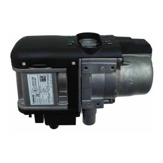
Water Heater
Thermo Top Evo Parking Heater
Installation Documentation
Skoda Rapid
Validity
Manufacturer
Skoda
Motorisation
1.6 TDI CR
1.6 TDI CR Green tec
SG = manual transmission
from Model Year 2013
Left-hand drive vehicle
Verified equipment variants: Manual / automatic air-conditioning system
Not verified:
Total installation time:
Ident. No.: 1319165B_EN
Model
Rapid
Fuel
Transmission type Output in kW
Diesel
SG
Diesel
SG
Front fog light
Headlight washer system
Passenger compartment monitoring
approx. 10 hours
Status: 19.02.2015
E
1
00 0258
Type
EG-BE No./ ABE
NH
e11 * 2007 / 46 * 0250 * ...
77
77
Displacement in cm³ Engine
code
1598
CAYC
1598
CAYC
© Webasto Thermo & Comfort SE
Advertisement
Table of Contents

Related Manuals for Webasto Thermo Top Evo


Summary of Contents for Webasto Thermo Top Evo
-
Page 1: Validity
Water Heater Thermo Top Evo Parking Heater 00 0258 Installation Documentation Skoda Rapid Validity Manufacturer Model Type EG-BE No./ ABE Skoda Rapid e11 * 2007 / 46 * 0250 * ... Motorisation Fuel Transmission type Output in kW Displacement in cm³ Engine code 1.6 TDI CR... -
Page 2: Table Of Contents
Digital Timer Remote Option (Telestart) Preparing Bracket Necessary Components Basic delivery scope Thermo Top Evo in accordance with price list • Installation kit for Skoda Rapid 2013 Diesel: 1319164B • Additionally required in case of automatic air-conditioning: Automatic air-conditioning kit: 1315239C •... -
Page 3: Information On Operating And Installation Instructions
1.7.1. A clearly visible tell-tale in the operator's field of view shall inform when certified in a Webasto training course. NEVER try to install or repair We- the combustion heater is switched on or off. basto heating or cooling systems if you have not completed a Webasto... -
Page 4: Information On Validity
• Crimping pliers for cable lug / tab connector 0.5 - 6mm² • Torque wrench for 2.0 - 10 Nm • Hose clamping pliers • Metric thread-setter kit • Webasto Thermo Test Diagnosis with current software Dimensions • All dimensions are in mm Tightening torque values •... -
Page 5: Preliminary Work
• Remove years that do not apply from the type and duplicate label. • Attach the duplicate label (type label) in the appropriate place in the engine compartment. Heater Installation Location 1 Heater Installation location Ident. No.: 1319165B_EN Status: 19.02.2015 © Webasto Thermo & Comfort SE... -
Page 6: Preparing Electrical System
2 M5x16 bolt, large diameter washer [2x], Installing retaining plate gn/ws rt/sw 0,75² 0,5² 4² 0,5² Connecting wires to pas- senger com- partment relay and fuse holder 4² 4² Ident. No.: 1319165B_EN Status: 19.02.2015 © Webasto Thermo & Comfort SE... - Page 7 The settings must be checked during the start-up of the heater and adjusted if neces- sary. Settings: Checking Duty cycle: 100% IPCU Frequency: not relevant Voltage: 3.6V Function: High-side Ident. No.: 1319165B_EN Status: 19.02.2015 © Webasto Thermo & Comfort SE...
- Page 8 4² 0,5² 0,5² 0,75² Interlocking socket of IPCU and re- 0,5² lay and fuse holder of 0,5² passenger 4² compart- ment and connecting 4² wires 0,5² gn/ws 0,75² Ident. No.: 1319165B_EN Status: 19.02.2015 © Webasto Thermo & Comfort SE...
-
Page 9: Electrical System
Fuse holder of engine compartment Earth wire 1 Retaining plate for fuse holder 1 Earth wire on original vehicle earth support 2 F1-2 fuses mounted point Ident. No.: 1319165B_EN Status: 19.02.2015 © Webasto Thermo & Comfort SE... -
Page 10: Manual Air-Conditioning Fan Controller
20A fuse Fan motor brown Legend 30A fuse Resistor group green 4-pin connector of heater yellow control 1A fuse 25A fuse Cutting point Fan relay Wiring colours may vary. Ident. No.: 1319165B_EN Status: 19.02.2015 © Webasto Thermo & Comfort SE... - Page 11 3 Fuse carrier of passenger compartment Red (rt) wire from K1/87a fan wiring har- ness Black (sw) wire from K1/30 fan wiring Connecting harness passenger compart- ment fuse carrier Ident. No.: 1319165B_EN Status: 19.02.2015 © Webasto Thermo & Comfort SE...
-
Page 12: Automatic Air-Conditioning Fan Controller
1A fuse 25A fuse Fan relay IPCU Pulse width modulator IPCU settings: Duty cycle: 100% Frequency: not relevant Voltage: 3.6 V Cutting point Function: High-side Wiring colours may vary. Ident. No.: 1319165B_EN Status: 19.02.2015 © Webasto Thermo & Comfort SE... - Page 13 2 Connector of A/C control unit 3 Black (sw) wire of connector T16d, Pin14 Red (rt) wire of IPCU/E Black (sw) wire of IPCU/A Connec- tion of A/C control unit Ident. No.: 1319165B_EN Status: 19.02.2015 © Webasto Thermo & Comfort SE...
-
Page 14: Digital Timer
1 M6x20 bolt, flanged nut, existing hole 2 Bracket 3 Receiver Installing receiver 1 Antenna Installing antenna Temperature sensor T100 HTM Fasten temperature sensor 1 with double-sid- ed adhesive tape. Installing tempera- ture sensor Ident. No.: 1319165B_EN Status: 19.02.2015 © Webasto Thermo & Comfort SE... -
Page 15: Preparing Bracket
Insert bracket 2 at position 1 and hori- zontally adjust it upwards as far as possible. 1 Original vehicle stud bolt 3 Copy hole pattern to heat shield plate [4x] Copying hole pat- tern Ident. No.: 1319165B_EN Status: 19.02.2015 © Webasto Thermo & Comfort SE... -
Page 16: Preparing Heater
1 Moulded hose (fuel) 2 10 mm dia. clamp Premount- ing heater Discard section X . Hose B =90°, 18 mm dia. moulded hose Cutting hoses to length Ident. No.: 1319165B_EN Status: 19.02.2015 © Webasto Thermo & Comfort SE... - Page 17 1 Circulating pump 2 Circulating pump mounting 3 M6x25 bolt, large diameter washer, flanged nut 4 Bracket Premount- ing circu- lating pump 1 5x13 self-tapping bolt [3x] Installing bracket Ident. No.: 1319165B_EN Status: 19.02.2015 © Webasto Thermo & Comfort SE...
- Page 18 2 Exhaust end section Preparing exhaust pipe 1 Exhaust pipe 2 Hose clamp [3x] 3 Exhaust silencer 4 Exhaust end section 5 M6x16 bolt, spring lockwasher Installing exhaust system Ident. No.: 1319165B_EN Status: 19.02.2015 © Webasto Thermo & Comfort SE...
-
Page 19: Installing Heater
6 Loosely install M6x30 bolt (will be re- moved again later) 1 M6x20 bolt, spring lockwasher, large di- ameter washer [2x each] Installing heater Ident. No.: 1319165B_EN Status: 19.02.2015 © Webasto Thermo & Comfort SE... -
Page 20: Fuel
2 to the installation location of the metering pump along original vehicle fuel lines. Remove grease from gluing points 1 Adhesive base, cable tie [2 each] Connect- ing heater Ident. No.: 1319165B_EN Status: 19.02.2015 © Webasto Thermo & Comfort SE... - Page 21 1 Original vehicle bolt 2 Perforated bracket Installing metering pump mount 1 Hose section, 10 mm dia. clamp [2x] 2 Metering pump mount 3 Metering pump Installing metering pump Ident. No.: 1319165B_EN Status: 19.02.2015 © Webasto Thermo & Comfort SE...
- Page 22 = 21.6mm 3 Copy hole pattern, 6 mm dia. hole Fuel ex- traction Shape fuel standpipe 1 according to tem- plate, cut to length and install. Installing fuel stand- pipe Ident. No.: 1319165B_EN Status: 19.02.2015 © Webasto Thermo & Comfort SE...
- Page 23 Check the position of the components; adjust if necessary. Check that they have freedom of movement. 1 fuel line, fuel standpipe 2 10 mm dia. clamp [2x] Connect- ing meter- ing pump Ident. No.: 1319165B_EN Status: 19.02.2015 © Webasto Thermo & Comfort SE...
-
Page 24: Combustion Air
Gluing on insulation strip Glue on insulation strips 3 as shown. 1 Original vehicle stud bolt, 51mm dia. p- clamp, plastic nut 2 Silencer 4 Fuel line Installing silencer Ident. No.: 1319165B_EN Status: 19.02.2015 © Webasto Thermo & Comfort SE... -
Page 25: Coolant Circuit
= 25 mm dia. 1 = Original vehicle hose section. 2 = Original vehicle spring clip . 3 = original vehicle quick-release coupling! All connecting pipes without a specific designation = 18x18mm dia. Ident. No.: 1319165B_EN Status: 19.02.2015 © Webasto Thermo & Comfort SE... - Page 26 Install original vehicle hose section 4 as shown on original vehicle quick-release cou- pling 3 . 1 Connection of engine outlet 2 Connection of circulating pump Preparing hoses Ident. No.: 1319165B_EN Status: 19.02.2015 © Webasto Thermo & Comfort SE...
- Page 27 Skoda Rapid 1 Circulating pump Connect- ing heater 1 Black (sw) rubber isolator Routing in engine compart- ment 1 Engine outlet hose section Connect- ing engine outlet Connect- ing heater Ident. No.: 1319165B_EN Status: 19.02.2015 © Webasto Thermo & Comfort SE...
- Page 28 1 Cable tie (temperature resistant) Routing in engine compart- ment 1 Original vehicle quick-release coupling at heat exchanger inlet 2 Original vehicle hose section. Connect- ing heat ex- changer inlet Ident. No.: 1319165B_EN Status: 19.02.2015 © Webasto Thermo & Comfort SE...
-
Page 29: Underbody Trim
2 Discard section Cutting out underbody trim Ensure sufficient distance from neighbouring components. 1 Underbody trim Mounting underbody trim 1 Perforated bracket 2 Discard section Preparing perforated bracket 5x45° Ident. No.: 1319165B_EN Status: 19.02.2015 © Webasto Thermo & Comfort SE... -
Page 30: Guard Plate
3 100 mm edge protection Installing 4 8mm dia. rubber-coated p-clamp guard plate 5 Plastic nut, original vehicle stud bolt 6 M6x30 bolt, spring lockwasher, large di- ameter washer, 10mm shim Ident. No.: 1319165B_EN Status: 19.02.2015 © Webasto Thermo & Comfort SE... -
Page 31: Final Work
• Place caution label "Switch off parking heater before refuelling" in the area of the filler neck • For initial start-up and function test, refer to installation instructions Webasto Thermo & Comfort SE Postfach 1410 82199 Gilching Germany Internet: www.webasto.com Technical Extranet: http://dealers.webasto.com Ident. No.: 1319165B_EN Status: 19.02.2015 © Webasto Thermo & Comfort SE... -
Page 32: Template For Fuel Standpipe
Compare the size of the printed version with dimension lines. Permitted tolerance a maximum of 2%. Set the printer settings to “no margin” or “minimise mar- gins” and 100% of the normal size. 100mm Ident. No.: 1319165B_EN Status: 19.02.2015 © Webasto Thermo & Comfort SE... -
Page 33: Operating Instructions For Manual Air-Conditioning
Skoda Rapid Operating Instructions for Manual Air-Conditioning Please remove page and add to the vehicle operating instructions. Note: We recommend matching the heating time to the driving time. Heating time = driving time Example: For a driving time of approx. 20 min. (in one direction), we recommend not exceeding a switch-on time of 20 min. -
Page 34: Operating Instructions For Automatic Air-Conditioning
Skoda Rapid Operating Instructions for Automatic Air-Conditioning Please remove page and add to the vehicle operating instructions. Note: We recommend matching the heating time to the driving time. Heating time = driving time Example: For a driving time of approx. 20 min. (in one direction), we recommend not exceeding a switch-on time of 20 min.