Optex Smart Line Series Installation Instructions Manual
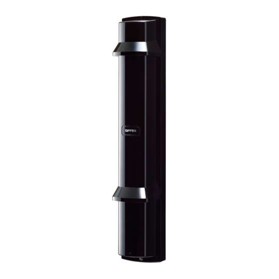
Photoelectric detector
Hide thumbs
Also See for Smart Line Series:
- Installation instructions manual (20 pages) ,
- Installation instructions (4 pages) ,
- Installation instructions (4 pages)
Table of Contents
Advertisement
PHOTOELECTRIC DETECTOR
PHOTOELECTRIC DETECTOR
Smart Line series
Smart Line series
FEATURES
• Quad high power beams
• Smart design
- Slim body design
- Easy-to-see vivid interior color for optical alignment
- IP65 waterproof structure
CONTENTS
1
1-1 BEFORE YOUR OPERATION ....................... 1
1-2 PRECAUTIONS....................................................... 2
1-3 PARTS IDENTIFICATION..................................... 2
2
2-1 SEPARATING................................................. 3
2-2 WIRING .......................................................... 3
2-3 TERMINAL ..................................................... 4
2-4 WIRING DIAGRAM ........................................ 4
SUPPLY AND DETECTOR ............................ 4
2-6 WALL MOUNTING ......................................... 5
2-7 POLE MOUNTING ......................................... 6
1
INTRODUCTION
1-1 BEFORE YOUR OPERATION
• Read this instruction manual carefully prior to installation.
• After reading, store this manual carefully in an easily accessible place for reference.
• This manual uses the following warning indications for correct use of the product, harm to you or other people and damage to your assets, which
are described below. Be sure to understand the description before reading the rest of this manual.
Warning
Caution
This symbol indicates prohibition. The specific prohibited action is provided in and/or around the figure.
This symbol requires an action or gives an instruction.
Warning
Caution
™
™
Failure to follow the instructions provided with this indication and improper handling may cause
death or serious injury.
Failure to follow the instructions provided with this indication and improper handling may cause
injury and/or property damage.
Do not use the product for purposes other than the detection of moving objects such as
people and vehicles. Do not use the product to activate a shutter, etc., which may
cause an accident.
Do not touch the unit base or power terminals of the product with a wet hand (do not
touch when the product is wet with rain, etc.). It may cause electric shock.
Never attempt to disassemble or repair the product. It may cause fire or damage to the
devices.
Do not exceed the voltage or current rating specified for any of the terminals during
installation, doing so may cause fire or damage to the devices.
Do not pour water over the product with a bucket, hose, etc. The water may enter,
which may cause damage to the devices.
Clean and check the product periodically for safe use. If any problem is found, do not
attempt to use the product as it is and have the product repaired by a professional
engineer or electrician.
INSTALLATION INSTRUCTIONS
Model
SL-200QN
SL-350QN
SL-650QN
• View finder with 2X magnification
• Various options (refer to page 12)
( HU-3, ABC-4, BC-4, CBR-4, PSC-4, BAU-4 )
• Beam interruption adjustment function
• Tamper function
2-8 MOUNTING IN THE BEAM TOWER.............. 7
3
3-1 BEAM INTERRUPTION ADJUSTMENT........ 8
4
LOWER BEAM............................................... 8
OPERATION CHECK ........................................... 9
5
6
6-1 HEATER UNIT HU-3 (OPTION) .................... 10
7
DIMENSIONS...................................................... 10
TROUBLESHOOTING ........................................ 11
8
9
SPECIFICATIONS............................................... 11
10
OPTIONS ............................................................ 12
-1-
No. 59-1882-0
Detection range
60m/200ft.
100m/350ft.
200m/650ft.
Advertisement
Table of Contents

Related Manuals for Optex Smart Line Series


Summary of Contents for Optex Smart Line Series
-
Page 1: Table Of Contents
No. 59-1882-0 INSTALLATION INSTRUCTIONS Detection range PHOTOELECTRIC DETECTOR PHOTOELECTRIC DETECTOR Model ™ ™ Smart Line series SL-200QN Smart Line series 60m/200ft. SL-350QN 100m/350ft. SL-650QN 200m/650ft. FEATURES • Quad high power beams • View finder with 2X magnification • Smart design •... -
Page 2: Precautions
1-2 PRECAUTIONS Do not install the unit on an Do not install the pole in a Do not install the unit in a Do not install the receiver in a unstable surface. location where sufficient location where trees, leaves, or location where it is exposed to stability can not be ensured. -
Page 3: Installation
INSTALLATION 2-1 SEPARATING Remove the main unit from the chassis. Remove the cover. Loosen the cover lock screw. A coin (Not included) 2 Twist it lightly. Turn the optical unit 90 degrees Pull the upper part of Pull and loosen the screws (both main unit, and raise it to sides). -
Page 4: Terminal
2-3 TERMINAL <Receiver> <Transmitter> (1) + (1) + POWER INPUT POWER INPUT 10.5-30VDC 10.5-30VDC (2) - (2) - SPARE SPARE (4) N.O. ALARM OUTPUT (5) N.C. (6) COM. SPARE SPARE TAMPER OUTPUT (N.C.) TAMPER OUTPUT (N.C.) 2-4 WIRING DIAGRAM 1 Set Connect the power supplies in parallel. -
Page 5: Wall Mounting
2-6 WALL MOUNTING Open the wiring guide on the back of the chassis using Pull the waterproof packing (x2) marked as "①" at the center of pliers as shown. the chassis. [ Upper ] [ Lower ] Put the waterproof packing back in place. Mount the chassis to the wall. -
Page 6: Pole Mounting
Mount the cover and check the operation. Note>> Hook on the upper part of the chassis. Push the middle part of the cover and hide this orange label completely when in operation. Orange label Push the lower part of the cover until it clicks into position. -
Page 7: Mounting In The Beam Tower
< Installing two detectors in opposing directions > Using a screwdriver or similar tool, break the knockout position Fix the chassis on the pole. (x4) in the chassis as shown. 3×6 self tapping Outside pair of Inside pair of knockouts knockouts marked "③"... -
Page 8: Function Setting
FUNCTION SETTING 3-1 BEAM INTERRUPTION ADJUSTMENT Initial setting is at 50 msec for normal work. According to the speed of a supposed target you select one specific setting out of 4 steps. Set the beam interruption adjustment switches of the Receiver according to the speed of the human object to detect. Dip switch (Receiver) Running... -
Page 9: Operation Check
Note>> Warning Check the diagram below and perform fine alignment Do not look at strong light sources such as for both horizontal alignment and vertical alignment. sunlight through the view finder. Turn the small dial for Caution horizontal alignment. Do not touch the lens during optical alignment. Turn the large dial for vertical alignment. -
Page 10: Optional Setting
OPTION SETTING 6-1 HEATER UNIT HU-3 (OPTION) The heat release effect makes the unit less prone to frost. HU-3 can be mounted to either upper or lower part of the unit. Use a 24 V power supply to use HU-3. <... -
Page 11: Troubleshooting
TROUBLESHOOTING PROBLEM POSSIBLE CAUSE CORRECTIVE ACTION Check the voltage and make sure that it is Inappropriate power voltage between 10.5 and 30 VDC. Indicator LED is not illuminated. See "2-5 WIRING DISTANCE BETWEEN POWER Transmitter : During normal operation SUPPLY AND DETECTOR" on page 4,check the Inappropriate wiring distance or wire diameter Receiver : Light interrupted... -
Page 12: Options
This allows for conduit wiring. Actual length 200 (7.9) Unit: mm (inch) 83 (3.3) 138 (5.4) Unit: mm (inch) OPTEX INCORPORATED (USA) OPTEX SECURITY Sp.z o.o. (POLAND) OPTEX CO., LTD. (JAPAN) TEL:+1-909-993-5770 TEL:+48-22-598-06-55 (ISO 9001 Certified) Tech:(800)966-7839 URL:http://www.optex.com.pl/ (ISO 14001 Certified) URL:http://www.optexamerica.com/...
Need help?
Do you have a question about the Smart Line Series and is the answer not in the manual?
Questions and answers