
Subscribe to Our Youtube Channel
Related Manuals for OPTICOM 764

Summary of Contents for OPTICOM 764
- Page 1 Installation Manual November 2012 Opticom GPS System Intersection Equipment Opticom GPS System Opticom IR System Model 764 Phase Selector...
-
Page 3: Table Of Contents
Intersection Equipment Installation Instructions Table of Contents About This Manual ........................... 5 Intended Use ..........................5 Technical Support ........................5 Safety Messages and Safety Labels ....................5 Safety Considerations ......................... 5 1.4.1 Personal Safety Equipment and Clothing ................5 1.4.2 Work Zone Traffic Control .................... - Page 4 Setup and Testing ........................63 Appendix A: Opticom Output Connection Worksheet (High Priority only) .......... 64 Appendix A1: Opticom Output Connection Worksheet (High & Low Priority) ........65 Appendix B: Driving a Relay from a Phase Selector ................66 Appendix C Gate Opener Card Rack ....................68 Gate Opener Card Rack Installation ....................
-
Page 5: About This Manual
Please read these messages before proceeding with the installation. 1.4 Safety Considerations Please consider the following safety issues before beginning the installation of the Opticom™ System intersection equipment. Although we have compiled this list of common safety considerations, it should not be considered as complete. -
Page 6: Electric Shock
*The method of using the components of the Opticom GPS system may be covered by one or more of US Patent Numbers 5539398, 5926113, 5986575, 6243026. -
Page 7: Description
Intersection Equipment Installation Instructions 2 Description This section provides a general description of the Opticom™ GPS system and a detailed description of the intersection equipment. Opticom GPS System The Opticom GPS system assists authorized priority vehicles through signalized intersections by providing temporary right-of-way through the use of common traffic controller functions. - Page 8 Intersection Equipment Installation Instructions Intersection Equipment Details The Opticom™ GPS System intersection equipment has two styles of Radio/GPS units available. The first is the Model 1010, which is a compact, weather-resistant, Radio/GPS unit containing a GPS receiver with antenna and a 2.4 GHz transceiver with antenna. This model is typically mounted on a traffic pole near the traffic cabinet.
- Page 9 Intersection Equipment Installation Instructions Figure 2-1 Intersection Components...
-
Page 10: Radio/Gps Unit Installation
Intersection Equipment Installation Instructions 3 Radio/GPS unit Installation This section describes the installation of the radio/GPS unit. There are two models of the radio/GPS unit. See section 3.2 for details on installing the Model 1012 Radio/GPS unit. 3.1 Model 1010 Radio/GPS unit mounting Location Considerations Read and understand the following precautionary paragraphs before starting the installation. - Page 11 Intersection Equipment Installation Instructions Figure 3-1. Radio Signal Pattern 1. Cable retainer 3. GPS antenna 2. Intersection radio/GPS unit 4. Radio antenna...
- Page 12 Intersection Equipment Installation Instructions Figures 3-2 through 3-4 show typical installations of the Opticom™ GPS System Intersection Model 1010 Radio/GPS Units. Figure 3-2 shows a Model 1010 radio/GPS unit installed on a mast arm. The radio/GPS unit should be mounted level and higher than the mast arm pole, if possible. Place the unit as far out over the intersection as possible and still provide good coverage down the cross streets.
- Page 13 Intersection Equipment Installation Instructions Figure 3-3 shows a radio/GPS unit installed on a span wire pole. The radio/GPS unit should be mounted level and extended about 3 feet (1m) away from the pole. Figure 3-3. Span Wire Pole Installation Model 1010 Figure 3-4 shows a Model 1010 radio/GPS unit installed on a span wire.
-
Page 14: Model 1010 Radio/Gps Unit Installation
Intersection Equipment Installation Instructions 3.1.1 Model 1010 Radio/GPS Unit Installation NOTE: The mounting location must provide a 3/4-inch NPT internal thread mount. Mounting brackets, nipples, pipe and lock nuts are not included. Choose the mounting location. This is usually the mast arm or span wire pole nearest the traffic controller cabinet. - Page 15 Intersection Equipment Installation Instructions 1. Disassemble the weather-tight cable retainer and route the cable through the compression nut, plastic washer, rubber bushing, and into the cover as shown in Figure 3-6. Leave approximately 4 inches (10 cm) of cable inside the cover and tighten the compression nut to secure the cable. 2.
-
Page 16: Model 1012 Radio Installation
If it is determined by survey of the intersection that these reductions will still allow the Opticom GPS system to operate satisfactorily, then the Model 1012 may be installed. If not, it is recommended that a Model 1010 radio be used. -
Page 17: Model 1050 Antenna Mounting
Intersection Equipment Installation Instructions 3.1.2.1 Model 1050 Antenna mounting NOTES: • Do not paint the radio/GPS antenna cover. Metals or metal oxides in the paint may interfere with GPS reception and/or radio reception and transmission. • Be sure to capture metal shavings when drilling a hole in the cabinet. Antenna mounting factors: •... -
Page 18: Radio Mounting
Intersection Equipment Installation Instructions 3.1.2.2 Radio mounting The Model 1012 radio may be placed on a shelf in the cabinet or it may be mounted using the included self-tapping screws. Figure 3-8. Mounting Model 1012 Radio/GPS Unit 3.1.2.3 Radio/GPS Unit Cable Terminations 1. - Page 19 Intersection Equipment Installation Instructions Figure 3-9. Radio/GPS Cable Connector Pin Configuration Wire Color Function Yellow Radio transmit (+) Yellow Black Radio transmit (–) Blue Radio receive (+) Blue White Radio receive (–) Orange Radio clock (+) Orange Green Radio clock (–) Brown GPS power Brown White...
-
Page 20: Powering The Phase Selector
See figure 5-20 for locations of pins A, B, L, M, N Current Draw: • When powered by 120VAC 60Hz, the Model 764 phase selector current draw is 80 mA o Add 100 mA for the radio/GPS unit o Add 15 mA for each 711 detector... -
Page 21: Phase Selector Installation In Controller Cabinets With Existing Card Racks
Intersection Equipment Installation Instructions 5 Phase Selector Installation in Controller Cabinets with Existing Card Racks CA/NY Type 170 (33X) controller cabinets and some NEMA cabinets have input files that will accept one or two phase selectors. Power input and preemption output wiring is factory installed in the cabinet for the phase selector. - Page 22 Intersection Equipment Installation Instructions Figure 5-1. Phase Selector Installation Using Slot J13 1. Upper input file 3. Phase selector 2. Lower input file Figure 5-2. Input File Continuity Test...
-
Page 23: Potential For Electrical Shock
Intersection Equipment Installation Instructions 5.1 Potential for Electrical Shock A potential exists for a low-current electrical shock (less than 4.5 mA) caused by leakage current in the power supply section of the phase selectors. You may experience this low-current shock when you touch the front of the phase selector, when you insert the phase selector into its slot in the input file, or when you remove the phase selector from its slot. -
Page 24: Phase Selector Installation In Nema Cabinets Using 760 Or 1040 Card Rack
Intersection Equipment Installation Instructions 6 Phase Selector Installation in NEMA Cabinets using 760 or 1040 Card Rack If you will be using the phase selector in GPS only mode a Model 760 or 1040 card rack may be used. If you are using the phase selector in IR or IR/GPS simultaneous mode a Model 760 card rack should be used. - Page 25 Intersection Equipment Installation Instructions 1. Place the card rack at the desired location in the controller cabinet. 2. Install the phase selector into the card rack making sure it is fully seated. See Figure 5-19. 3. Route the 9-pin harness wires to their terminals. 4.
- Page 26 Intersection Equipment Installation Instructions Figure 6-1. 9-Pin Harness Wiring Figure 6-2. Phase Selector Installation...
-
Page 27: Model 1045B Card Rack
Intersection Equipment Installation Instructions 6.1 Model 1045B Card Rack • The Model 1045B card rack may be used in GPS only operation. • The Model 1045B contains a universal power supply that provides 24 VDC to power the phase selector. The 9-pin harness for the model 1045 card rack is identical to the 9-pin harness for the model 760 card rack. -
Page 28: Model 755 Four Channel Adapter Card And Other Model Card Racks
7 Model 755 Four Channel Adapter Card and Other Model Card Racks If you are using your Model 764 phase selector in an existing model 360 or 560 system chassis or a NEMA type card rack that is wired for two, two-channel phase selector, you will need to use a model 755 four- channel adapter card. -
Page 29: Radio/Gps Cable Connection
Intersection Equipment Installation Instructions 8 Radio/GPS Cable Connection 1. Remove the radio/GPS cable to the terminal block on the front of the phase selector. 2. Strip approximately 3 inches (8 cm)) of the outer jacket from the end of the cable. Be careful not to cut the wires inside. -
Page 30: Model 768 Auxiliary Interface Panel (Aip)
Intersection Equipment Installation Instructions Model 768 Auxiliary Interface Panel (AIP) The model 768 auxiliary interface panel (AIP) is an interface device designed to provide for connections between the phase selector and the traffic control cabinet wiring. It provides a breakout of the AIP connector on the front of the phase selector. -
Page 31: Auxiliary Interface Panel Installation
Intersection Equipment Installation Instructions 9.1 Auxiliary Interface Panel Installation Notes: • See tables 9-1, 9-2, and 9-3 for a description of the connectors and terminal strips • Wire gauges from 22 to 16 AWG may be used to connect from the auxiliary interface panel to the traffic control cabinet wiring. - Page 32 Intersection Equipment Installation Instructions Figure 9-2. Model 768 Auxiliary Interface Panel Installation...
-
Page 33: Green Sense Wiring
Intersection Equipment Installation Instructions 9.2 Green Sense Wiring WARNING This procedure may expose you to AC voltage and the risk of electric shock or electrocution. Turn off the AC mains and use accepted and recognized safety precautions to avoid exposure to the risk of electric shock or electrocution. -
Page 34: Confirmation Light Wiring
Each confirmation light is directed toward an approach in the intersection. That approach direction corresponds to one of the channels on the Model 764 phase selector. The installer determines the relationship between approach direction and channel by the detector wiring. - Page 35 Intersection Equipment Installation Instructions Figure 9-3. Confirmation Light Wiring with Load Switch Interface...
-
Page 36: Confirmation Light Wiring With Electromechanical Relay Interface
Intersection Equipment Installation Instructions 9.3.2 Confirmation Light Wiring with Electromechanical Relay Interface This section describes confirmation light using customer supplied relays. The following is recommended specifications for the electromechanical relay: Use a 24 VDC relay with a coil impedance of approximately 1000 ohms. The maximum amount of current that the phase selector output is designed for is 50 mA. - Page 37 Intersection Equipment Installation Instructions 9. Connect a wire to one of the LOGIC COMMON terminals of the auxiliary interface panel. Install a spade lug on the other end of the wire and connect it to the traffic controller logic ground. See Figure 9-4. 10.
-
Page 38: Connecting Existing Harnesses To The Model 768 Auxiliary Interface Panel
In this case it is recommended that the 1030 panel be completely removed and all connections be moved to the 768. If you are using the model 758 for additional functions such as manual control enable, the model 764 phase selector does not currently support this function. It is recommended that a model 752N/754N continue to... -
Page 39: Additional Output Connections
Figure 9-5 Connecting existing Harness/AIP cable 9.5 Additional Output Connections If an Opticom™ System Phase Selector requires more than 4 outputs, it is necessary to make additional connections between the auxiliary interface panel (AIP) and the traffic control cabinet wiring. Outputs for the Time Sync output function are also available on the AIP. - Page 40 Intersection Equipment Installation Instructions Output Terminal Block & Signal Function TB2 OUTPUT 1 Assignable for Preempt, TSP or Time Sync TB2 OUTPUT 2 Assignable for Preempt, TSP or Time Sync TB2 OUTPUT 3 Assignable for Preempt, TSP or Time Sync TB2 OUTPUT 4 Assignable for Preempt, TSP or Time Sync TB2 OUTPUT 5...
- Page 41 Intersection Equipment Installation Instructions Terminal Block & Signal Function TB1 AC IN 1 Phase 1 green sense input Phase 2 green sense input TB1 AC IN 2 TB1 AC IN 3 Phase 3 green sense input TB1 AC IN 4 Phase 4 green sense input TB1 AC IN 5 Phase 5 green sense input...
-
Page 42: Turn Signal Dependant Operation Example
Intersection Equipment Installation Instructions 9.5.1 Turn Signal Dependant Operation Example Figure 9-6 shows an example of an intersection with eight phases numbered 1 through 8. Table 9-4 lists the phase selector outputs to connect to the controller preempt inputs. The table also lists which phases to display. -
Page 43: Infrared (Ir) Operation
A typical use would be for the traffic controller to provide an output which would be used to turn off the outputs from the Opticom system during rail or draw bridge preemption. In this scenario the Opticom system would be prevented from placing emergency vehicle preemption calls or TSP calls while the traffic controller is servicing a rail or draw bridge preemption call. -
Page 44: Phase Selector Pin Index
Intersection Equipment Installation Instructions 11 Phase Selector Pin Index This section is a pin index and diagram of the rear card edge connector. It also contains the pin index of the 11-pin radio/GPS connector and DC Input connector. See section 12 for a pin index of the communication ports. - Page 45 Intersection Equipment Installation Instructions Function DC ground input 24 VDC + input Not used Channel A primary detector input (not used in GPS only mode) Detector 24 VDC power output (not used in GPS only mode) Channel A output, collector (+) Channel A output, emitter (–) Channel B primary detector input (not used in GPS only mode) Detector ground (not used in GPS only mode)
-
Page 46: Communication Ports
Intersection Equipment Installation Instructions 12 Communication Ports Phase selectors have multiple communication ports: • One Ethernet port • One USB port • Four RS-232 ports 12.1 Ethernet Port The default address for the Ethernet port is: IP Address 192.168.0.1 TCP Port 5000 UDP Port 6000... -
Page 47: Usb Port
• The first time you connect your computer to the phase selector using the USB port, your computer will detect a new device called Opticom phase selector. o The drivers will automatically be loaded. o Once complete, a new serial port will be created on your computer. - Page 48 Intersection Equipment Installation Instructions Front Panel COM 1 COM Port Signal Name Pin Number DTR (Data Terminal Ready) TXD (transmit data) RXD (receive data) DCD (Data Carrier Detect) GND (ground) DTR (Data Terminal Ready CTS (Clear to Send) RTS (Ready to Send) RI (ring Indicator) Rear Edge COM 2 COM Port...
-
Page 49: Rs-232 Com Port On The Rear Edge Connector
Intersection Equipment Installation Instructions 12.3.1 RS-232 COM Port on the Rear Edge Connector When shipped from the factory, the rear edge RS-232 communication port is not enabled. To enable the rear edge communication port, remove the two jumpers from their storage positions in positions 2 and 4 on JP4 and place one across pins 1 and 2 and the other across 3 and 4 on JP4. -
Page 50: Rs-232 Com Ports On The Auxiliary Interface Panel
Intersection Equipment Installation Instructions 12.3.2 RS-232 COM Ports on the Auxiliary Interface Panel There are two RS-232 COM ports on the auxiliary interface panel. These ports are labeled COM 3 and COM4. These COM ports are configured for connection to a modem so it is probable that a null modem adapter will be needed when they are used. -
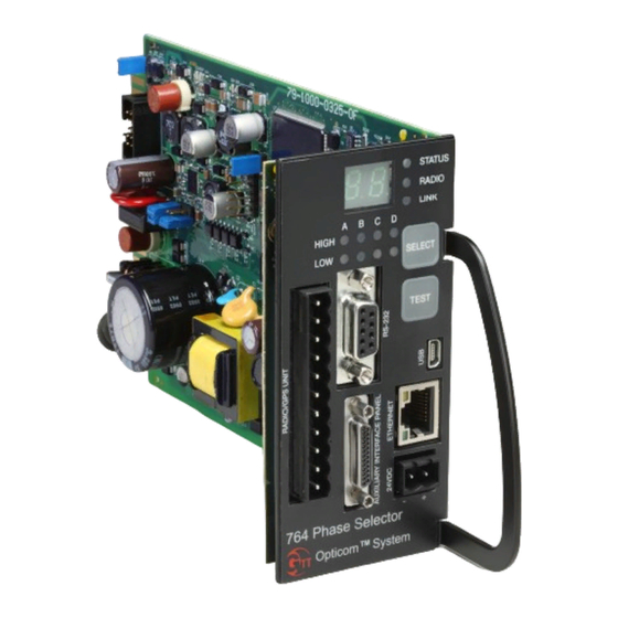
Page 51: Phase Selector Indicators, Display And Switches
13 Phase Selector Indicators, Display and Switches This section describes the indicators and switches on the front panel of the phase selector. 13.1 Indicators The Model 764 phase selector has the following seven indicators. See Figure 13-1 and Table 13-1. • Status •... - Page 52 Intersection Equipment Installation Instructions Table 13-1 lists the LED indicators on the front panel of the phase selector, the color or condition of the LED, and what it means. Indicator Color or Condition Meaning STATUS Phase selector powered off or offline Steady Green Phase selector powered and online Flashing Green...
-
Page 53: Display And Switches
Intersection Equipment Installation Instructions 13.2 Display and Switches Opticom Phase Selectors have a two digit display and two switches. • Select Switch • Test Initiate Switch The Select switch is designed to act in conjunction with the Test switch to provide different operations and tests. -
Page 54: Manual Test Calls
Intersection Equipment Installation Instructions 13.2.1 Manual Test Calls These settings will place manual test calls. If the phase selector outputs are connected to the controller’s preemption/TSP inputs, a live call will be placed to the controller. It is recommended that the controller’s preemption and TSP routines be programmed prior to placing manual test calls. - Page 55 Intersection Equipment Installation Instructions Test Test Call Test Select Test Call Test Select Test Call Test Select Figure 13-2 Direction Submenu...
-
Page 56: Error Listing
Intersection Equipment Installation Instructions 13.2.2 Error listing Er displays a list of active errors, if any exist. • Press the SELECT button to display Er. • Press the TEST button to display any active errors in the system. • Press the SELECT button to display the next error code. •... -
Page 57: Detector Function Test
Intersection Equipment Installation Instructions 13.2.4 Detector Function Test dt Verifies that an infrared detector is connected to each channel. • Press the SELECT button until dt is displayed. • Press the TEST button for one second. o The HIGH LED will illuminate for each channel that has a detector(s), connected. o The indicator will flash for five seconds. -
Page 58: Checkout
Intersection Equipment Installation Instructions 14 Checkout For details on how to check out and test the Opticom™ GPS System, refer to the On-site software Help files. NOTE: When operating in GPS mode or GPS/IR mode the GPS Intersection equipment will not operate until setup and mapping procedures are completed. -
Page 59: Troubleshooting Tables
Intersection Equipment Installation Instructions 15.2 Troubleshooting Tables Table 15-1 shows the symptoms of intersection equipment installation and setup problems. The table also shows the possible causes of the problems and suggests solutions to correct them. Table 15-2 shows the expected voltages at various wiring terminals Table 15-1 Troubleshooting Symptoms, Possible Causes, and Solutions Symptom Possible Cause... - Page 60 Intersection Equipment Installation Instructions Table 15-1 Troubleshooting Symptoms, Possible Causes, and Solutions (continued) Symptom Possible Cause Solution Call LED lights and controller Phase selector timing. Verify that there is no call delay in responds, but green light not phase selector and controller. granted in time.
- Page 61 Intersection Equipment Installation Instructions Table 15-1 Troubleshooting Symptoms, Possible Causes, and Solutions (continued) Symptom Possible Cause Solution RADIO LED is off Incorrect wiring. Check wiring at both ends of radio/GPS cable. Radio/GPS cable connector Plug in terminal block correctly. (terminal block) plugged in backwards.
- Page 62 Intersection Equipment Installation Instructions Table 15-1 Troubleshooting Symptoms, Possible Causes, and Solutions (continued) Intersection alternates displaying Vehicle brake light bulb shared Reconnect vehicle turn signal and dropping the left turn arrow with turn signal indication. sense lines to front turn signal when approaching vehicle has left wires.
-
Page 63: Maintenance
Intersection Equipment Installation Instructions 16 Maintenance Opticom™ GPS System components are designed for reliable operation. Inspect the components at regular intervals to ensure proper system operation. GTT recommends the following: • All components should be inspected at least every twelve months. -
Page 64: Appendix A: Opticom Output Connection Worksheet (High Priority Only)
Intersection Equipment Installation Instructions Appendix A: Opticom Output Connection Worksheet (High Priority only) Intersection Name: _______________________________________ Radio Channel: __________________________________________ Connect Phase Selector Output To Controller Preempt Input Then, Program Controller to Display Greens for: Output _________________________ Input 1 Phases ____ and ____... -
Page 65: Appendix A1: Opticom Output Connection Worksheet (High & Low Priority)
Intersection Equipment Installation Instructions Appendix A1: Opticom Output Connection Worksheet (High & Low Priority) Intersection Name: __________________________ Low Priority Active State ______________________ Radio Channel: _____________________________ Low Priority Output __________________________ HIGH Priority To Controller Preempt Input Then, Program Controller to Display Greens for:... -
Page 66: Appendix B: Driving A Relay From A Phase Selector
It is possible to drive an electro-mechanical or solid-state relay from a phase selector output. However, this application falls outside of the intended use of the Opticom™ GPS System and the system was not designed for this application. Should you do so on your own, it is important to use a relay that falls within the parameters described below to prevent damage to the phase selector. - Page 67 Intersection Equipment Installation Instructions Recommendations • Use a 1N4004 or equivalent diode. • Use a 24 VDC relay with a coil impedance of approximately 1000 ohms. The maximum amount of current that the phase selector output is designed for is 50 mA. The following relay manufactured by IDEC meets the above listed requirements: •...
-
Page 68: Appendix C Gate Opener Card Rack
Opticom GPS vehicle equipment to activate a flasher, sign, etc. The Gate Opener card racks are used in conjunction with an Opticom phase selector and an Opticom GPS radio/GPS unit and or Opticom IR detectors to accomplish these tasks. -
Page 69: Gate Opener Card Rack Installation
Intersection Equipment Installation Instructions Gate Opener Card Rack Installation The card slot in the Model 770 and 1045 Card Rack is dedicated to a phase selector. The edge connector is wired to the connector on the card rack front panel and the terminal strip which is also on the card rack front panel. - Page 70 Intersection Equipment Installation Instructions Connect the harness plug to the round connector on the card rack front panel. Connect the Model 1012 or Model 1010 Radio GPS unit to the phase selector. See section 3 for details. If you are using IR detectors, connect the detectors to the card rack per figure 20-2. See the 711/721/722 detector installation instructions for details on connecting the wires inside of the detector.
-
Page 71: Gate Opener Relay Outputs
Intersection Equipment Installation Instructions Gate Opener Relay Outputs See above for the ratings of the relay contacts. 1. Connect a wire of sufficient gauge to handle the current draw of your gate opener between the Relay Common terminals on the card rack to the appropriate terminal on your gate opener control. 2. - Page 73 Since the availability of a GPS signal is out of GTT’s control and is required for Opticom GPS system...
Need help?
Do you have a question about the 764 and is the answer not in the manual?
Questions and answers