Table of Contents
Advertisement
Quick Links
Advertisement
Table of Contents

Related Manuals for OPTICOM CC03-IP2MVFIR

Summary of Contents for OPTICOM CC03-IP2MVFIR
- Page 1 Installation Manual CC03-IP2MVFIR Camera CC03-IP2MVFIR Installation Manual Opticom Technologies Inc. USA Sales: Battle Creek, Michigan: 800-578-1853 www.opticomtech.com Canada: Head Office (Vancouver): 855-569-3240 www.toughestvideocamera.com March 2016...
-
Page 2: Important Safety Instructions
TO REDUCE THE RISK OF IGNITION DO NOT OPEN WHEN AN EXPLOSIVE GAS ATMOSPHERE MAY BE PRESENT. DISCLAIMER: Opticom Technologies Inc. will not be responsible for injuries or damages resulting from the improper installation or use of any product sold by Opticom Technologies Inc. their agents, distributors or dealers. Opticom Technologies Inc. -
Page 3: Camera Description
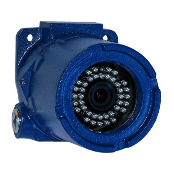
Installation Manual CC03-IP2MVFIR Camera CAMERA DESCRIPTION • 2.43 Megapixel CMOS Image Sensor • 3.5~16mm Varifocal Auto-Iris Lens • 10/100-Base-T Ethernet (auto-sensing) Interface • Maximum Frame Rate of 30FPS @ 2MP (1920x1080) • Dual Streaming (H.264, MJPEG codecs) • 39 Piece Infrared Array - 20m Range •... -
Page 4: Housing Dimensions
Installation Manual CC03-IP2MVFIR Camera HOUSING DIMENSIONS 5/16” Mounting Lugs Opticom Technologies Inc. USA Sales: Battle Creek, Michigan: 800-578-1853 www.opticomtech.com Canada: Head Office (Vancouver): 855-569-3240 www.toughestvideocamera.com March 2016... -
Page 5: Installation
Installation Manual CC03-IP2MVFIR Camera INSTALLATION Install with the appropriate hardware to suit the mounting surface. Select a suitable location that is protected from accidental damage or tampering, and environmental conditions that could exceed the camera’s general specifications. Ensure the selected location is protected from falling objects, accidental contact with moving objects, and unintentional interference from personnel. -
Page 6: Set Screw
Installation Manual CC03-IP2MVFIR Camera ELECTRICAL During installation, it is important to attach a 10 AWG copper stranded wire (minimum requirement) from the earth ground attachment point on the unit to an appropriate grounding location for your installation. The camera can be powered either by PoE (802.3af) (power over ethernet)or by 12VDC using LVT connected the 2.1mm power jack. - Page 7 Installation Manual CC03-IP2MVFIR Camera LENS FOCUSING Removing the housing cover allows access to the varifocal lens adjustment screws. The CC03- IP2MVFIR camera module is equipped with a 3.5~16mm varifocal lens allowing for a viewing angle of between 68 º and 17 º respectively. There are two adjusting screws below the infrared assembly.
-
Page 8: Specifications
Installation Manual CC03-IP2MVFIR Camera Specifications CC03-IP2MVFIR H.264/MJPEG(simultaneous dual stream) Video Encoding H.264/H.264 (true H.264 dual streaming) Simultaneous streaming with independent control Resolution 1920x1080, 1280x720,640x352, 320x176, 160x96 Serial Interface Console, By-pass command to control UART device Bandwidth Management Frame rate control / Bandwidth control / CBR / VBR 10/100-Base-T Ethernet (auto-sensing), 1 DI/DO(3.3V TTL),...
Need help?
Do you have a question about the CC03-IP2MVFIR and is the answer not in the manual?
Questions and answers