
Subscribe to Our Youtube Channel
Related Manuals for Unitron Z12


Summary of Contents for Unitron Z12
- Page 1 STEREO MICROSCOPE MANUAL 73 Mall Drive, Commack, NY 11725 • 631-543-2000 (P) • 631-589-6975 (F) www.unitronusa.com • info@unitronusa.com...
-
Page 3: Table Of Contents
Z12 ZOOM STEREO MICROSCOPE CONTENTS SAFETY NOTES ........................3 CARE AND MAINTENANCE ....................3 INTRODUCTION ........................4 UNPACKING AND COMPONENTS ..................4 COMPONENT DIAGRAMS ....................5 ASSEMBLY DIAGRAM ......................6 DETAILED ASSEMBLY ..................... 7-9 OPERATION ILLUMINATION ........................10 REFLECTOR..........................10 FOCUSING TENSION ...................... -
Page 4: Safety Notes
An annual schedule of preventative ® maintenance by qualified personnel is highly recommended. Your authorized UNITRON distributor can arrange for this service. -
Page 5: Introduction
Z12 ZOOM STEREO MICROSCOPE INTRODUCTION ® ® Congratulations on the purchase of your new UNITRON microscope. UNITRON microscopes are engineered and manufactured to the highest quality standards. Your microscope will last a lifetime if used ® and maintained properly. UNITRON microscopes are carefully assembled, inspected and tested by our staff of trained technicians in our New York facility. -
Page 6: Component Diagrams
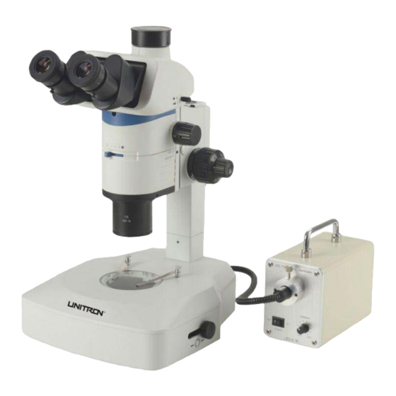
Z12 ZOOM STEREO MICROSCOPE COMPONENTS DIAGRAM Camera/Photo Trinocular Port Viewing Head Light Path Selection Slider Zoom Knob Focus Drive Eyepiece Aperture Coarse/Fine Focus Diaphragm Adjustment Knobs Control Microscope Lock Knob Body Tension Adjustment Collar Objective Stage Insert Plate Base Stage Clip... -
Page 7: Assembly Diagram
Z12 ZOOM STEREO MICROSCOPE ASSEMBLY DIAGRAM The diagram below shows how to assemble the various components. The numbers indicate the order of assembly. Use the 1.5mm and 3mm hex wrenches that are supplied with your microscope when required. Be sure to keep this wrench for changing out components or making adjustments. -
Page 8: Detailed Assembly
Z12 ZOOM STEREO MICROSCOPE DETAILED ASSEMBLY Mount the Focus Drive (Fig. 1-2) Loosen the lock knob ① of the focus drive ②. Position the ② focus drive as shown and gently slide it all the way down onto the column pole ③ until the bottom of the focus drive is flush with the column base ④, Fig. - Page 9 Z12 ZOOM STEREO MICROSCOPE DETAILED ASSEMBLY - continued Mount the Viewing Head (Fig. 5-6) Loosen the lock screw ① on the front of the microscope ④ body with the 3mm mm hex wrench. ⑤ With the eyepiece tubes ② facing forward (as shown in ⑥...
- Page 10 Always use the power cord that is provided with your microscope; using a different power cord may damage your microscope. Should you need a replacement, contact your authorized UNITRON dealer or call UNITRON at 1-631-543- 2000 for a dealer nearest you. ⑧...
-
Page 11: Operation
Z12 ZOOM STEREO MICROSCOPE OPERATION Adjusting the Illumination (Fig. 11) Turn the power switch ① to “ON”. ② ① NOTE: For longer lamp life always turn the light intensity control knob ② to the lowest illumination intensity setting possible before turning the power on or off. -
Page 12: Diopter & Focusing
Z12 ZOOM STEREO MICROSCOPE OPERATION (continued) Adjusting the Diopter & Focus (Fig. 14) Left Diopter Right Diopter Adjustment Ring Adjustment Ring Set the dioptor rings of both eyepieces to “0” position. (Do this when users change, because different users will have different diopter settings.) Place an easy-to-observe specimen on the stage plate, i.e., a coin. -
Page 13: Click/Click Stop
Z12 ZOOM STEREO MICROSCOPE OPERATION (continued) Changing the Click/Click Stop Feature (Fig. 17) ① The microscope is equipped with a Click/Click Stop feature that enables the user to set the magnification value indicated on the zoom knob to stop at each fixed... -
Page 14: Aperture Diaphragm
Selecting the Light Path (Fig. 20) The Z12 is outfitted with a binocular viewing head with ① one photo port for HDMI/digital imaging. You must select the appropriate light path for observing specimens. -
Page 15: Polarizer/Analyzer
Z12 ZOOM STEREO ICAL MICROSCOPE OPERATION (continued) ⑤ Using the Polarizer/Analyzer (Fig. 22) ⑥ ③ The simple polarizer includes the polarizer and ④ ② analyzer. ① Remove the stage insert plate ① (see Fig. 8, p. 3). Insert the polarizer ② with the flat edge closest to... - Page 16 Z12 ZOOM STEREO MICROSCOPE TROUBLESHOOTING Under certain conditions, performance of this unit may be adversely affected by factors other than defects. If a problem occurs, please review the following list and take remedial action as needed. If you cannot solve the problem after checking the entire list, please contact your local dealer for assistance.
-
Page 17: Troubleshooting
Z12 ZOOM STEREO MICROSCOPE TROUBLESHOOTING (continued) MECHANICAL PART PROBLEM CAUSE SOLUTION The coarse adjustment knob is The tension adjustment ring is tightened too Loosen it too difficult to rotate much The image goes out of focus during observation or the stage... -
Page 18: Maintenance
United States of America. All items returned for warranty repair must be sent freight prepaid and insured to Unitron Ltd., 73 Mall Drive, Commack, NY 11725 – USA. All warranty repairs will be returned freight prepaid to any destination within the continental United States of America. For all foreign warranty repairs, return freight charges are the responsibility of the individual/company who returned the merchandise for repair.
Need help?
Do you have a question about the Z12 and is the answer not in the manual?
Questions and answers